Pcb Stencil Project
Introduction
The Inspiration of this project comes from the Fab Xiao project made by Adrian Torres. The Fab Xiao is custom microcontroller that has an equivalent proccessing power to a Rasberry-Pi but in a small form factor.
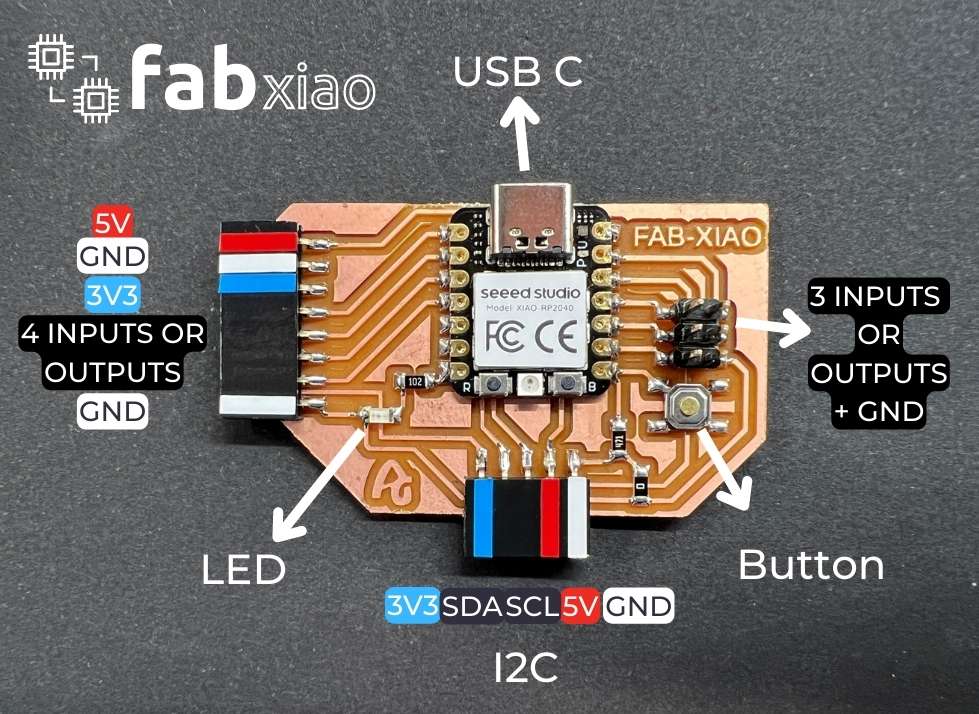
The Fab Xiao’s pcb (Printed circuit board) has many small solder pads that it makes soldering them with a soldering iron a very tedious process. To make this process easier we will be using solder paste and a stencil to quicky cover all the solder pads, then use a heat gun to solder all the parts in place.
This project aims to show the process of creating a stencil for the pcb in aims to make the process of applying soldering paste easier.
Materials / Tools
- Vinyl Cutter (Silhouette Cameo 3)
List of materials from Fab Xiao project
| Materials | Where to buy? | Amount | Price | Total price |
| Proto Board FR1 | Digikey | 1/4 board | 1,24 €/unit | 0,31 € |
| Seeed Studio XIAO RP2040 | Seeed Studio | 1 | 5,00 €/unit | 5,00 € |
| 0Ω resistor | Digikey | 1 | 0,09 €/unit | 0,09 € |
| 499 Ω resistor | Digikey | 1 | 0,09 €/unit | 0,09 € |
| 1kΩ resistor | Digikey | 1 | 0,09 €/unit | 0,09 € |
| LED | Digikey | 1 | 0,35 €/unit | 0,35 € |
| Button | Digikey | 1 | 1,00 €/unit | 1,00 € |
| Female 1 row horizontal header | Digikey | 3 | 0,15 €/unit | 0,45 € |
| Male 2 row vertical header | Digikey | 1 | 0,65 €/unit | 0,65 € |
| Total cost | 8,03 € |
Files
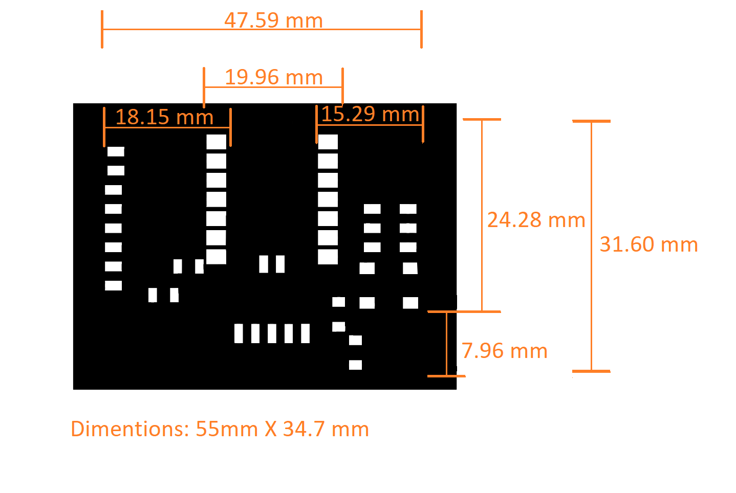
Pcb Dimentions
To get the most accurate results, the dimentions of the pcb as well as the distances between solder pads were accurately measured using a digital ruler.
Vinyl Cutting
Material Settings
We tried several different materials for the stencil and most of them did not produce great results. For instance, we tried using hard paper but we realized quickly that it wasnt going to be durable enough as it would tear apart near the holes of the stencil.
We finally settled on pvc plastic (.1mm thick) as it is both durable and flexible. In addition to that, we can make the stencil thicker by gluing together multiple layers of plastic.
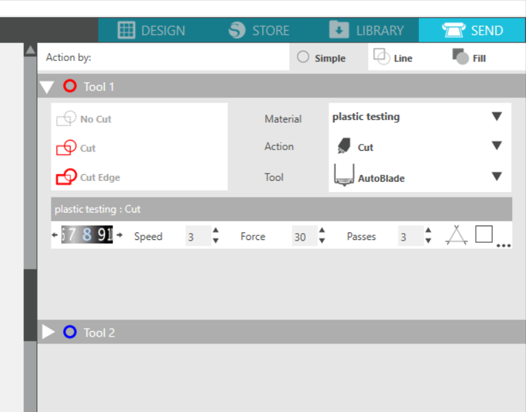
On the other hand, plastic came with it’s own set of challenges as it was tough to cutt using the vinyl cutter. Through trial and error we have managed to find the perfect settings to cutt plastic on our vinyl cutter (Sillouette Cameo 3).
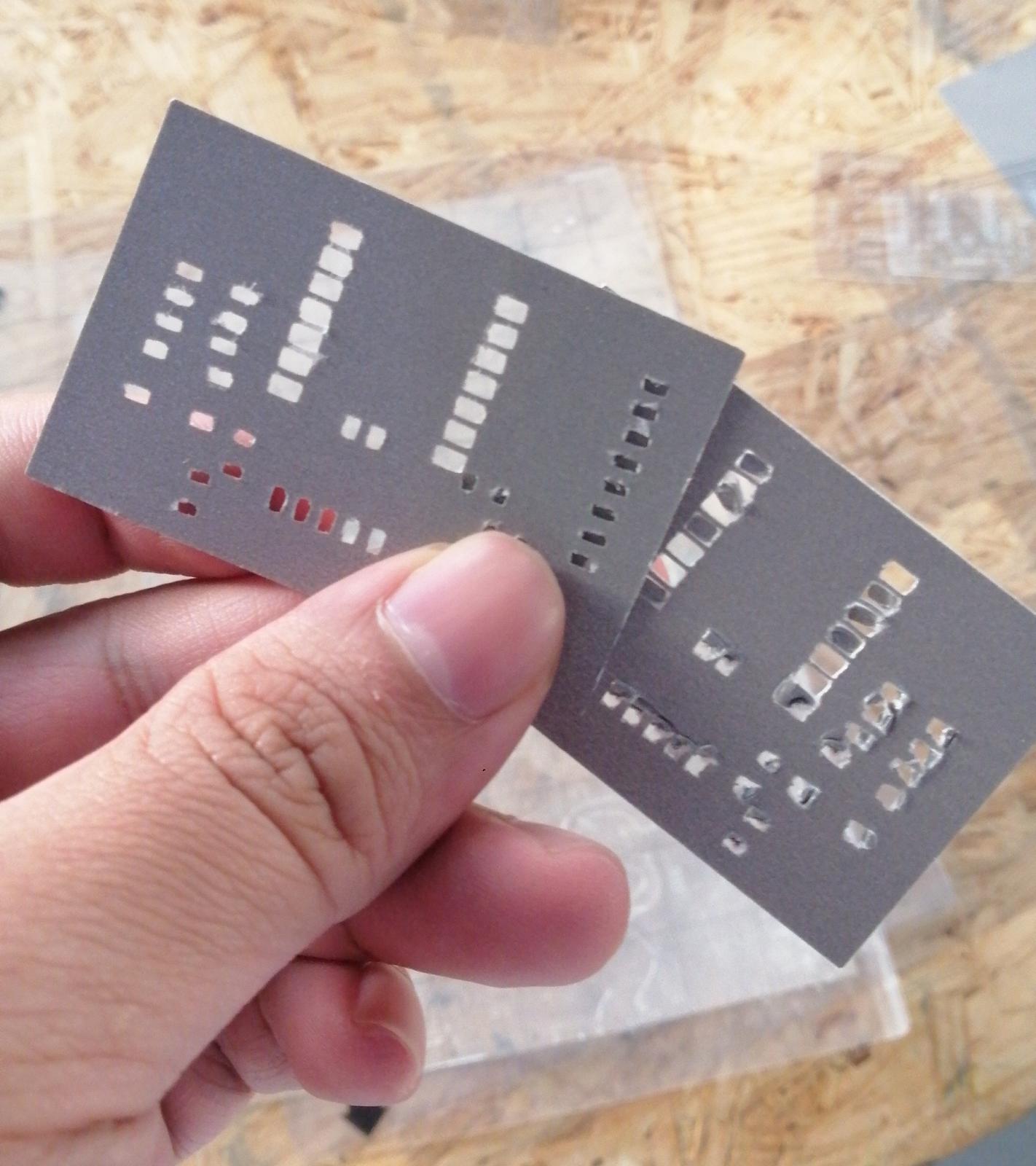
Stencil Testing
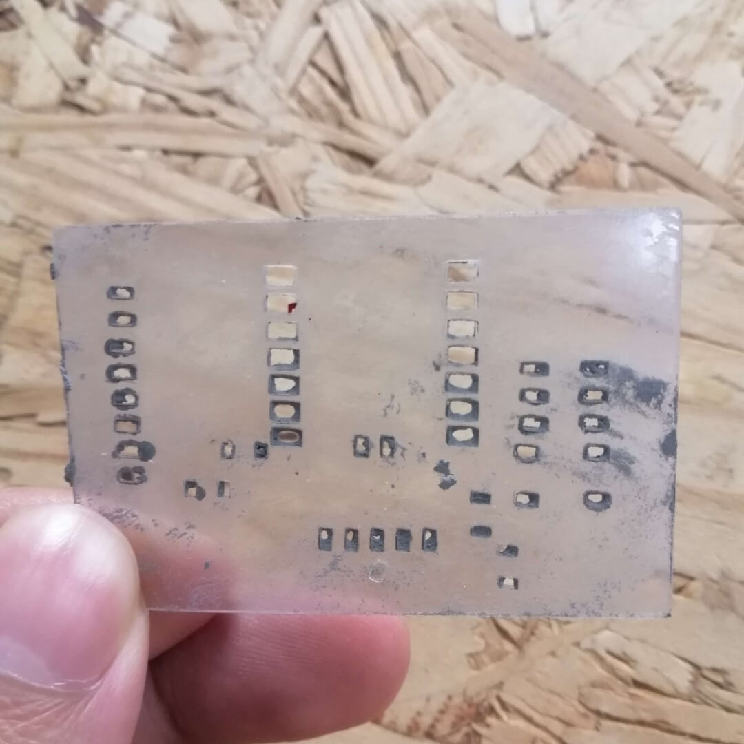
After cutting the plastic stencils it was time to test them out. Unfortunately our first test was a failure because the stencil holes where too small. As a result, the solder paste would get stuck in the holes and leave an uneven spread of paste on the pcb.
Final Sentcil
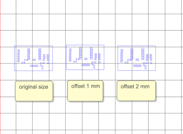
To fix this issue we tried adding an internal offset to widen the holes. We found that an offset of 2 mm was perfect but just to be safe we glued another layer of stencil to make it thicker.
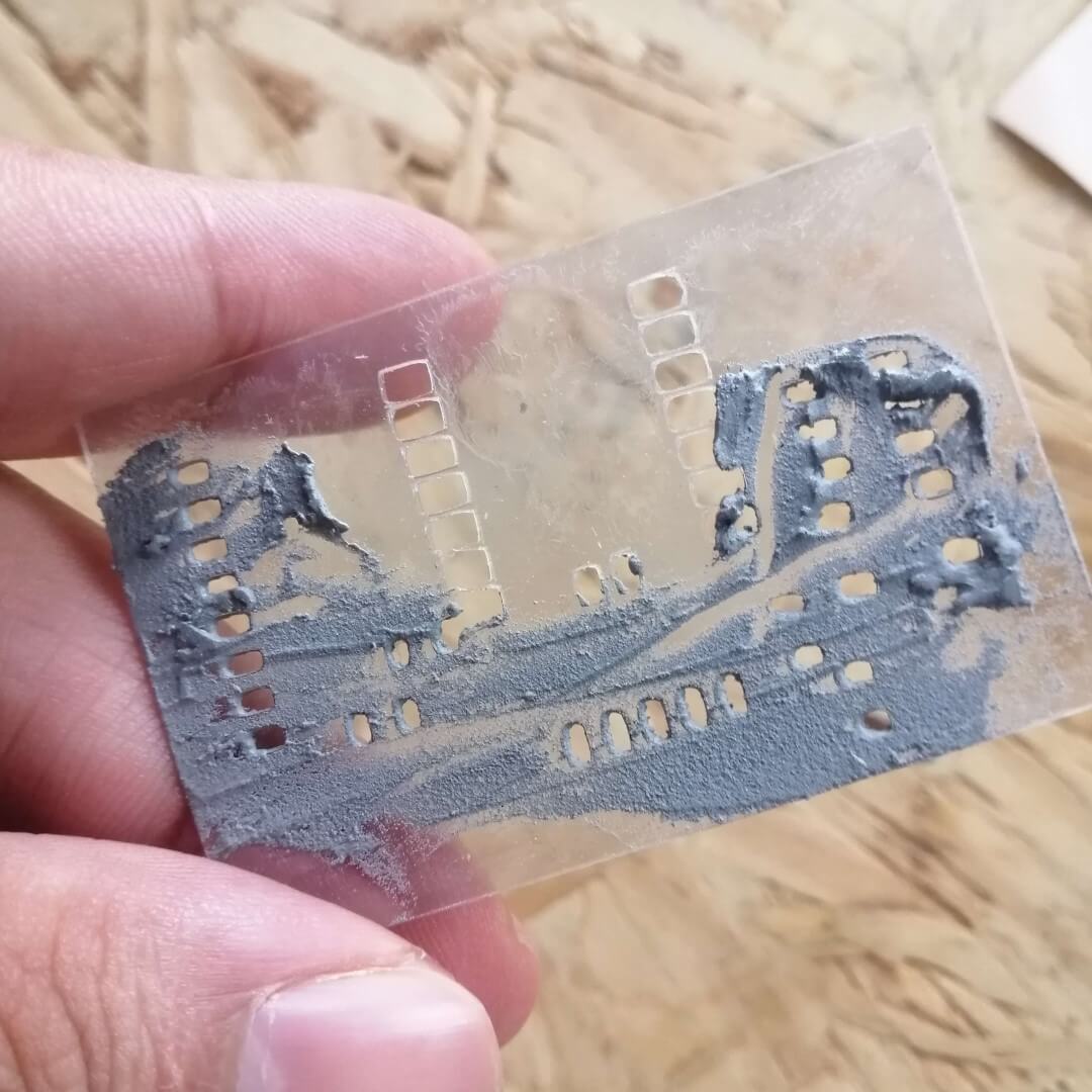
Our final stencil was a success as it spread the paste evenly on the pcb
Soldering
We were able to solder parts with a heat gun using a similar technique to the video below.
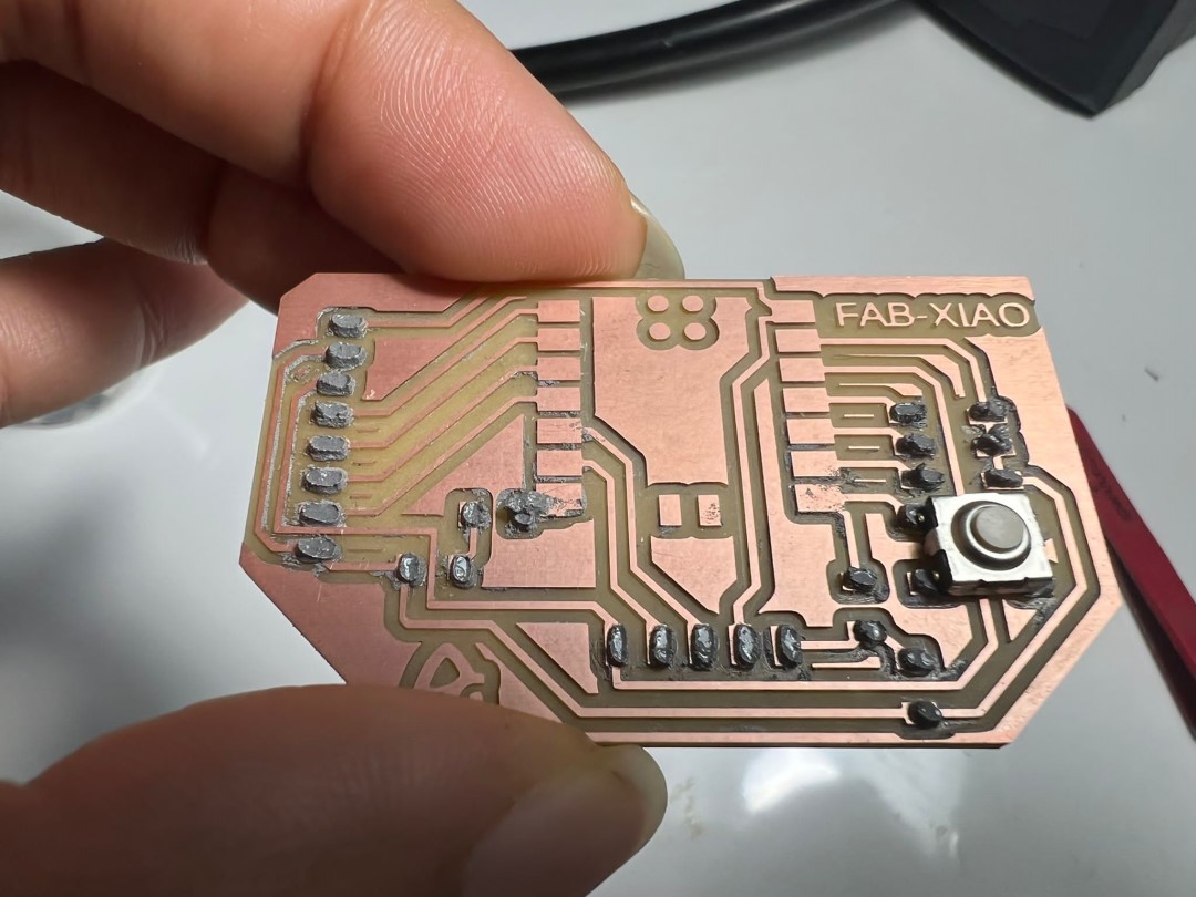
There was one minor flaw with our stencil, increasing the size of the holes created an overlap in the middle section of the stencil. Hence, that section would have to be soldered with a soldering iron. However, we still consider this project a success because 80% of the soldering was done and the rest of the work is more manageable because of the stencil.
The is an image of the pcb after soldering most of the parts.
Design Changes (optional)
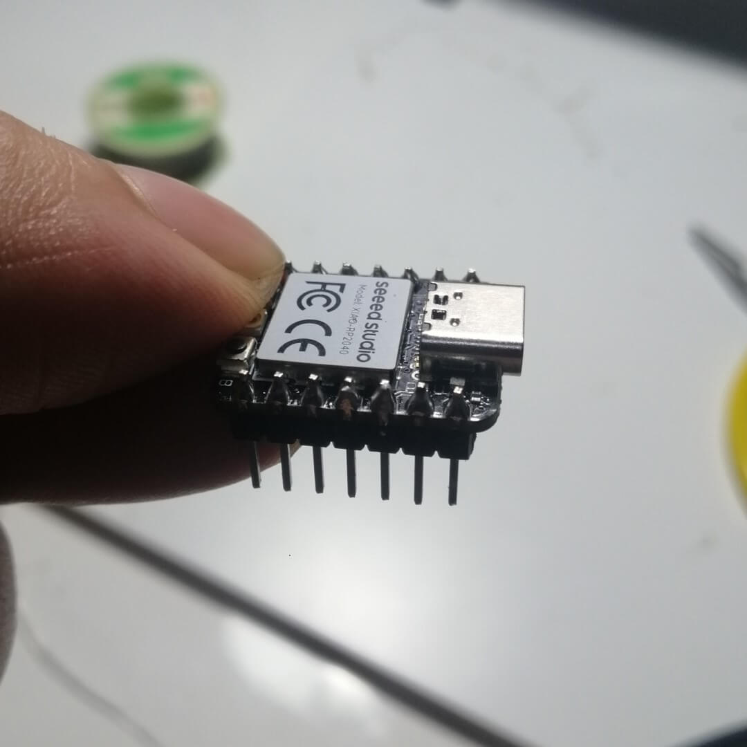
In the original project that Adrian Torres did the microcontroller chip was directley soldered on the pcb (refer to the introduction section ). This is not a bad idea if you want to only use the chip for this project alone. However, we would like to be able to use the chip in other projects so we need to make some changes to the design.
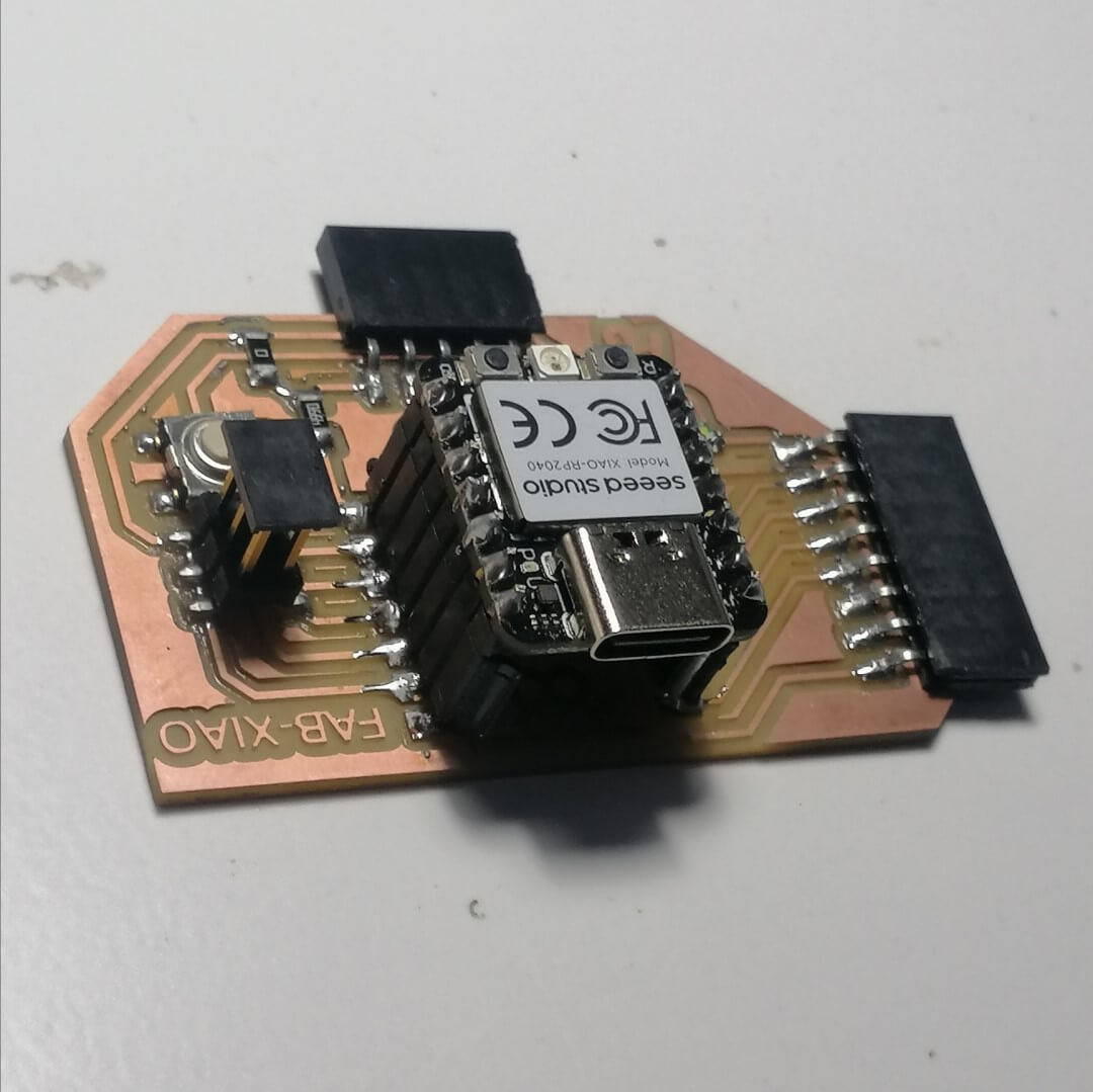
We added male and female pins to allow the microcontroller chip to be removed if needed.
This is what the microcontroller looks like with the pins soldered
Note
It is recommended to create holes in the pcb where the solder tabs are ahead of time to make soldering pins easier. This was a mistake on our part and made the process more difficult than it had to be.
!!!
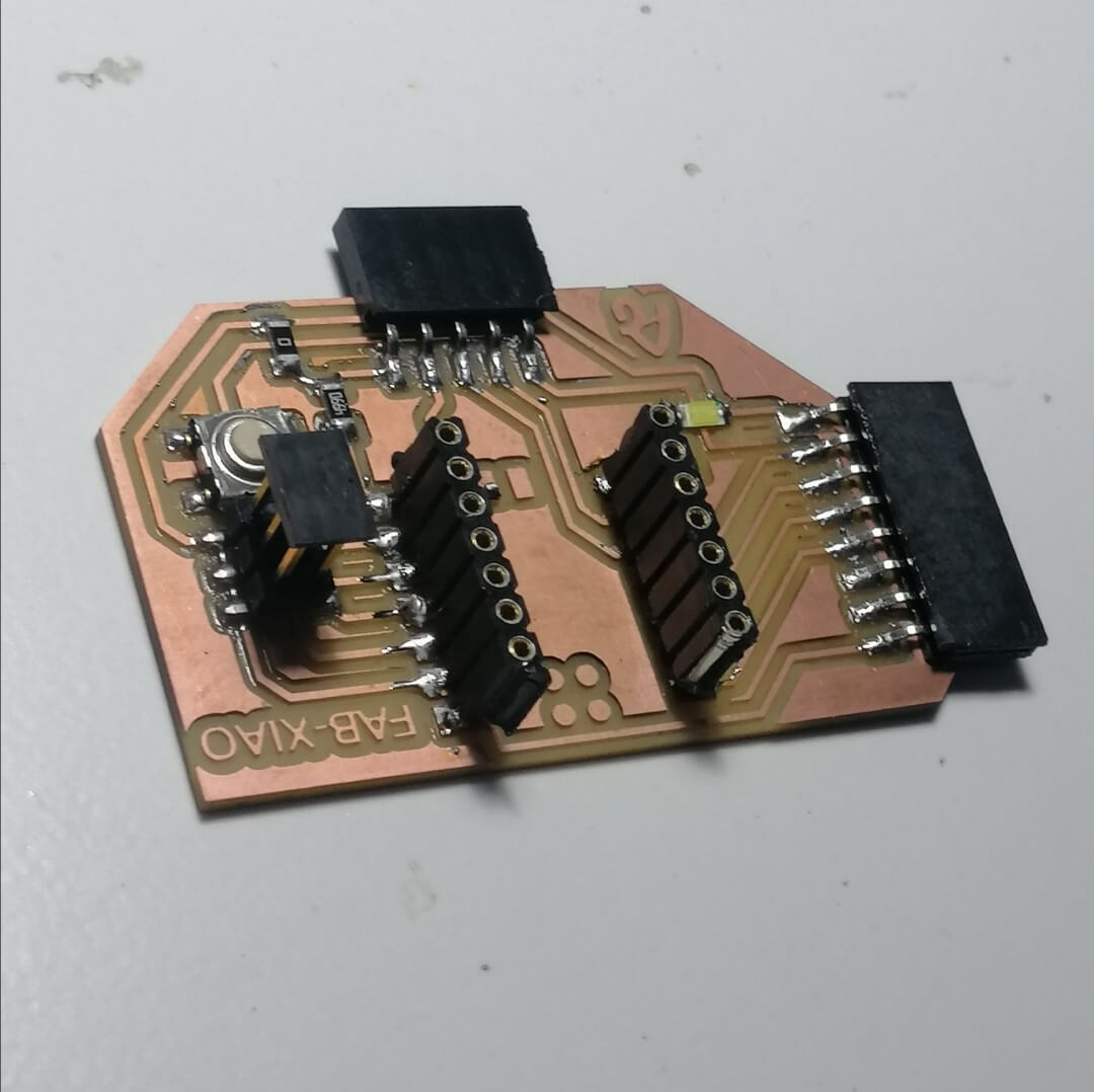
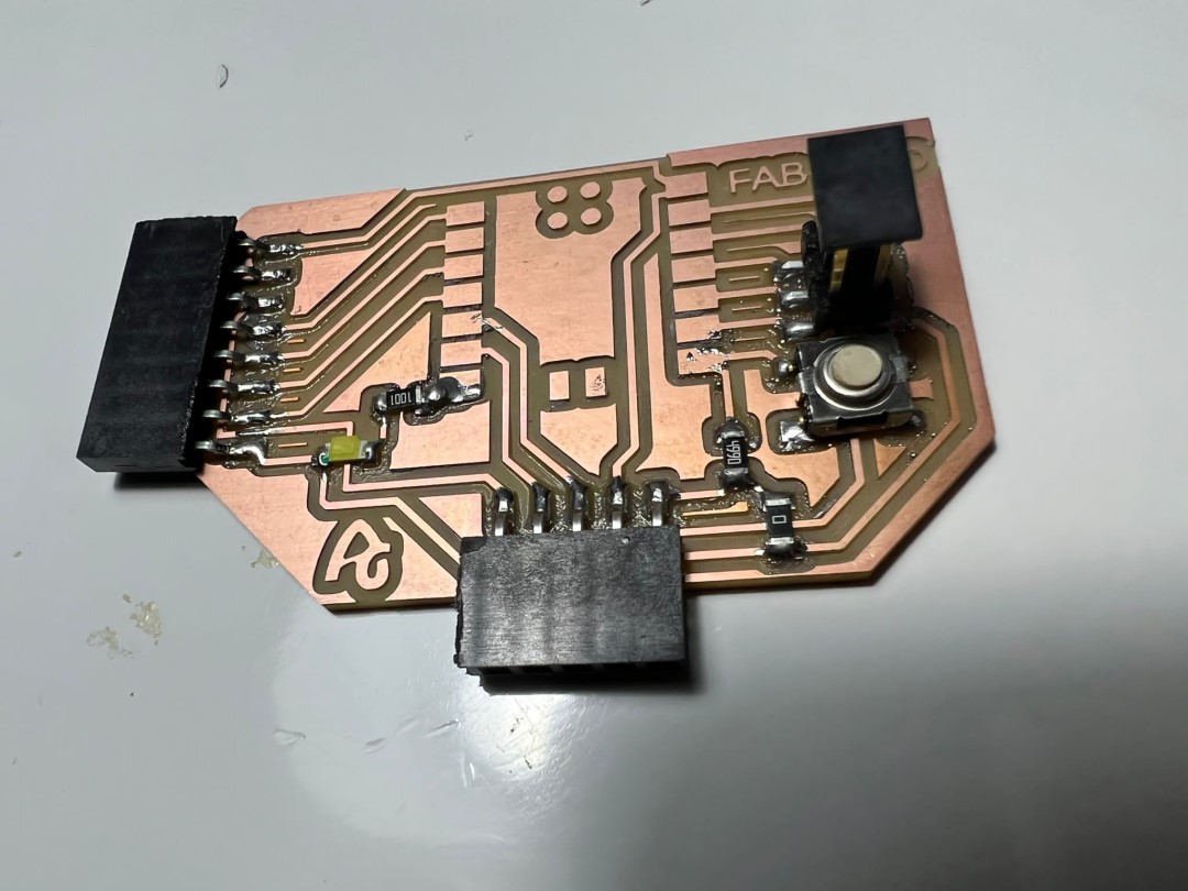
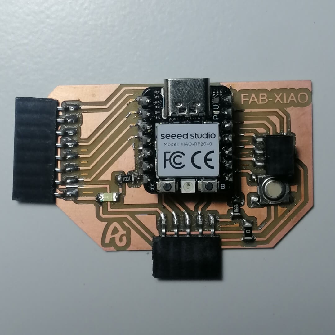
Final Result
After soldering all the parts the board looked like this
Board Testing
Blink
/*
 Turns an LED on for one second, then off for one second, repeatedly.

*/

// the setup function runs once when you press reset or power the board
void setup() {
  // initialize digital pin LED_BUILTIN as an output.
  pinMode(D6, OUTPUT);
}

// the loop function runs over and over again forever
void loop() {
  digitalWrite(D6, HIGH);   // turn the LED on (HIGH is the voltage level)
  delay(1000);                       // wait for a second
  digitalWrite(D6, LOW);    // turn the LED off by making the voltage LOW
  delay(1000);                       // wait for a second
}
Button W/ LED
/*
Turns on and off a light emitting diode(LED) connected to digital pin D6,
  when pressing a pushbutton attached to pin D7.
*/
// constants won't change. They're used here to set pin numbers:
const int buttonPin = D7;     // the number of the pushbutton pin
const int ledPin =  D6;      // the number of the LED pin

// variables will change:
int buttonState = 0;         // variable for reading the pushbutton status

void setup() {
  // initialize the LED pin as an output:
  pinMode(ledPin, OUTPUT);
  // initialize the pushbutton pin as an input:
  pinMode(buttonPin, INPUT);
}

void loop() {
  // read the state of the pushbutton value:
  buttonState = digitalRead(buttonPin);

  // check if the pushbutton is pressed. If it is, the buttonState is HIGH:
  if (buttonState == HIGH) {
    // turn LED on:
    digitalWrite(ledPin, HIGH);
  } else {
    // turn LED off:
    digitalWrite(ledPin, LOW);
  }
}