3. Computer controlled cutting
This week I worked on using the Vinyl & Laser Cutter.
Vinyl
Setup
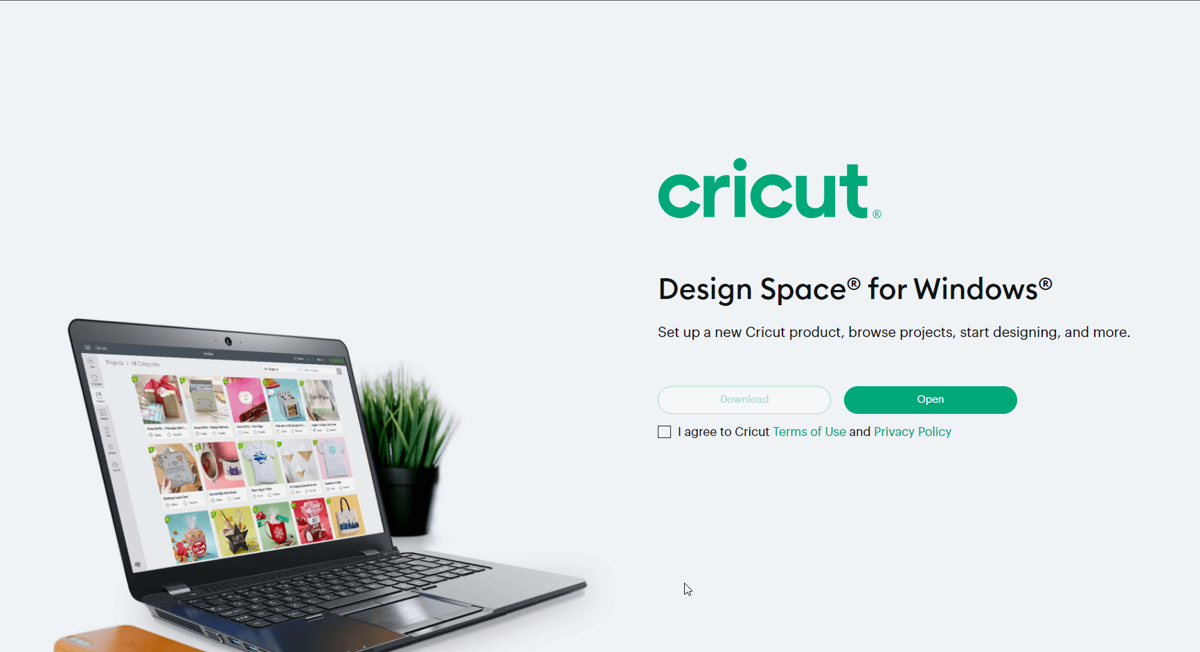
Download the cricut software
from here.
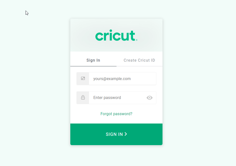
 Login to your account or signup if you dont have one
Uploading Designs
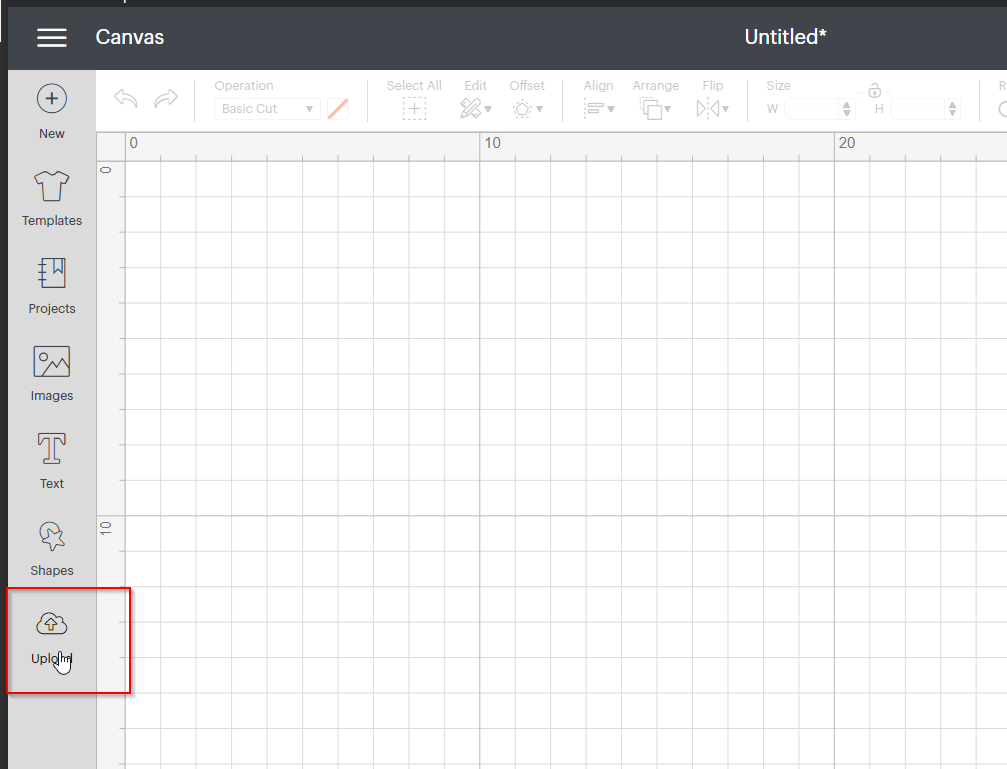
click the upload button
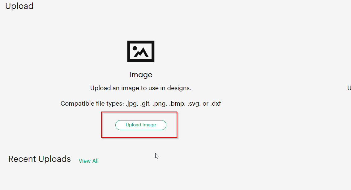
 upload a design
Background Remover
In this screen you can remove any elements you want from the design
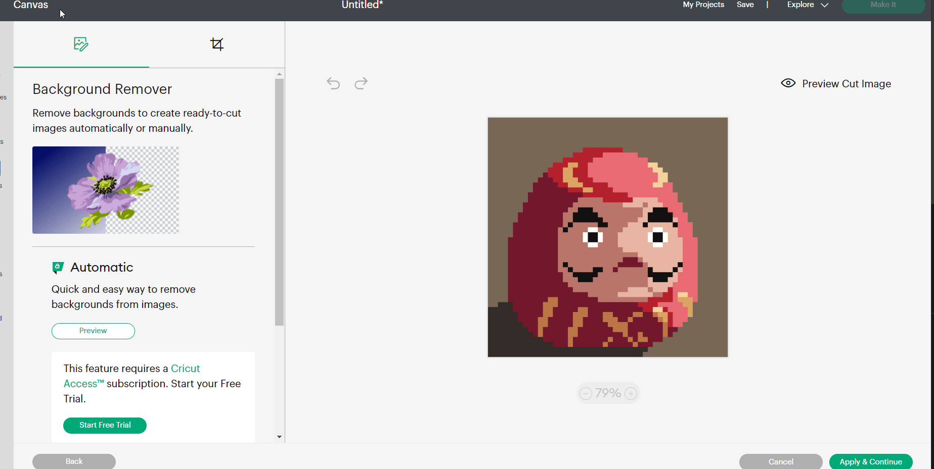
You can preview what the design it will look like by pressing the preview button
Keep in mind that the design will be cutt in one color

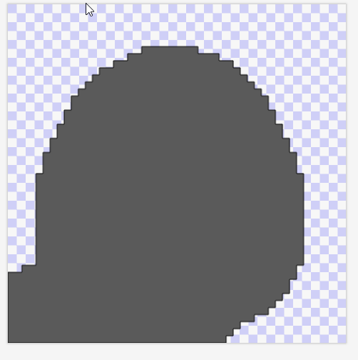
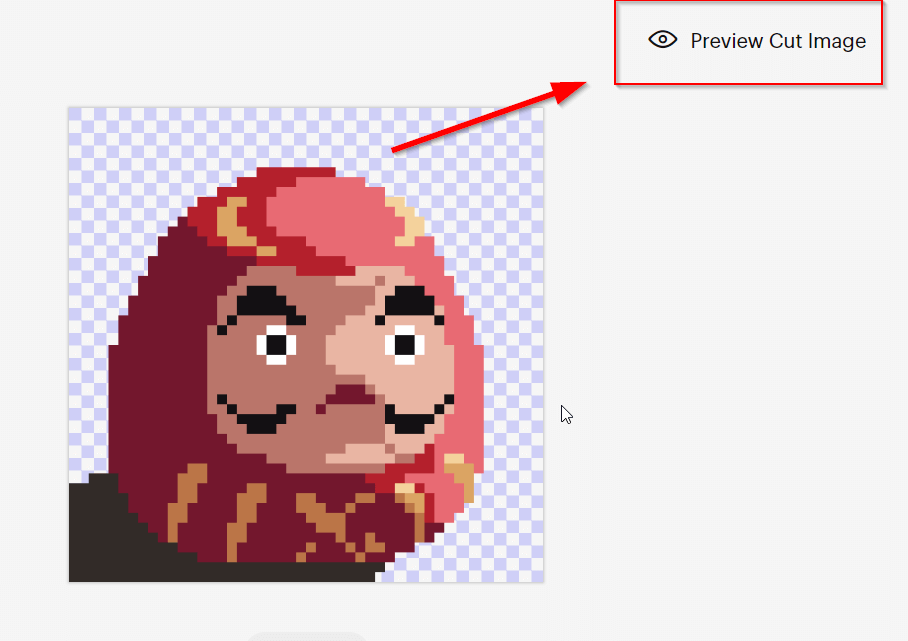
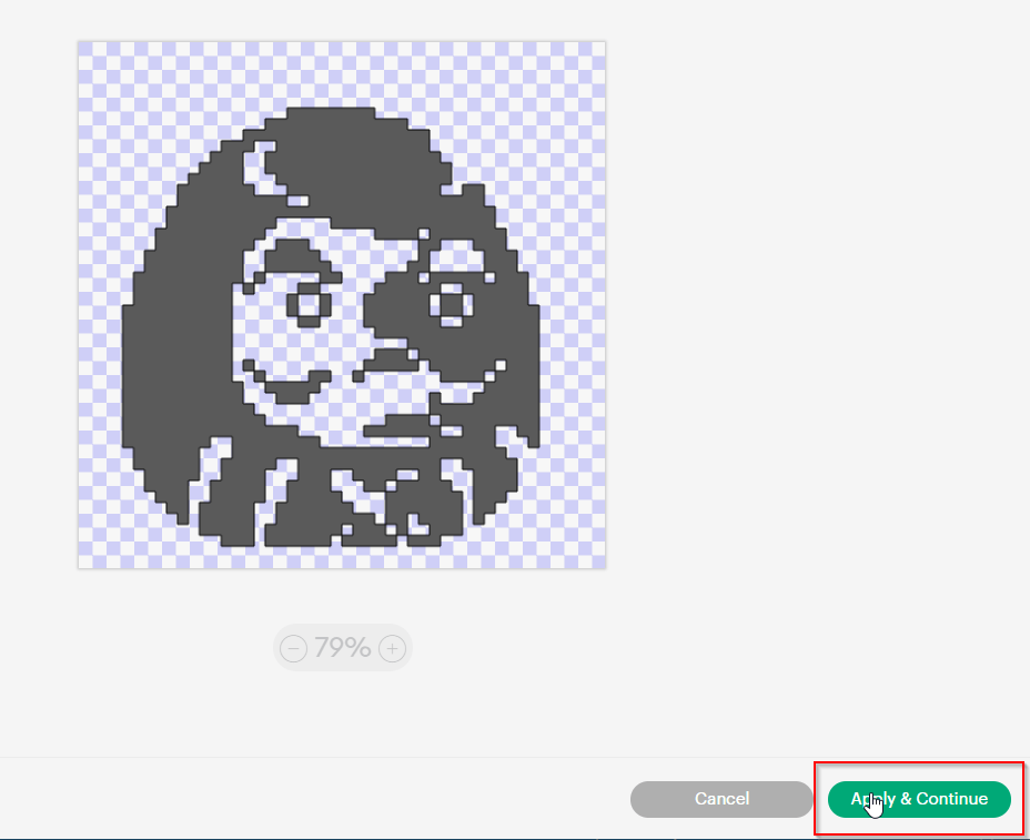
As you can see we need to remove more elements to make it more clear. Once satisfied click apply and continue.
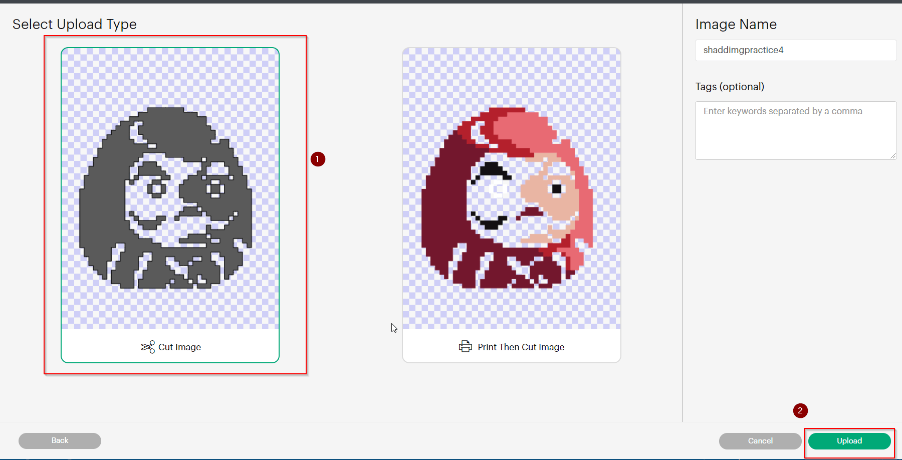
Adding Design to Canvas
Select cut image then upload
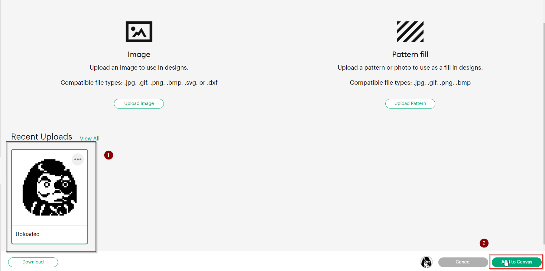
 select the design then upload to canvas
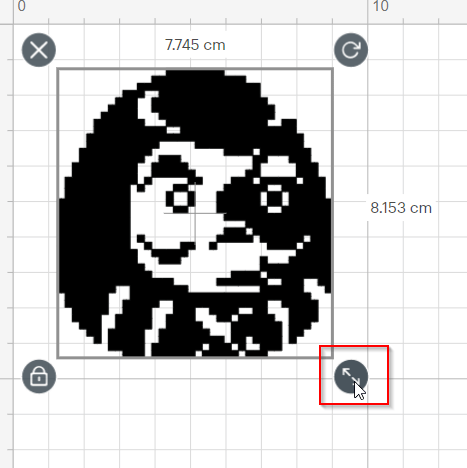
Edit Design and Finalize
Adjust the design size using the arrows on the corner
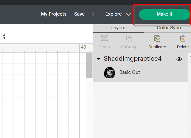
Click the Make It button to finalize the design proccess and go to the vinyl cutting phase.
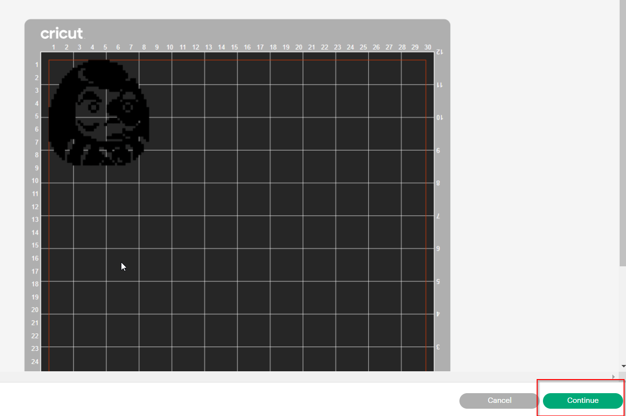
 This screen will show the dimentions of your design click continue once satisified
Vinyl Cutting Machine
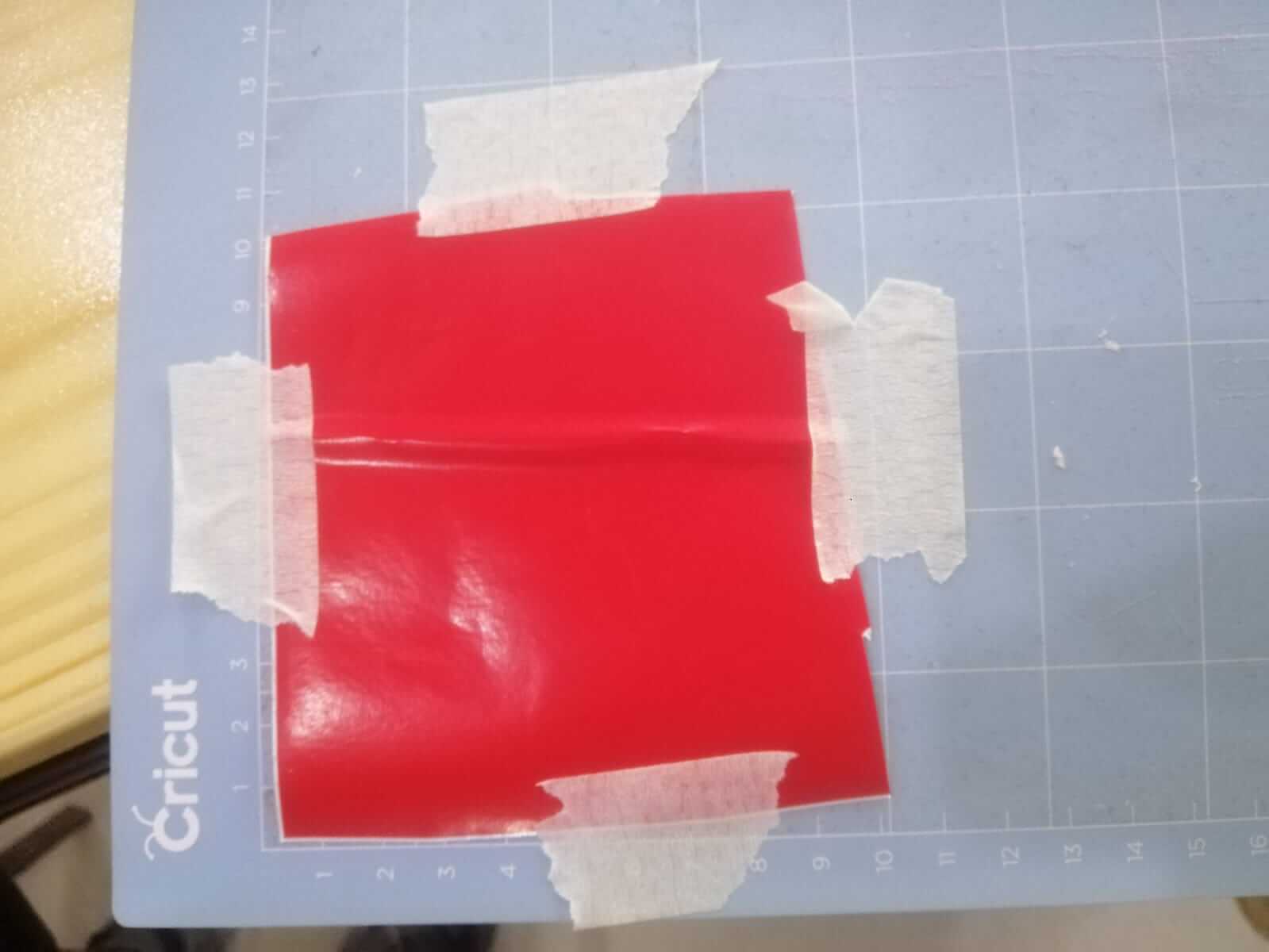
Cut some vinyl paper with the same dimentions of your design
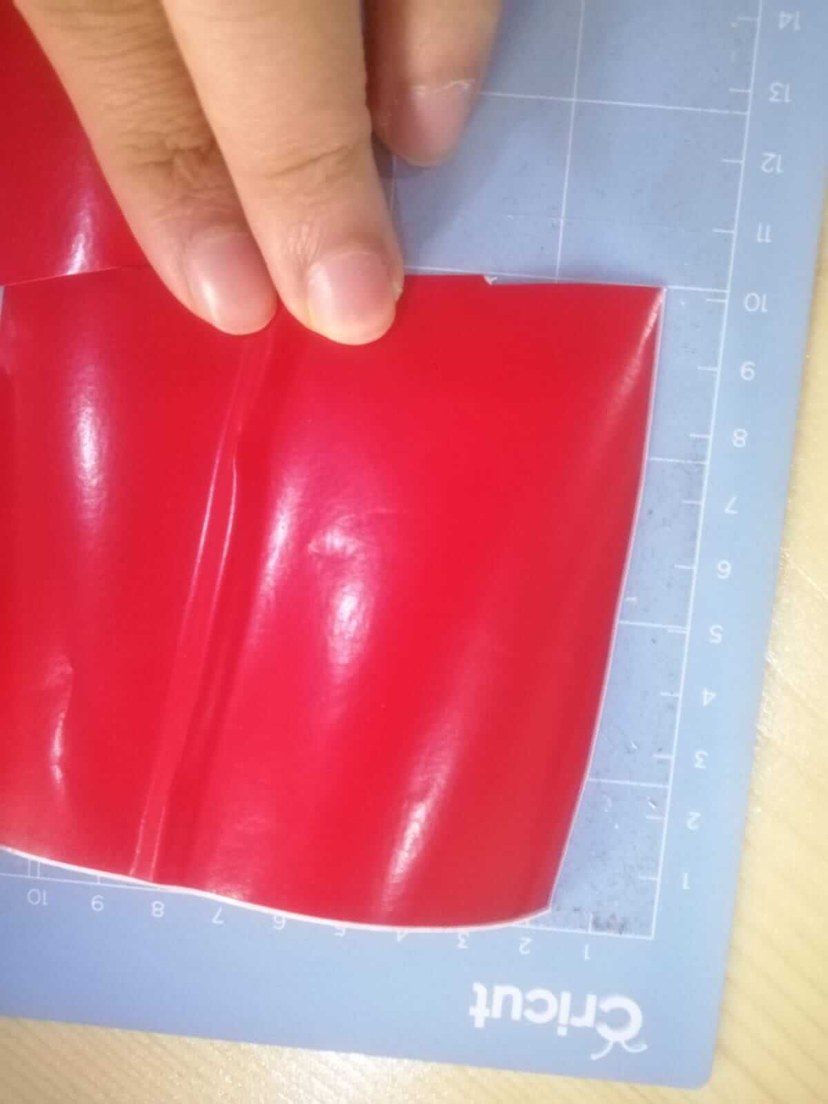 Tap the vinyl paper so that it doesn’t move when the machine is cutting
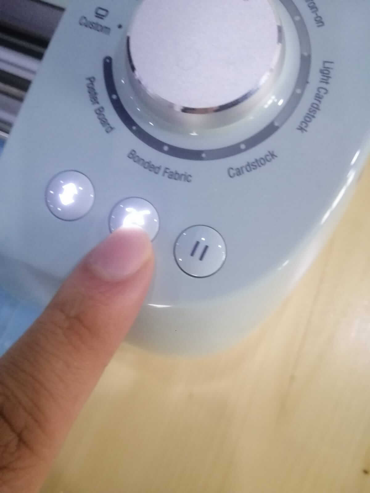
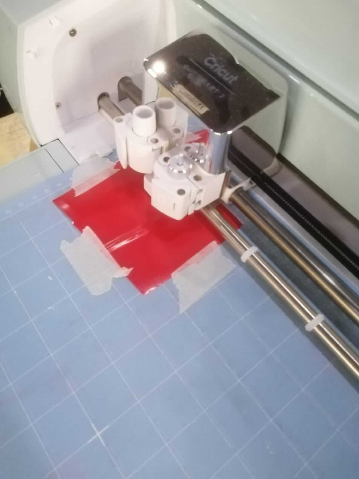
connect your pc to the vinyl cutter then press this button to begin the cutting process
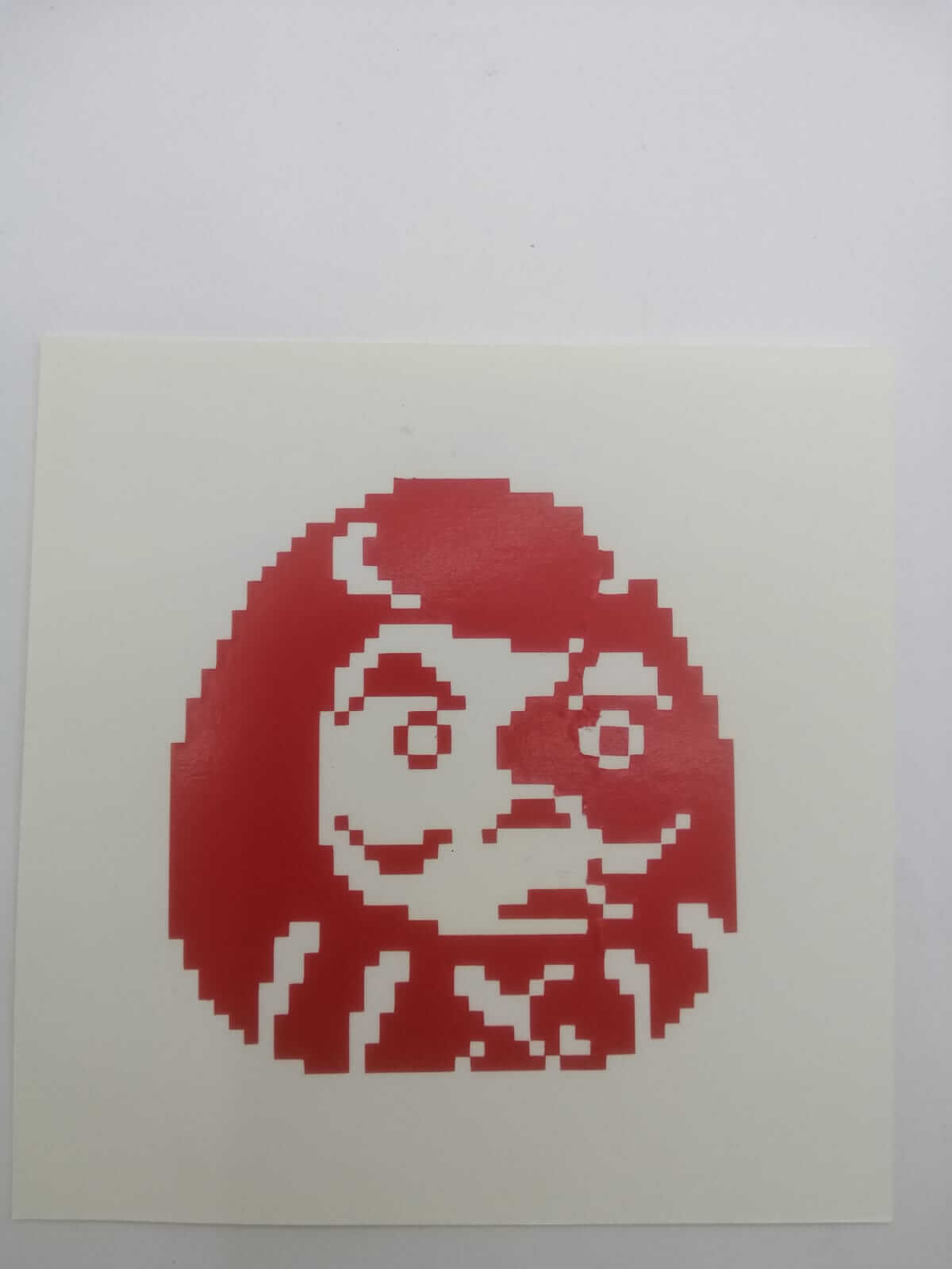
Result
this is the final result
Laser Cutter
Operating Laser
Setup (Group Assignment)
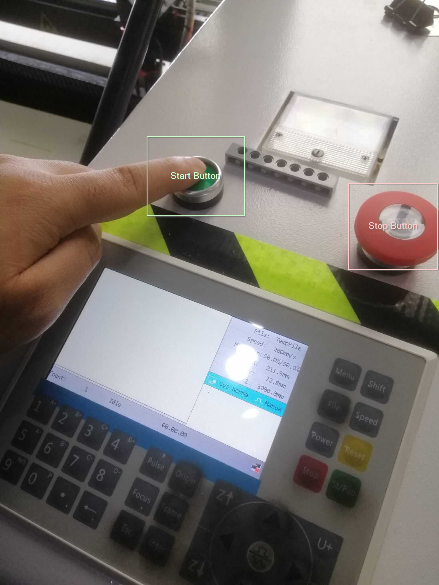
To turn on the laser machine press the start button and to stop the machine you can press the stop button
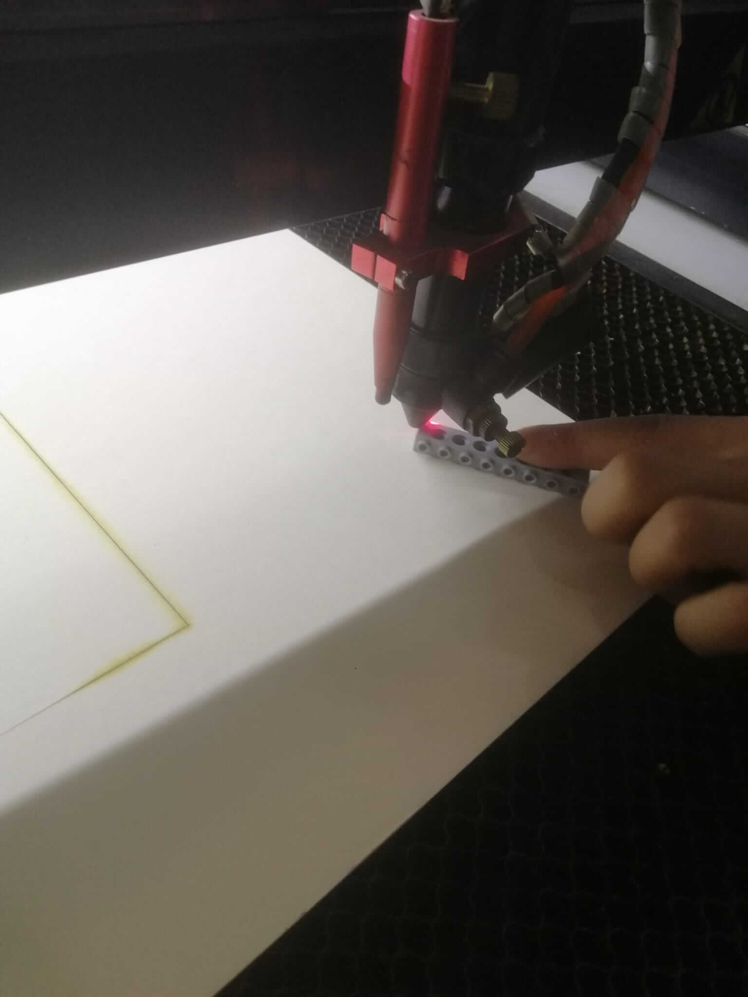
There needs to be a distance between the laser and the cutting board. That distance can be estimated using the height reference tool.
Movement and Origin
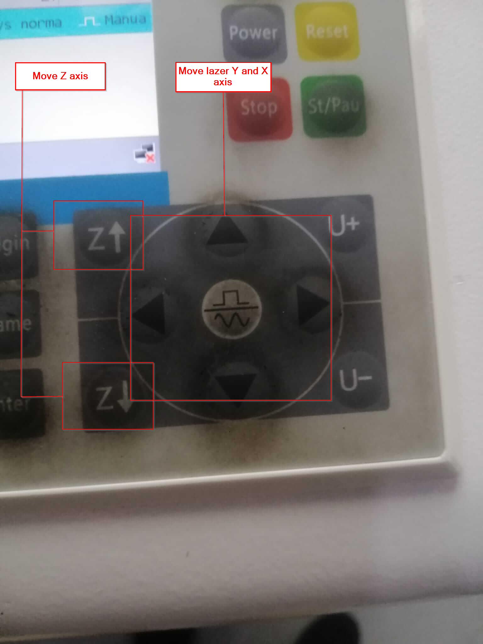
You can use the the arrow buttons to move the laser and the Z buttons to move the surface under the laser.
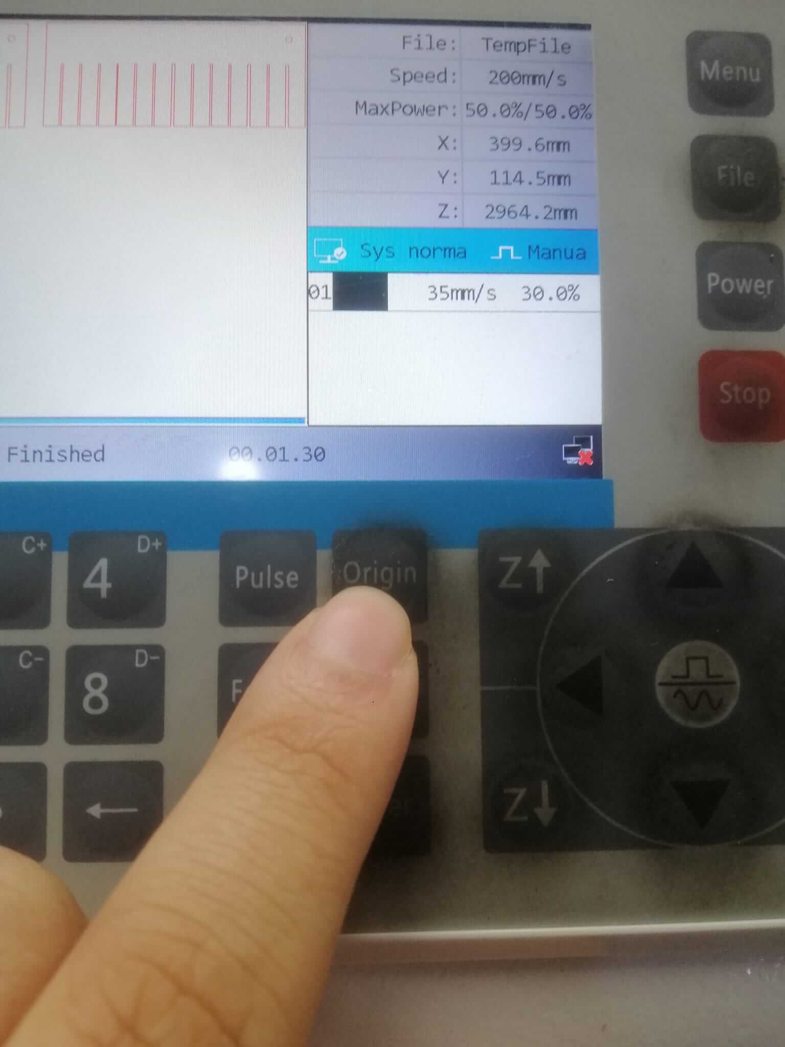
The laser will always start cutting form the origin point.
You can reset the origin point by pressng the Origin button.
Transfering Designs to Laser
You can transfer designs to the laser machine by connecting it to a PC.
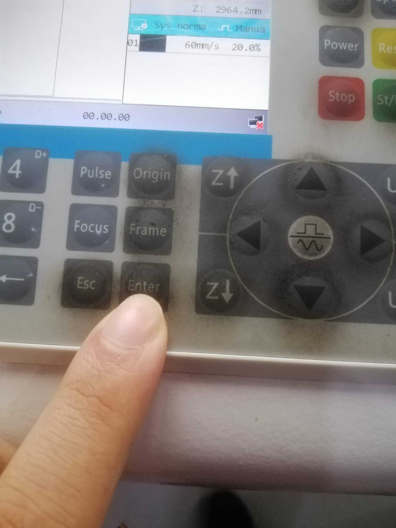
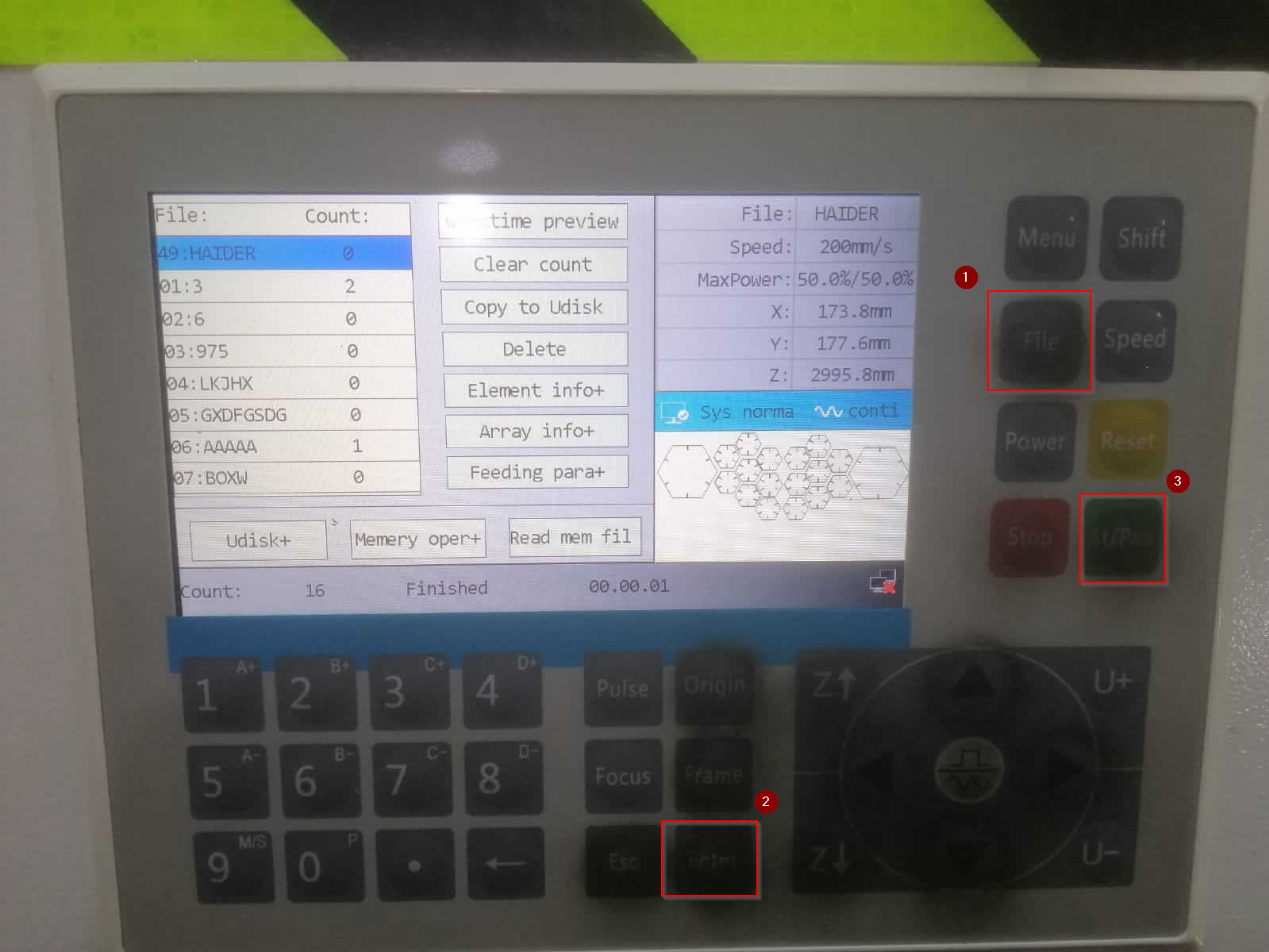
Once files haven been transfered you can click on the File button
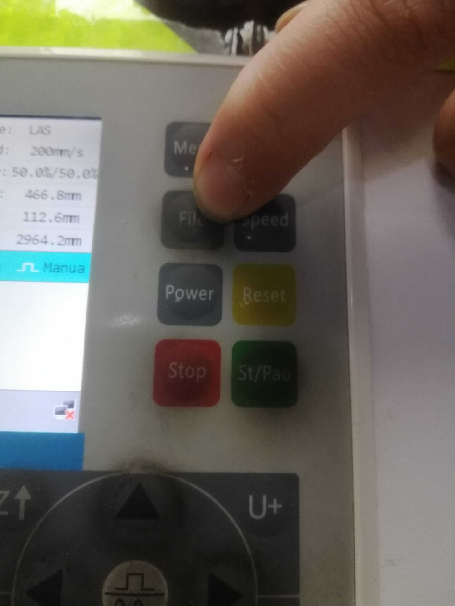
Navigate the design file you want then press the Enter button to select it.
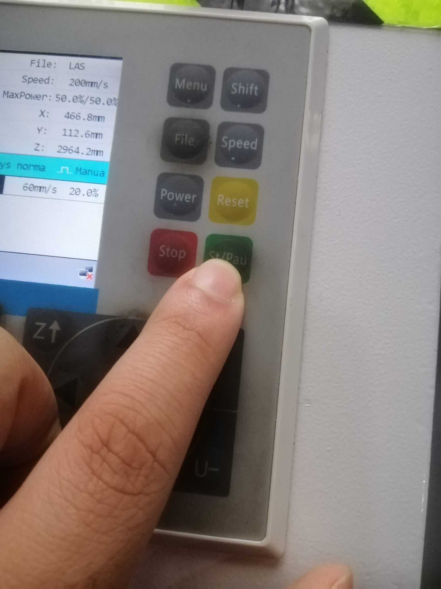
 Press the St/Pau button to start the laser cutting process
Testing Material
The laser must be calibrated according to the material you want to cut. The table below shows that parameters that can be changed on the laser and what they do.
| Parameter | Description |
|---|---|
| Power | How strong the laser beam is |
| Speed | How fast the laser cuts |
| Focal | Determines how wide the line the laser cuts |
| Repitions | How many times the laser goes aroud the path specified |
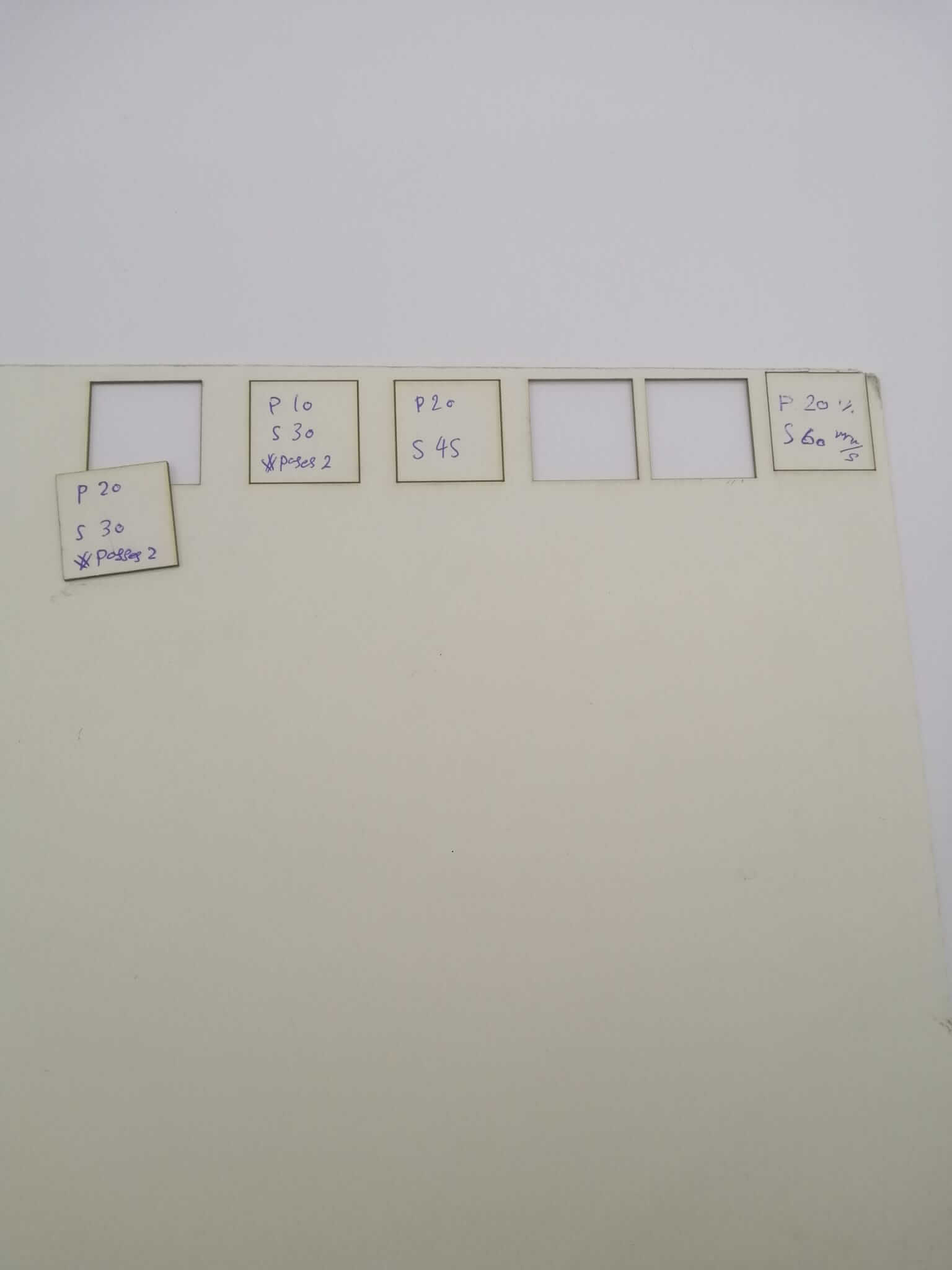
The image bellow shows different tests done with different parameters.
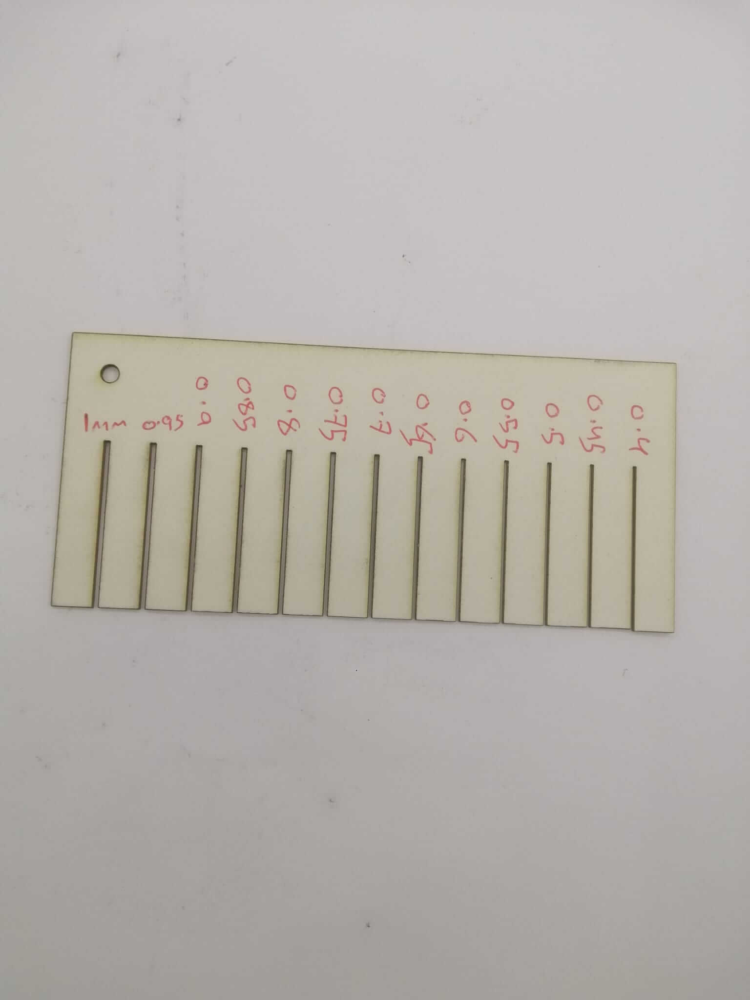
 we can also test joint thickness for press fit projects. We can test to see what is the right thickness press fit pieces need to be to fit correctly.
Press Fit Kit
Design
I used this youtube tutorial to help me click
2D Sketch
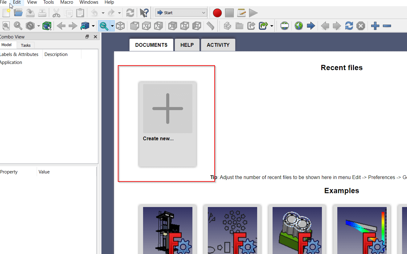
To start I opened freeCAD and created a new project.
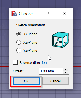
I created a sketch using Sketch> Create Sketch
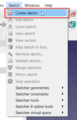
Click okay
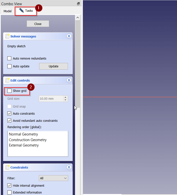
I created a grid by going to tasks then checking the show grid option
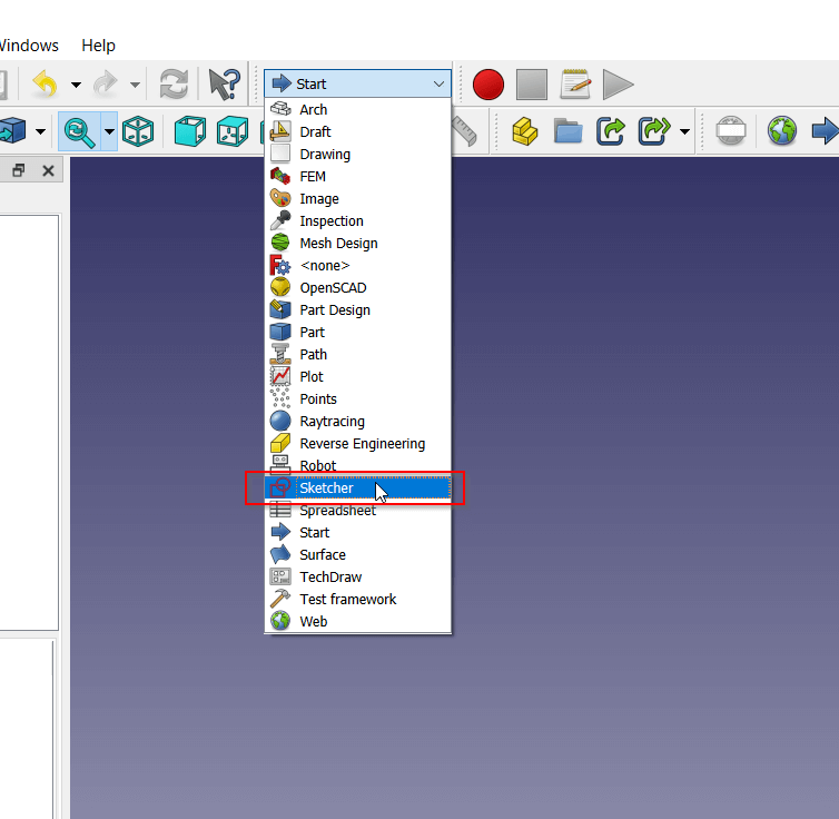
I selected the sketcher tool
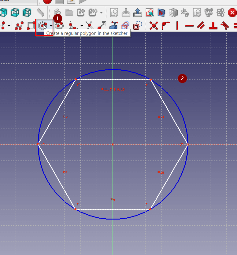
 I selected the polygon tool the created a hexagon in the center of the grid.
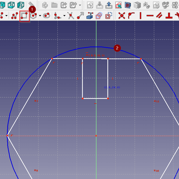
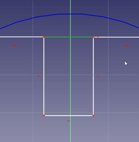
 Using the square tool i created a square on one of the hexagons sides. This will later be a joint that will help us join different pieces together.
Note
If you are having trouble doing this step delete some constraints or use the trim tool (third tool to the right)
I selected the intersection between the hexagon and the square and deleted it.
Parametric Design Spreadsheet
In this section I created a parametric table. In this table i will put all of the different parameters that i will use in the design. This is important because we want things like joint height and width to be constant. This also allows us to update all the joint dimentions by simply changing the values in the parametric table.
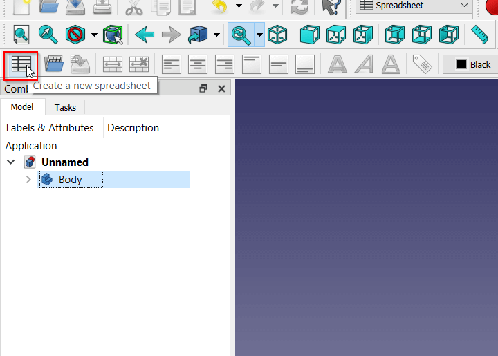
You can access the parametric table on freeCAD by going to spreadsheet
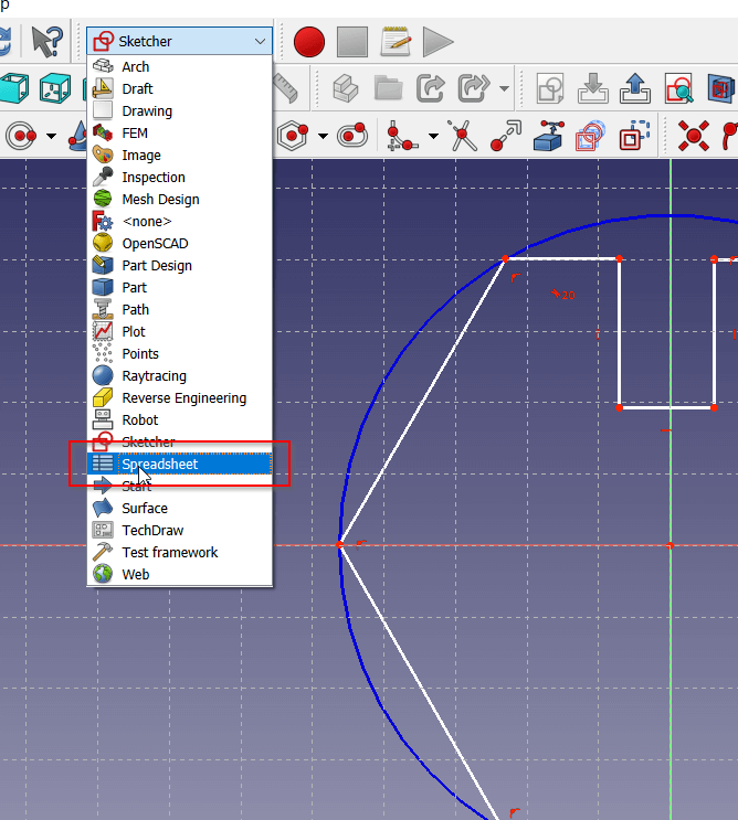 Create a spreadsheet.
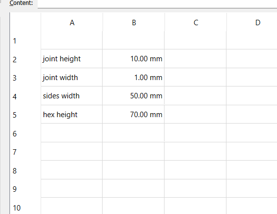
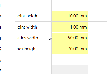
 I put the names of the parameters on the first field and its values in the second field.
Tip
You can make the value fields alone and it would work. However its easier to understand the data when we put the names next to the values.
Select a value , right click > properties.
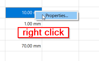
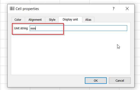
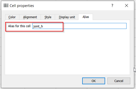
Put the unit of measurement in unit string (for this example we used mm - millimeter ). Put the name of the parameter in the alias section, the alias is what we will use to access the value.
 repeat the steps until all of the value fields are highlighted yellow.
Constraints
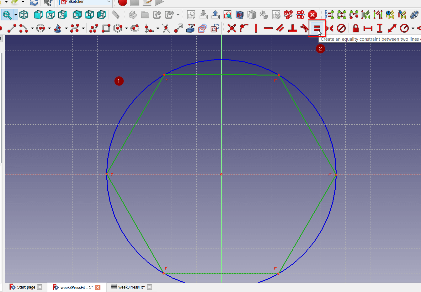
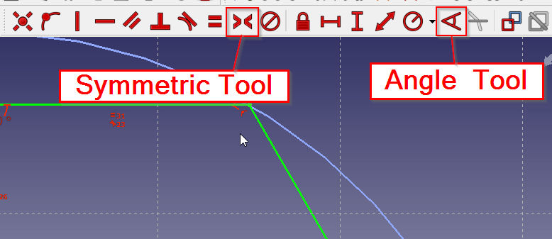
Select all the sides of the hexagon then select the Equality Constraint. This will makes sure that if one side changes the rest of them will resize to match.
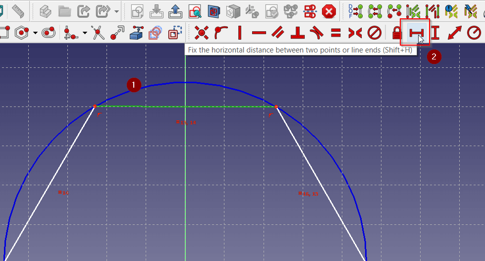
Select one side then Horizontal Distance Constraint. This will allow us to determine the length of this side.
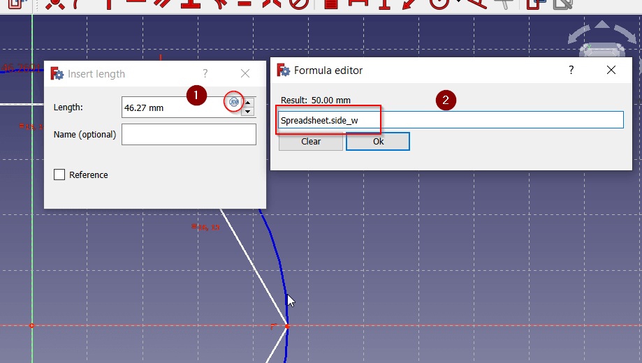
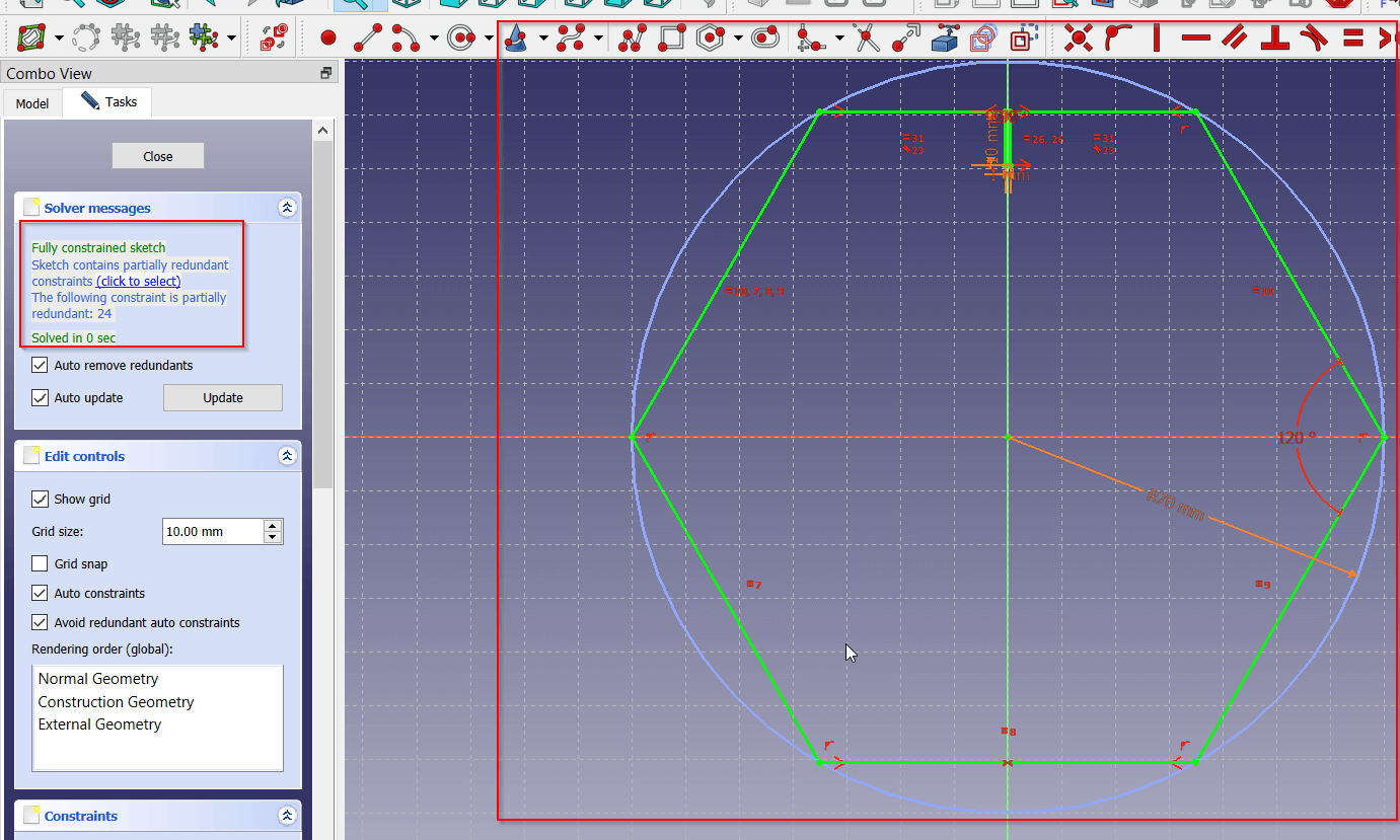
 In order to use the parametric table, select the grid icon then type the name of the spreadsheet (in this example its named Spreadsheet) followed by a dot “.” then the name of the value you want to use (in this example side_w).
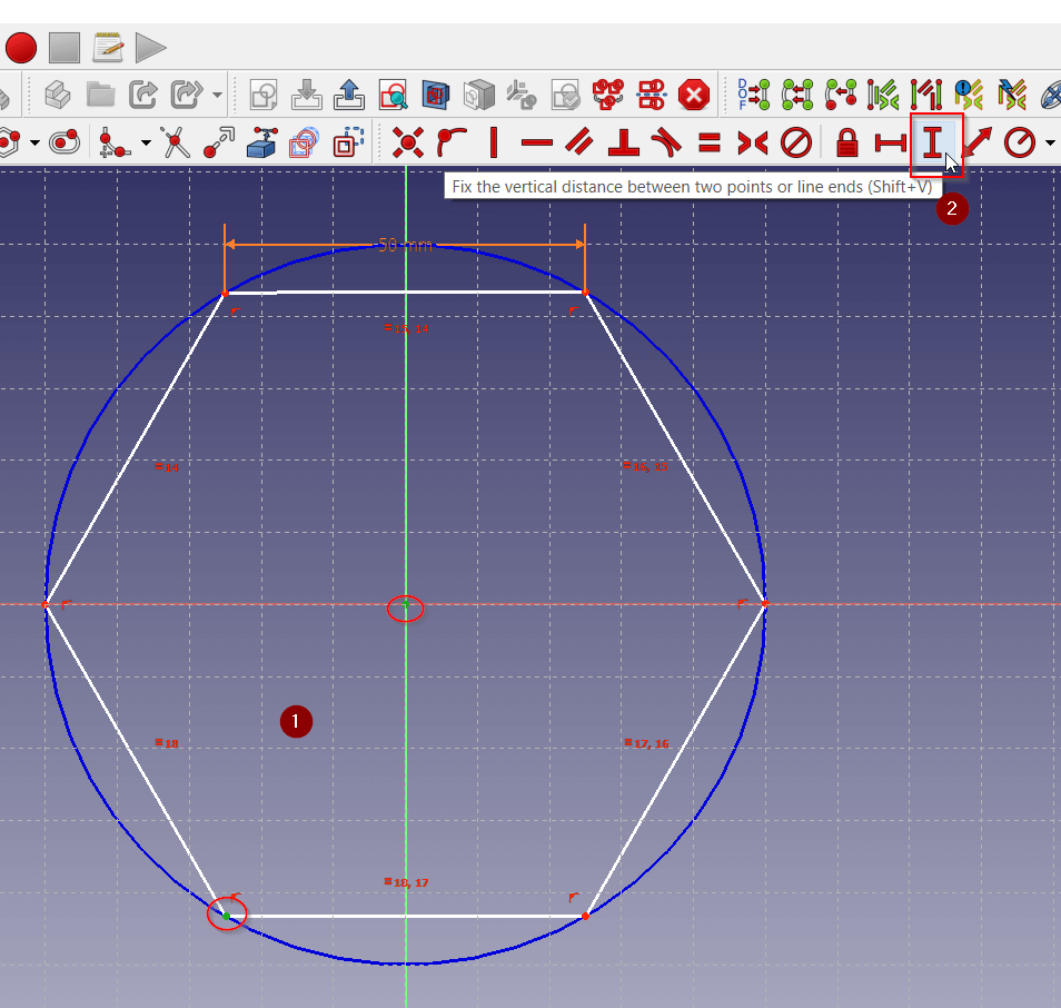
You can do the same process with vertical points by using the Vertical Distance Constraint. In this example I used it to set the distance between the midpoint and a corner.
There are more constraint tools that can help you.
You can refer to the offical FreeCAD Documentation to learn more about this constraint tools.
You should aim for your design to be fully constrained by checking the task section on the left or seeing that the entire sketch is green.
Body
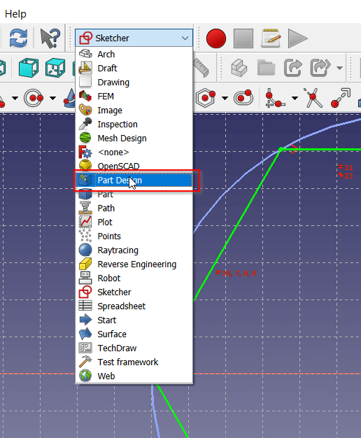
Select the Part Design to access the 3d tools.
To duplicate the joint on the other sides select Add Pad button.
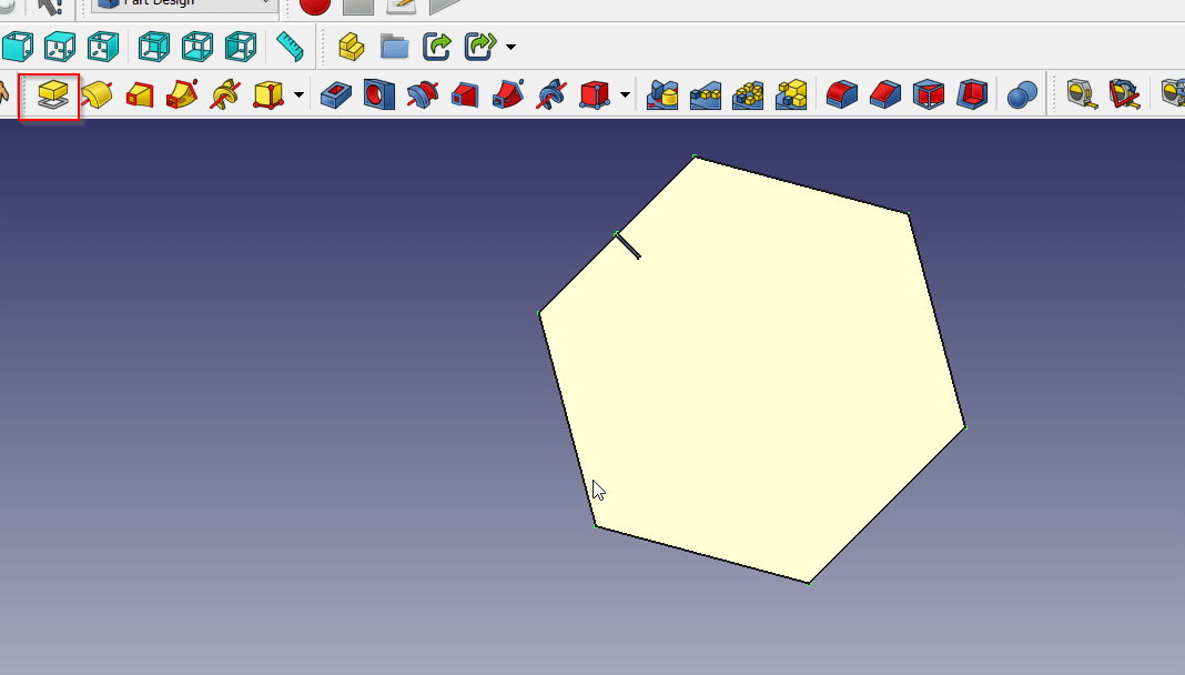
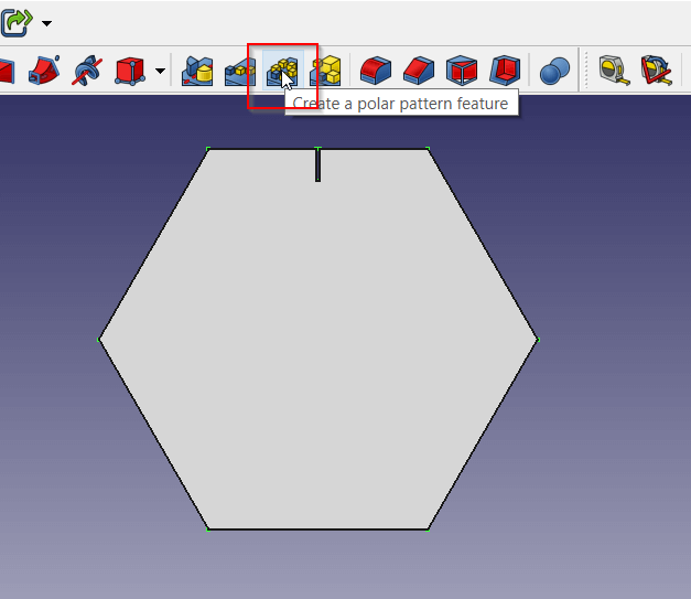
Click the Polar Pattern.
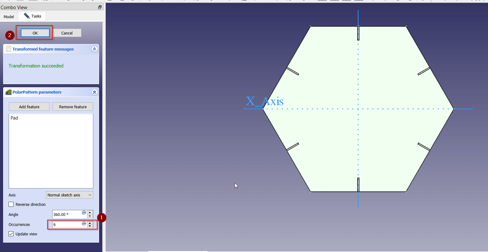
Select the number of repitions then click OK.
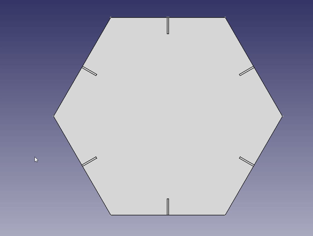
Final Design
This is the final result
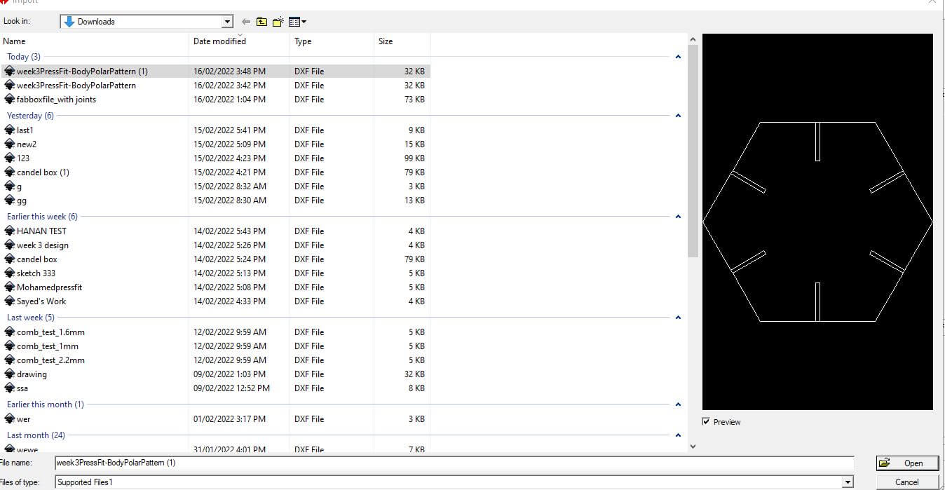
 You can download the design file from here
or a dxf file from here
You can download the design file from here
or a dxf file from here
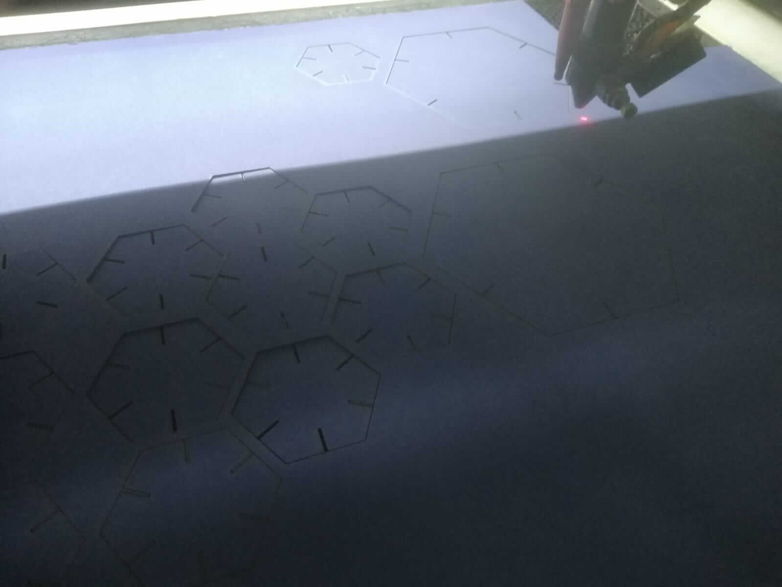
Development
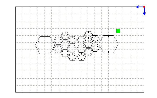
Import your design on the laser software.
You can copy and paste the part serveral times
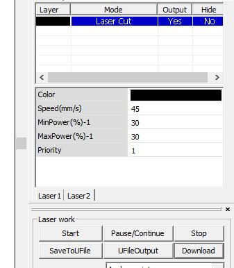
You can adjust the lasers settings from this menu.
The table below shows the different parameters availble to change and what happens to the laser when you change them.
| Parameter | Its Effect on the Laser |
|---|---|
| Power | Power controls how hot the laser beam is. Keeping this parameter too low and the laser wont cutt the material. On the other hand, if it is too high it will burn the material. |
| Speed | Speed is how fast the laser moves whilst cutting. Keeping this parameter too high and the laser wont cutt the material. On the other hand, if it is too low it will burn the material. |
| Focus | Focus is the distance between the laser and the material. Keeping laser too high and the laser wont cutt the material. On the other hand, if it is too low it will burn the material. |
Here are some things to consider when cutting
| Term | Definition |
|---|---|
| Frequency | It specifies the number of laser pulses per second. |
| Kerf | Extra material that is cutt because of how wide the laser beam is |
| Joint Clearance | A test to see if joints will fit with one anothor after cutting |
I mainly changed the power to 30% and speed to 45 mm/s, I kept the rest of the parameters at default.
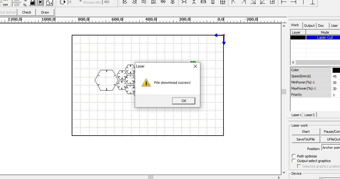
Click the download button to transfer the design to the laser machine.
Click File , select the design file then click Enter. Click the Start Button to start cutting.
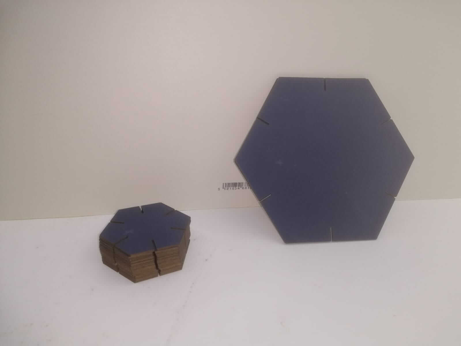
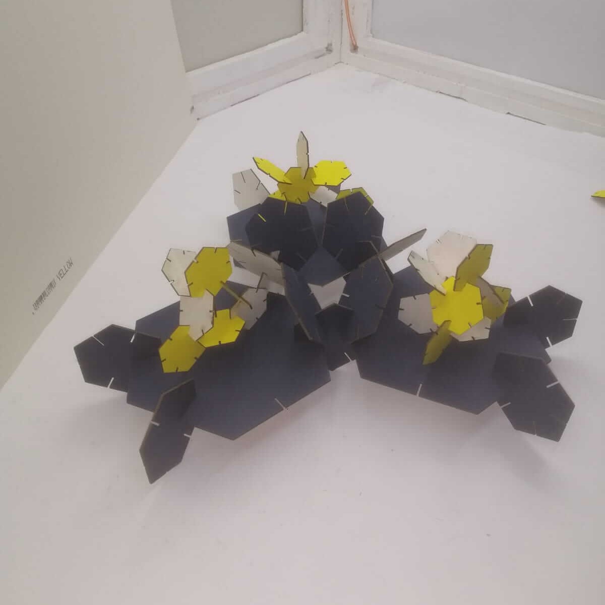
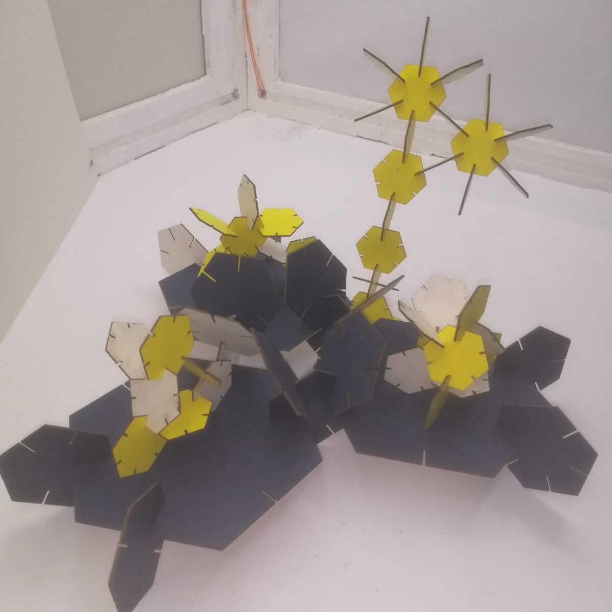
Here are some designs I made using the parts I made.
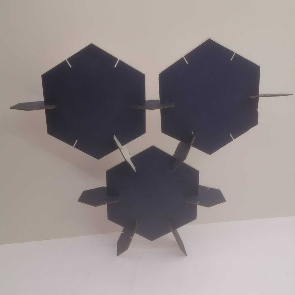
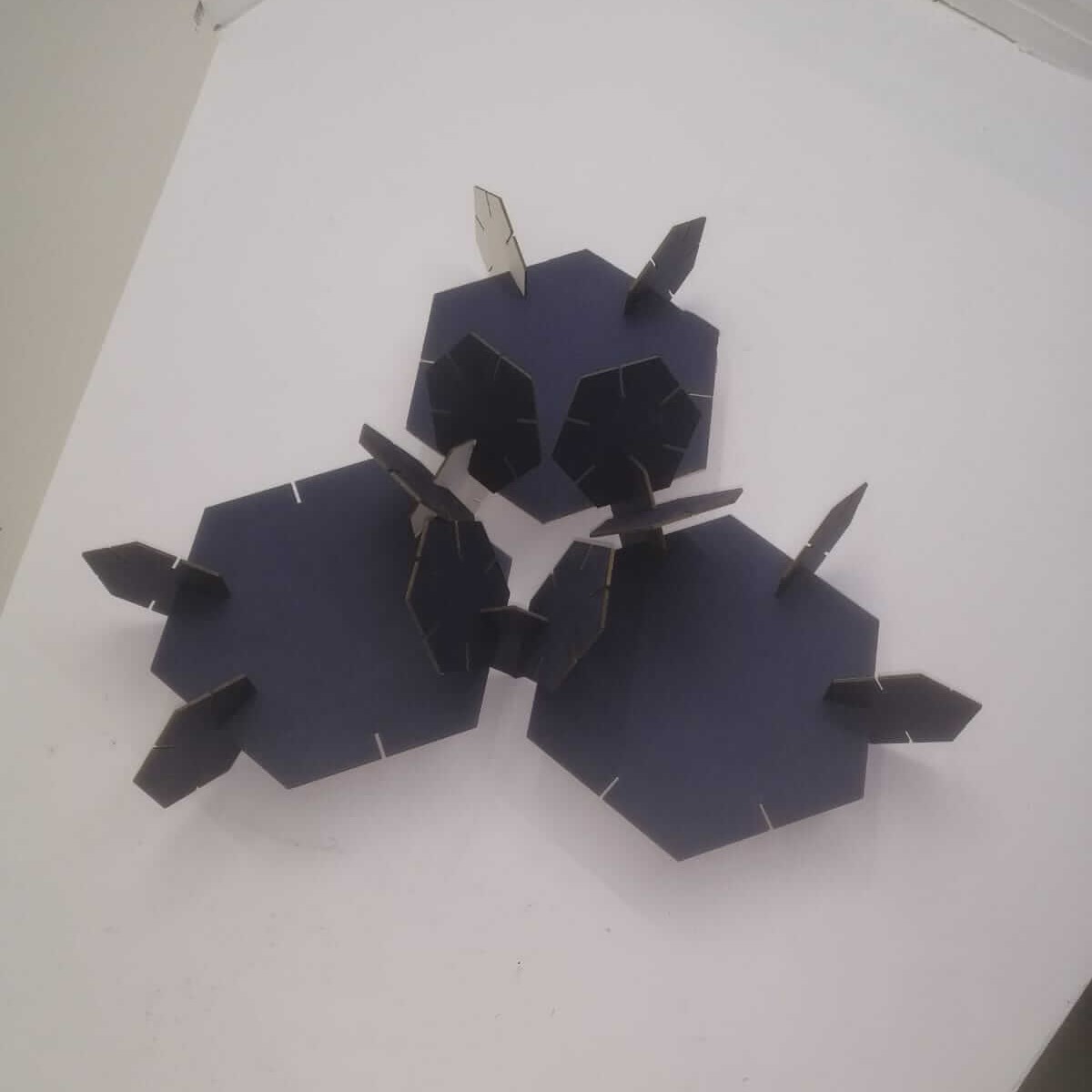
I combined my design with my friend’s design, you can see his documentation on his website.