6. Large format CNC (computer controlled Machining)
This week I worked on computer controlled Machining (CNC) and I designed my own shelves using Fusion 360.
The CNC machine can cut wood and up to aluminum. It can’t cut other metals because it is made of aluminum which is not strong enough to cut the other metals.
While using the machine we need to keep in our mind some safety points, for example:
- Always keep some distance between you and the machine while it is working.
- Wear protective glasses.
- When something is wrong press the stop button immediately.
- If you are wearing long sleeves make sure to fold them.
The machine uses different types of tips with different sizes, we will use the 6mm tip.
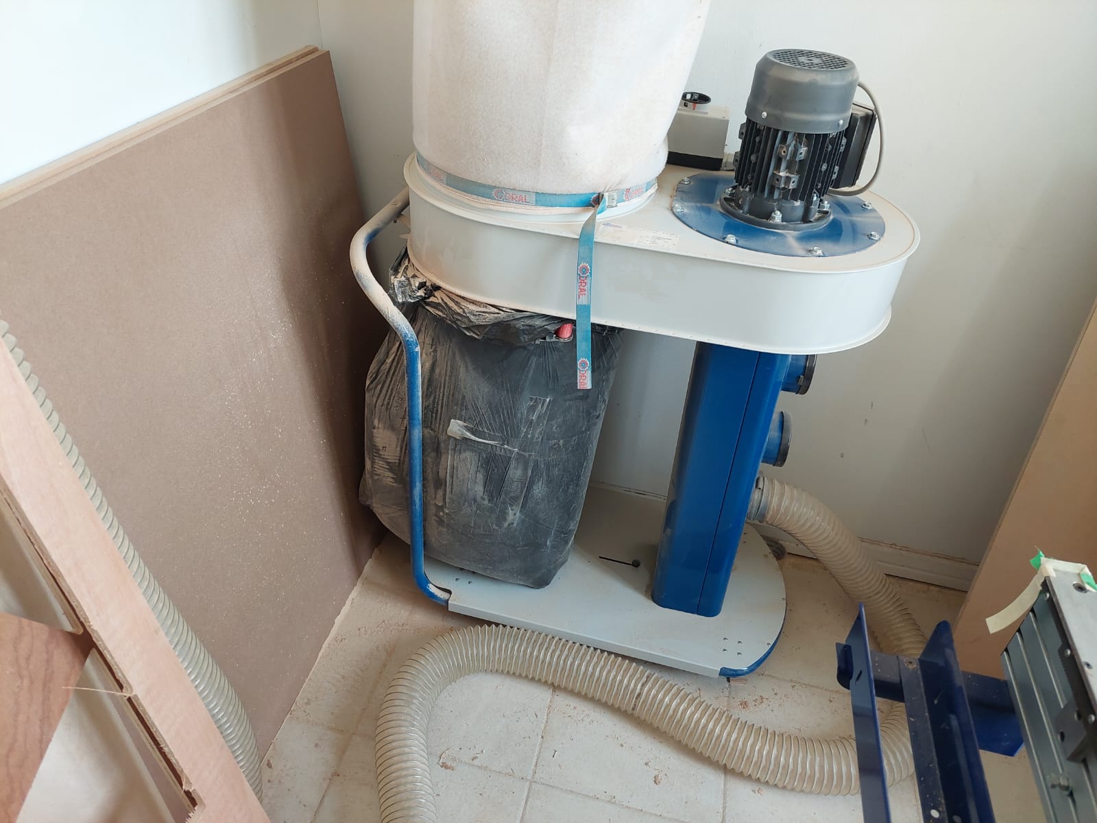
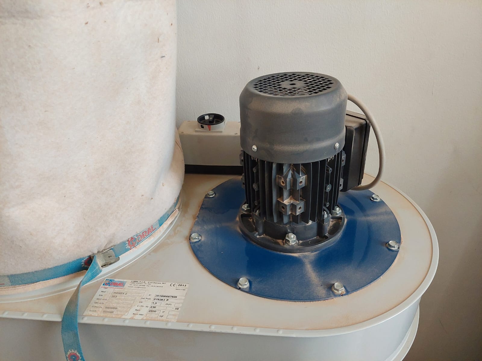
The wood waste is removed using a vacuum. We need to start the vacuum before start cutting.
This is the vacuum.
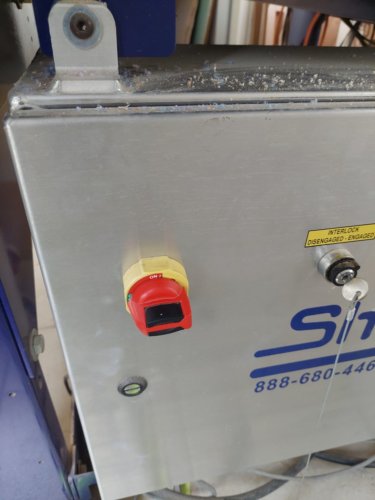
To turn on the machine we need to rotate (turn) the red key.
These are important buttons.
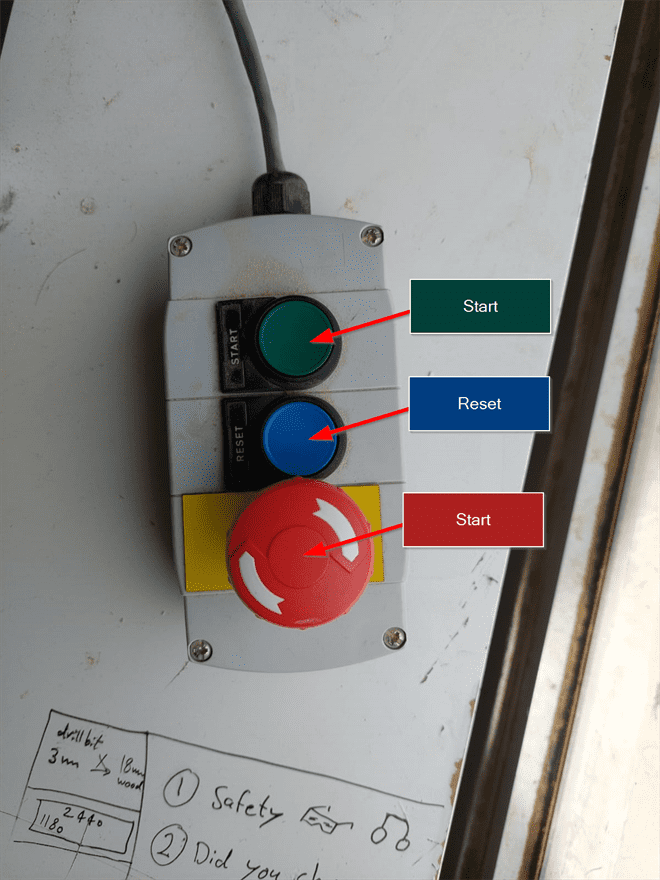
First, we need to press the reset button until we hear a click (crash) sound.
Then, we need to hold the start button for a few seconds to start the spindle.
Finally, the red button is to stop the machine in case something went wrong during the cutting.
1.1 Group assignment
We did some tests like runout, alignment, speeds, feeds, and toolpaths for the machine. You can refer to my partner’s page for the details.
1.2 Individual project (Make something big)
I designed shelves based on a design that I saw in the CNC room in Fab Lab but I changed some small things. Our instructor Abdullah helped us when we needed a help in Fusion 360 and during sanding and assembling. Also, he asked us to look for 3 different designs and he will tell us which design to work on.
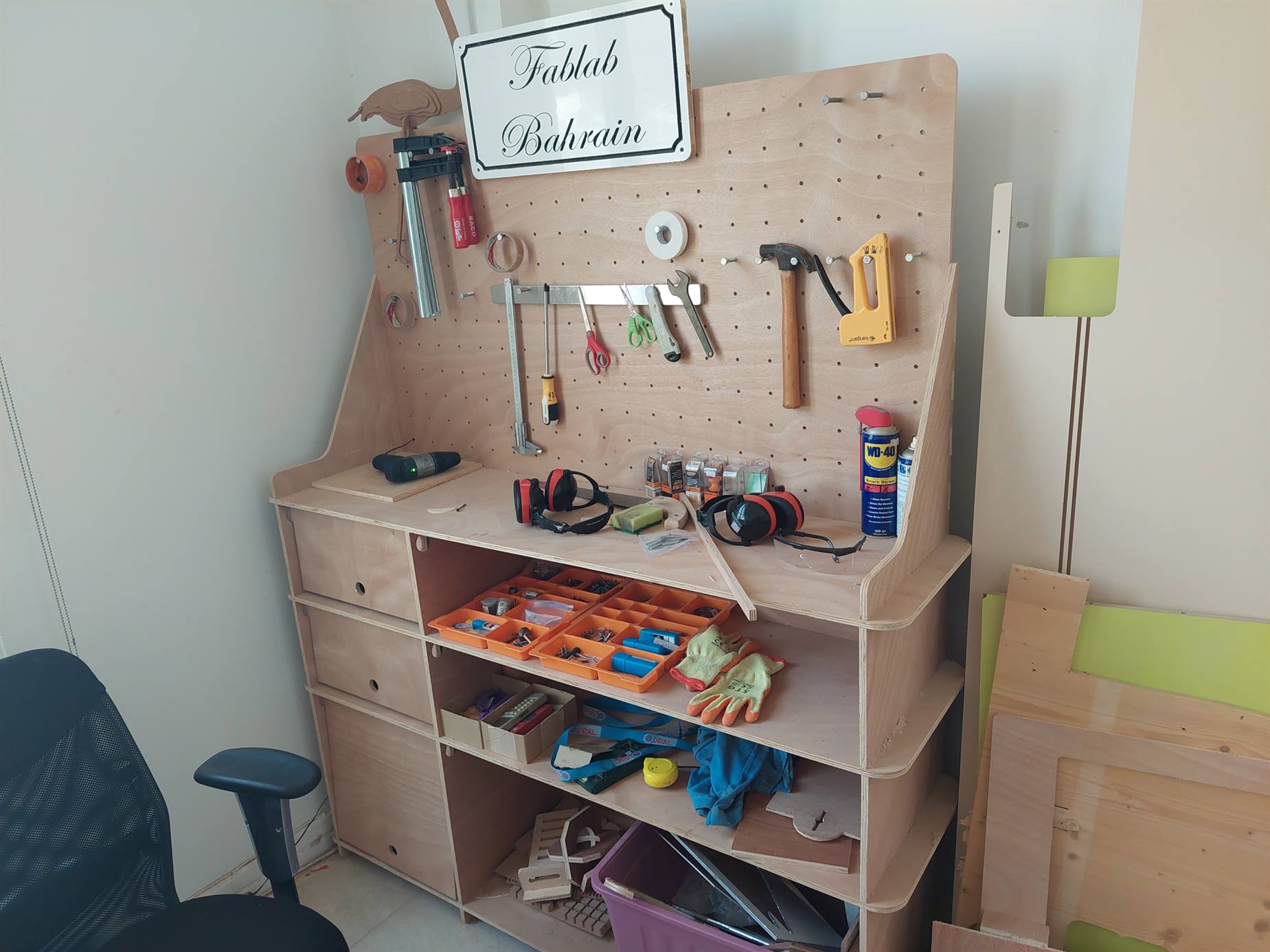
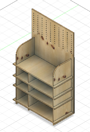
This is the original design that I used to design my own shelves.
1.2.1 Designing using Fusion 360.
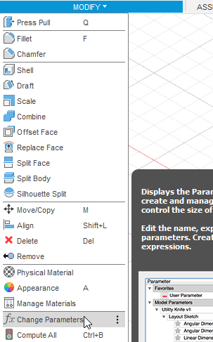
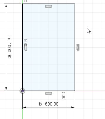
- As a start, I used the parametric design in case I needed to change the size of the objects after extruding.
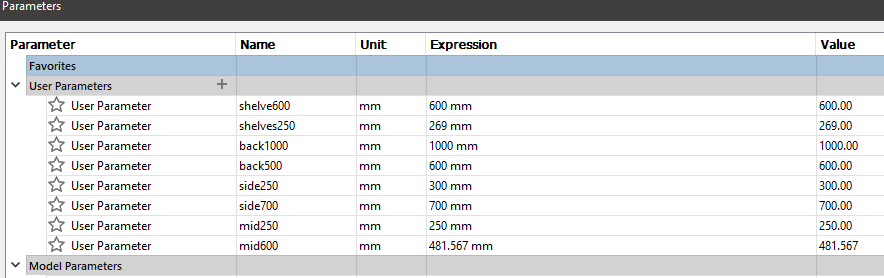
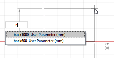
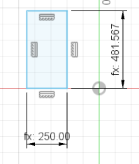
- I created a new sketch and then I drew a rectangle using the parametric design to set the dimensions. This represents the back side of the shelves.
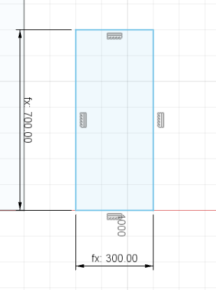
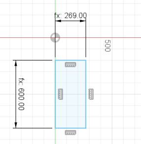
- Then, I drew another new sketch. This represents the right and left sides of the shelves.
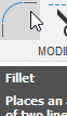
- I used the 'Fillet' tool to make a curve.
- I made a new sketch and I drew this rectangle that represents the middle part that separate the shelves into two sides.
- This new sketch contains a rectangle that represents the shelves.
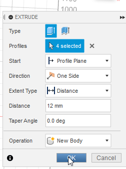
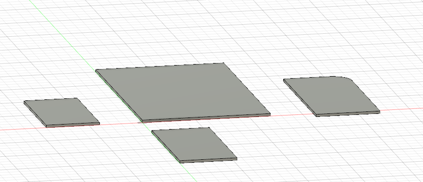
- I used extrude to convert the sketches to 3D objects.
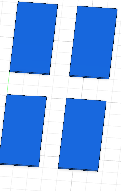
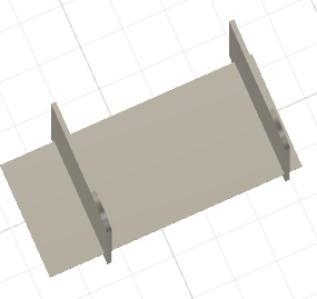
- I created copies of the side and the shelves to make the other side and the other shelves.
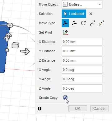
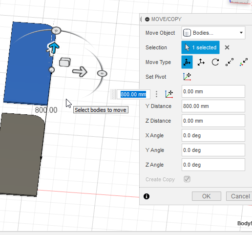
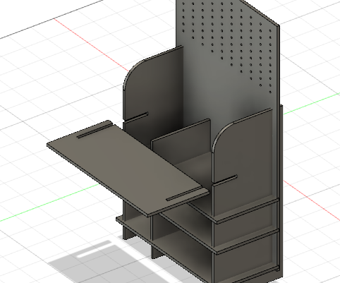
- I moved the 3D shapes to assemble the design.
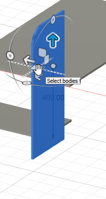
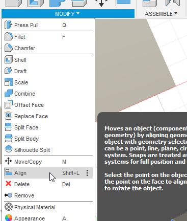
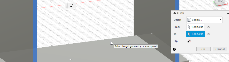
- The 'Align' tool helps a lot to assemble the design, it will align the selected object with another selected object.
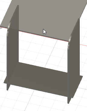
- I used the same steps to assemble the rest of the design.
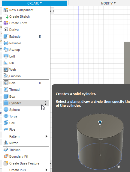
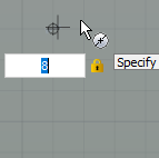
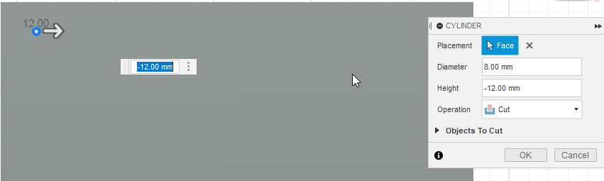
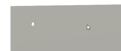
- To create the holes on the back side I drew a cylinder and cut it to make the hole.
- I chose the diameter to be 8mm.
- I chose the height as 12mm which is the same as the thickness of the wood and the 3D objects.
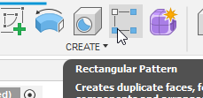
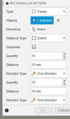
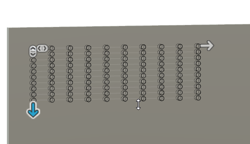
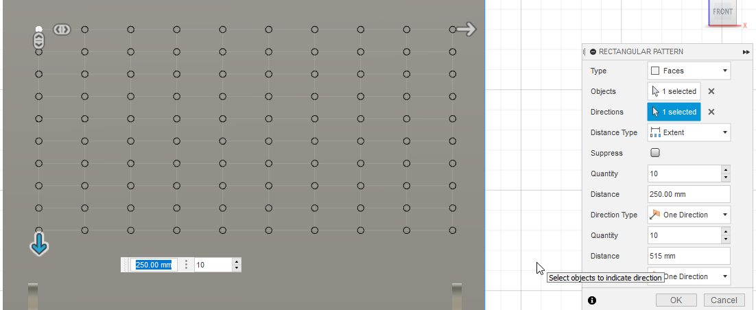
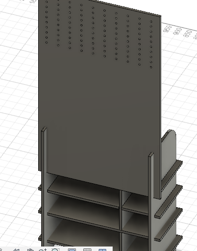
- To make the rest of the holes I used the 'rectangular pattern'. I created 10x10 holes as a total of 20 holes.
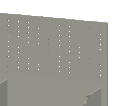
- These are the final look of the holes.
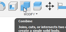
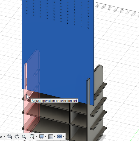
- To create the joints, I used the combine tool. I did not know how to create the joints at the beginning but Abdullah gave me an example and I did the rest.
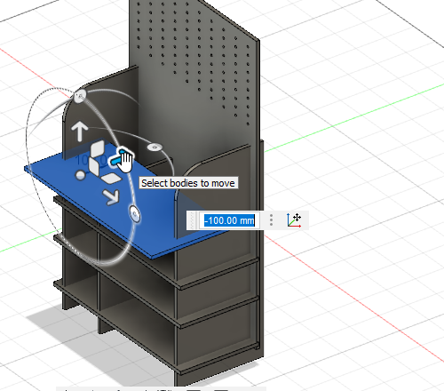
- First, I moved the shelve.
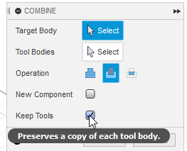
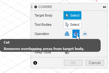
- Then, using the combine tool I ticked the 'Keep Tools' option and I changed the 'Operation' to 'cut'.
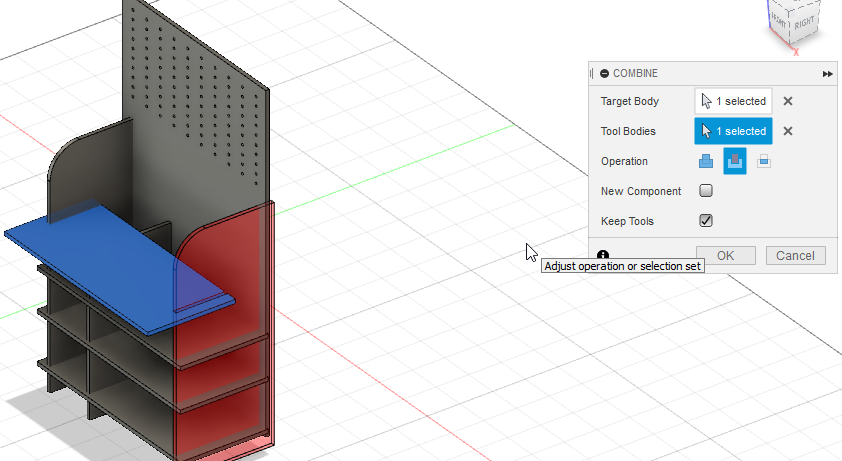
- I selected the shelve and then the left side and I clicked OK.
- Now I returned the shelve to its previous position and I selected the opposite, I chose the left side first then the shelve.
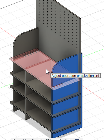
- And this is how the joint looked like.
- I did the same steps for the other shelves and the back side.
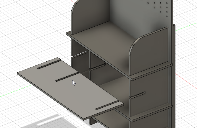
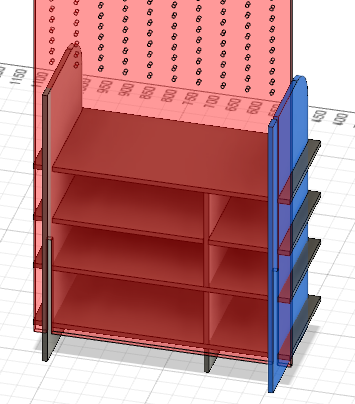
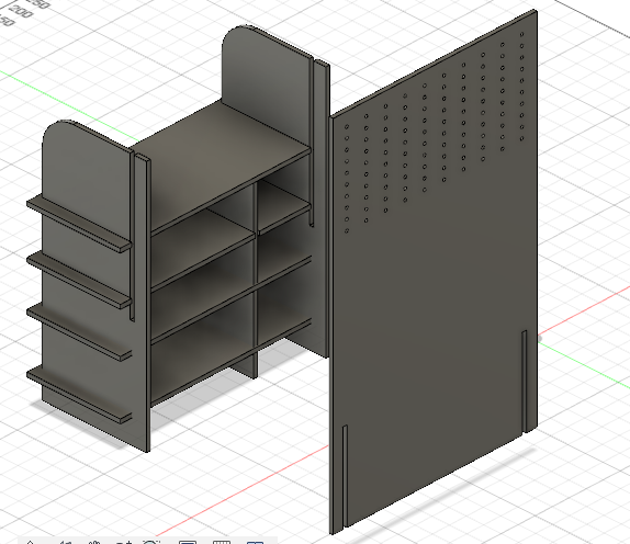
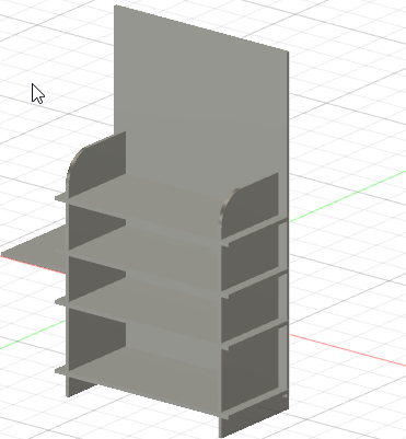
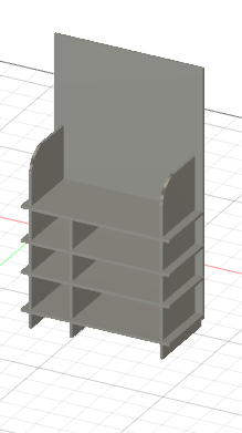
- This is the final design.
- I added an appearance for the design.
Note: I used the appearance just to show the final design and I removed it once I took the screenshot.
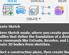
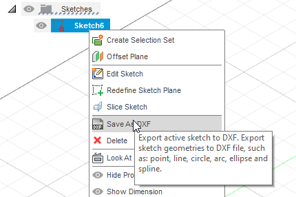
- To extract the design as DXF format, first I clicked on create sketch.
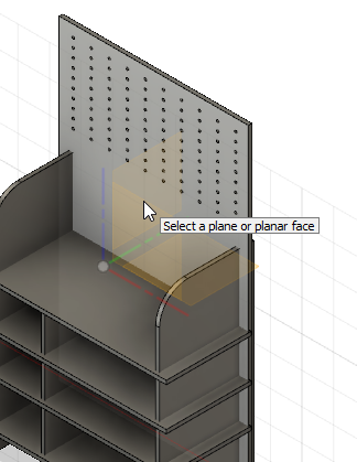
- I clicked on one of the 3D objects.
- I clicked on finish sketch.
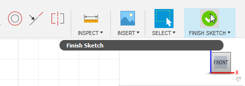
- A new sketch will appear in the left, I chose save as DXF and saved it. I did the same steps for the other 3D objects and I got a total of 8 DXF files.
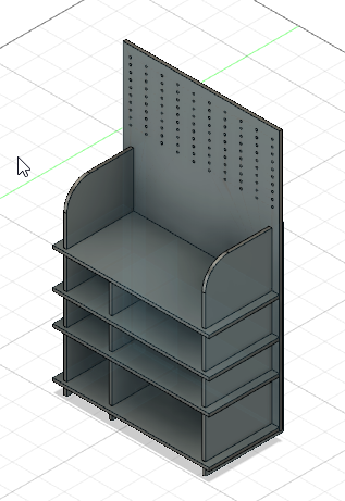
- This is a 3D model of my design.
Download Files
- DXF files (.dxf)
- F3D file (.f3d)
- STL file (.stl)
1.2.2 VCarve.
VCarve is a software for cutting parts on a CNC machine. It is used to add tabs, dog-bone fillet, and other useful features.
Tabs are uncut woods that will hold the cut wood from moving or flying away in case of small designs.
Dog-bone fillet is used to make the joint stable and make the pieces fit together.
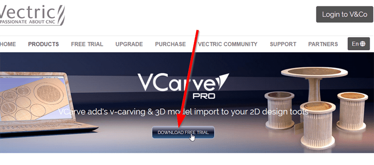
- I downloaded VCarve and installed it.
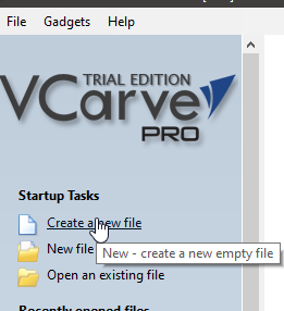
- I created a new file.
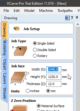
- I typed the dimensions of the wood that we will use.
- To prevent the machine from drilling throw the machine bed, we put a sheet that is called the sacrifice sheet, when the machine is working, the sacrifice sheet will be drilled instead of the machine bed. To install our wood on the sacrifice sheet and hold it we use screws, and to make sure that the machine does not hit the screws we leave a small distance (borders) using VCarve.
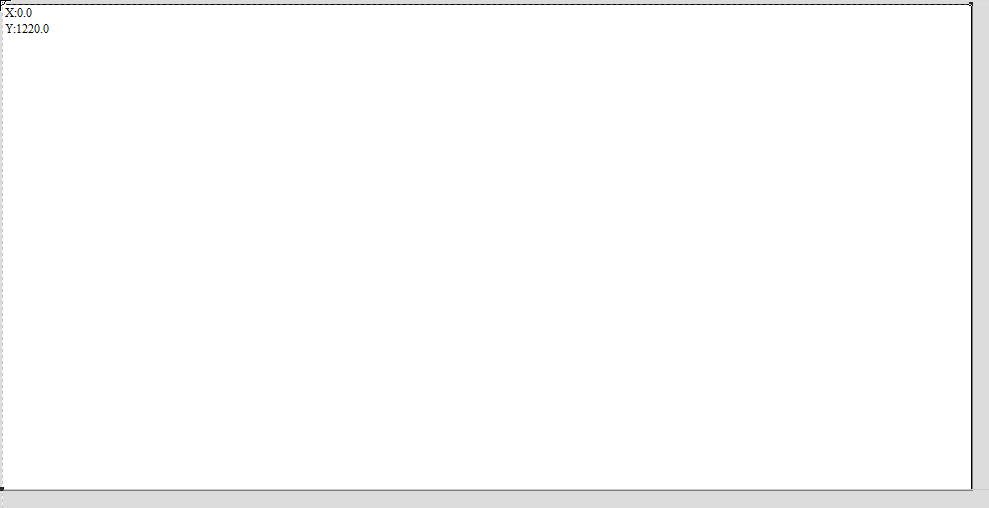
- Select the sheet from top left to botttom right.
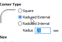
- Choose Radiused external and change radius to 25mm.
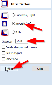
- Choose Offset.
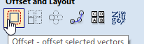
- Choose Inward/left and make sure the distance is 25mm.
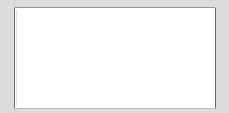
- This is how it should looks.
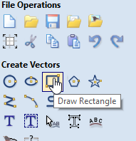
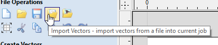
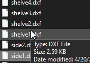
- Select import vectors and choose each DXF file one by one.
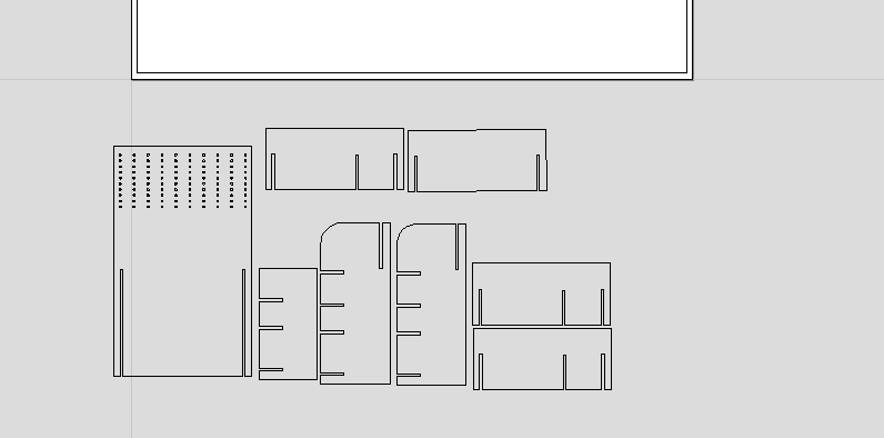
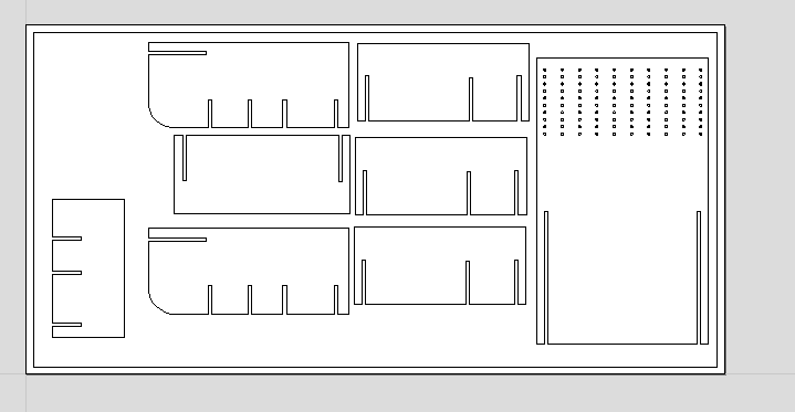
- Arrange the pieces.
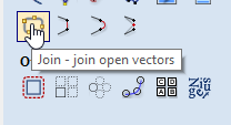
- Select join.
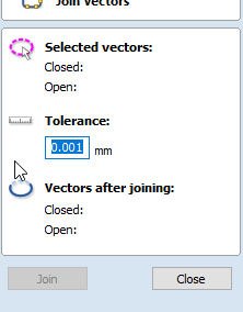
- Change Tolerance to 0.001mm.
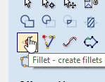
- Choose Fillet.
- Change Fillet/Tool Radius to 3.2mm and select Dog-Bone Fillet.
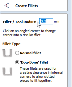
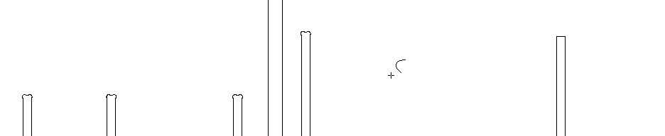
- Add the Dog-Bone Fillet.
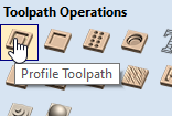
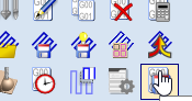
- Select the ToolPath from top right.
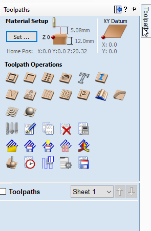
- Choose profile toolpath.
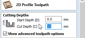
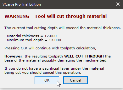
- Change the start depth to 0.0mm and the cut depth to 13mm.
- Click on edit passes.
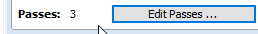
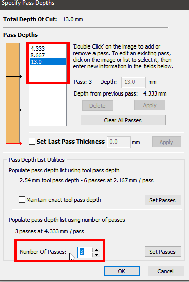
- Remove the Pass depths and keep these values as shown in the picture below. Change number of passes to 3.
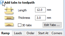
- Check add tabs to toolpath an dthen click on edit tabs.
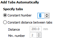
- change the constant number to 3.
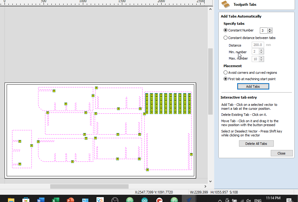
- Select first tab at machining start point and click on add tabs.
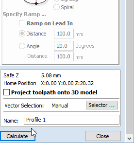
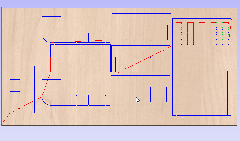
- Click on calculate.
- Click OK.
- Make sure everything is ok before cutting such as every piece is selected and the cutting path is correct.
- Save the file and send it to the machine to start cutting.
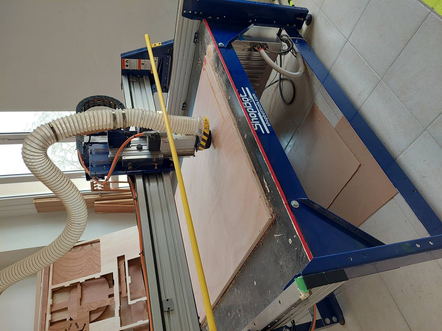
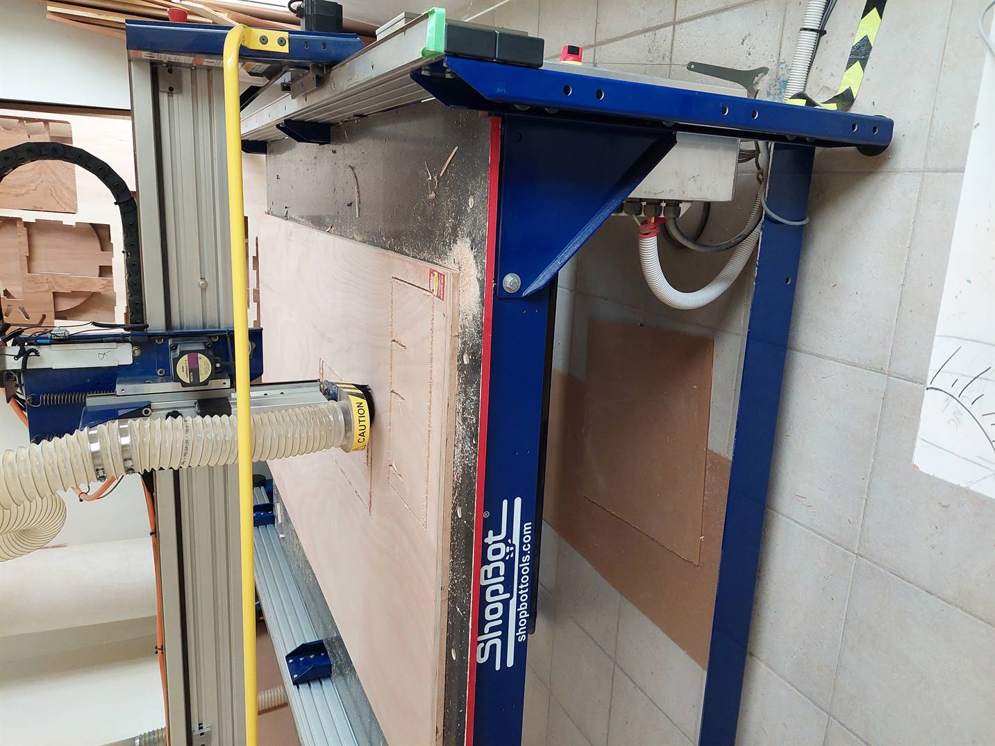
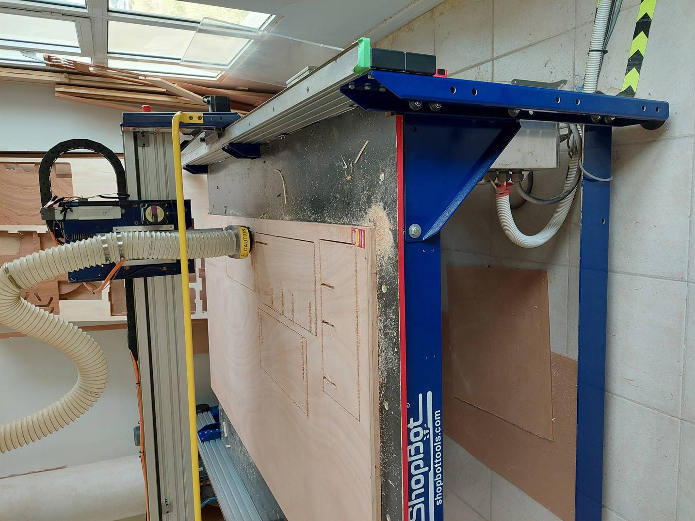
1.2.3 Cutting.
I set in front of the PC while cutting just in case something went wrong then I can push the button immediately to stop the machine.
- This is the cutting process.
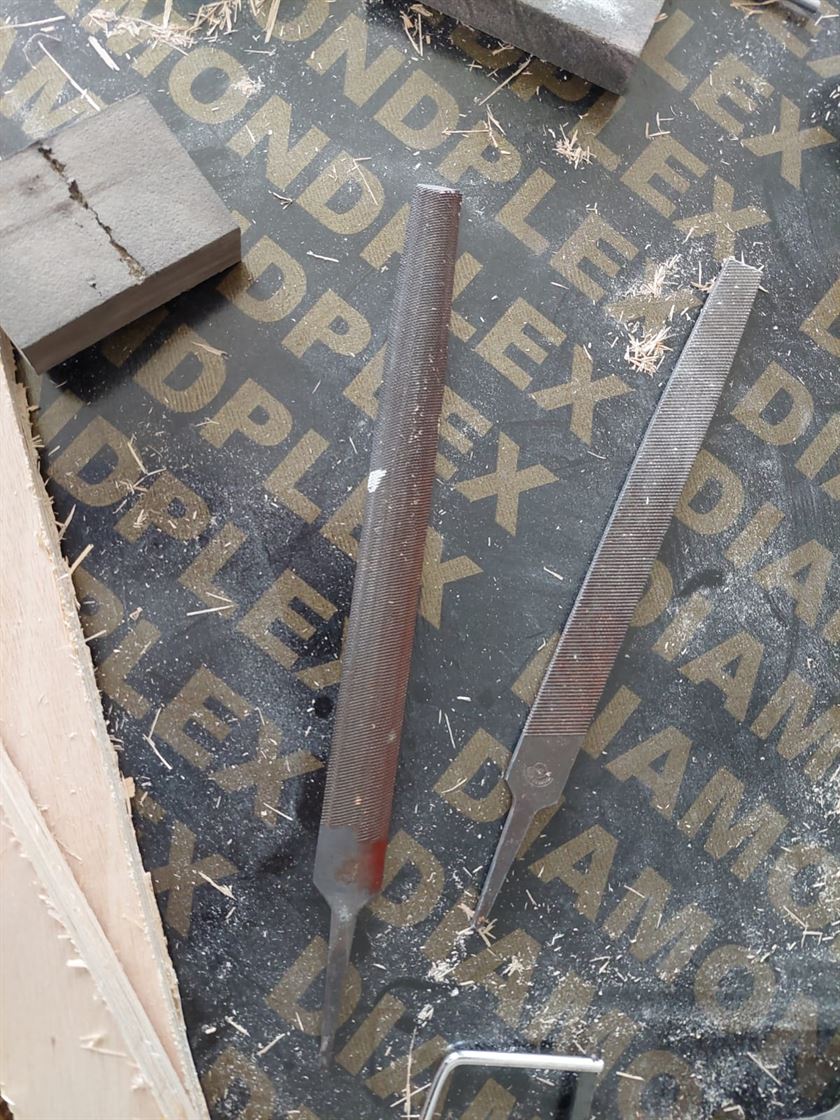
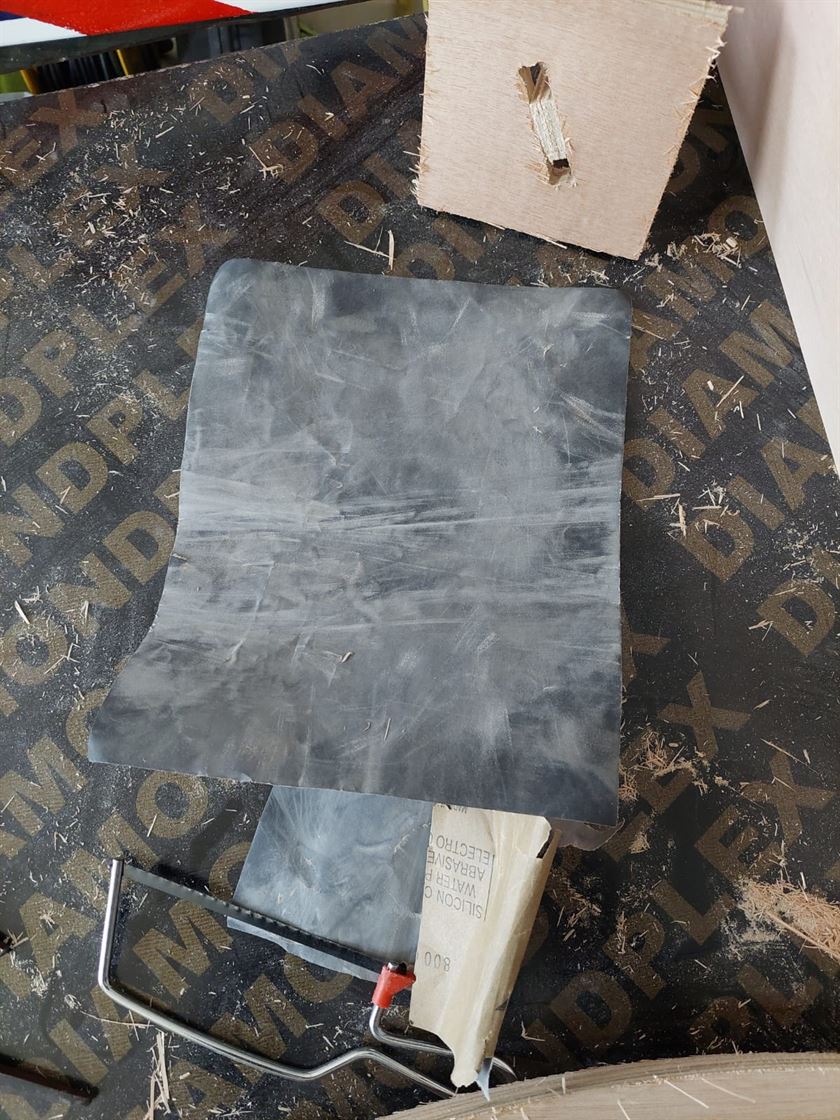
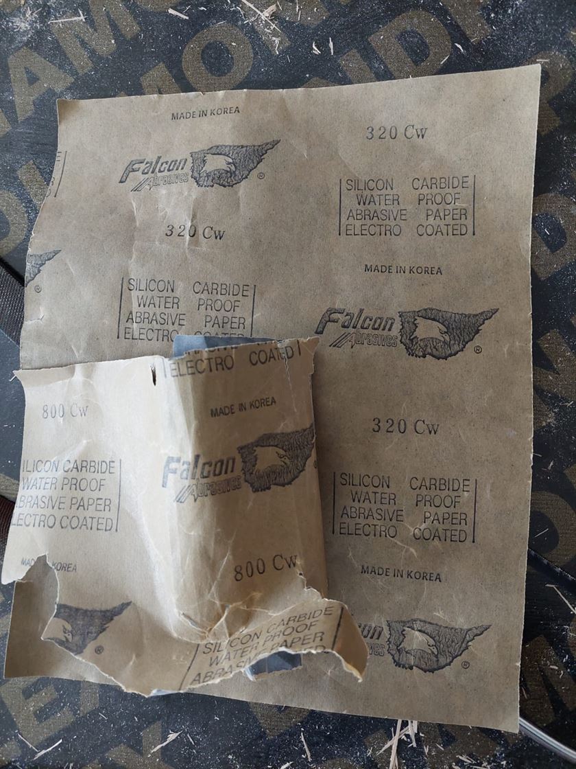
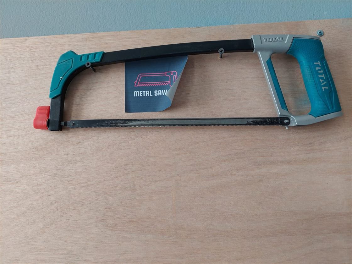
- After cutting, one of the staff 'Mohammed' removed the cut wood for me and I used the sanding papers with sizes 320 and 800 to remove the unwanted small woods and make the wood smoother. I used a file tool too and I also used a saw to remove some parts which cannot be removed using the file tool.
- This is the file tool.
- These are the sanding papers.
- This is the used saw.
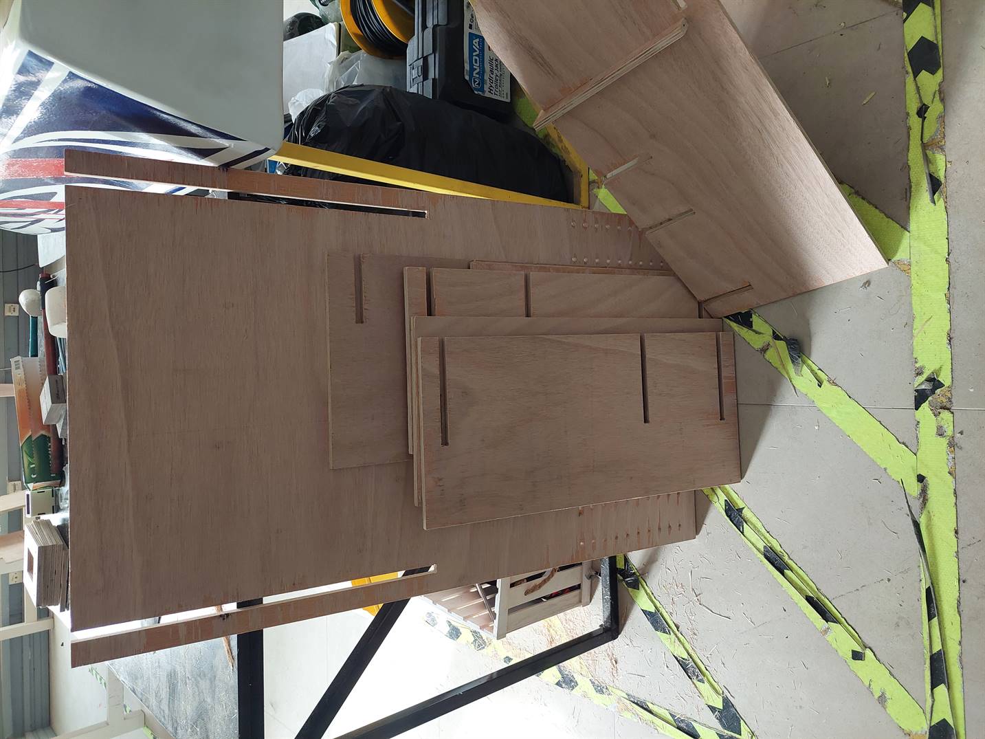
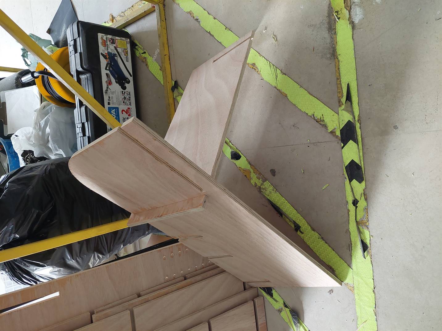
- These are the wood pieces after sanding.
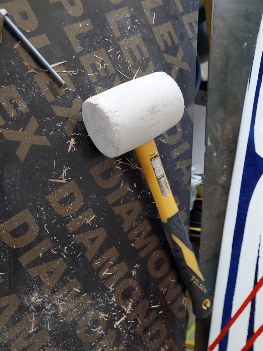
- To test the joints I tried to connect two parts together which was not bad. I used a hammer to assemble them.
- This is the used hammer.
- This is the tested joint.
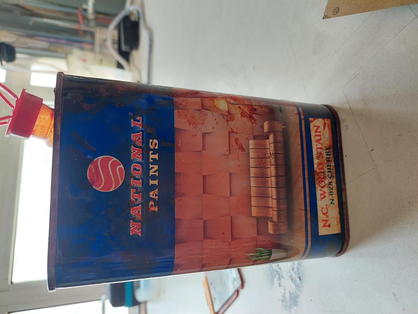
- I used a wood stain to paint the wood before assembling. I used the cherry color. My partner Iftikhar helped me to paint the wood.
- This is the stain.
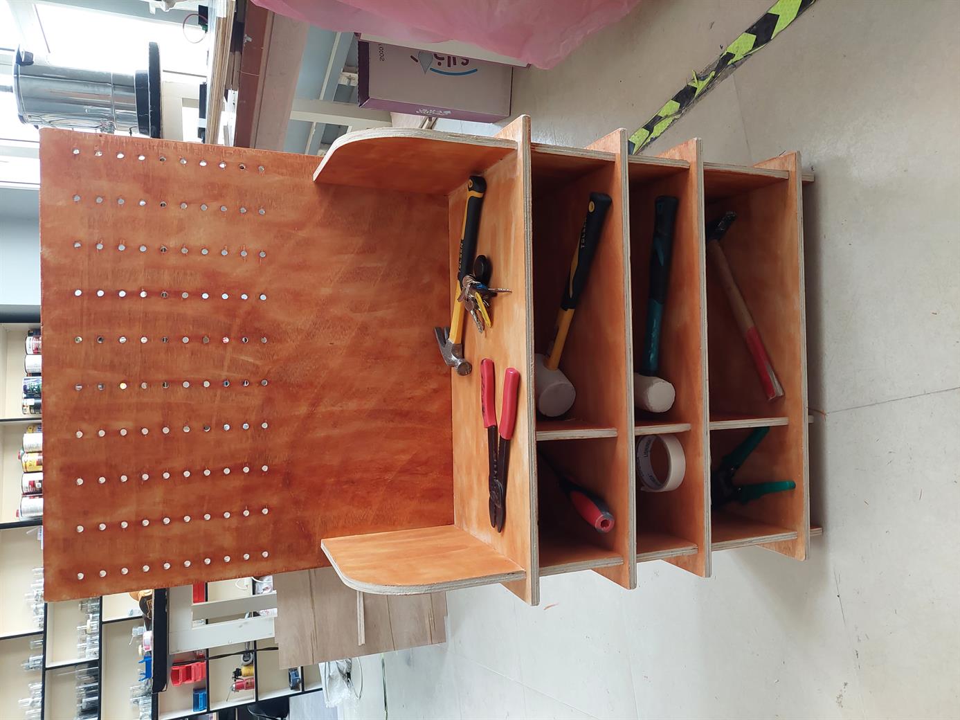
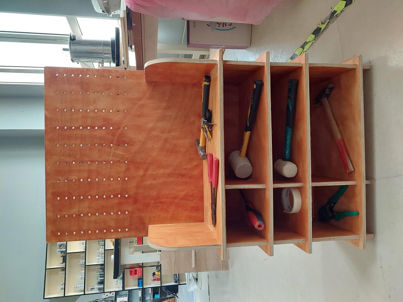
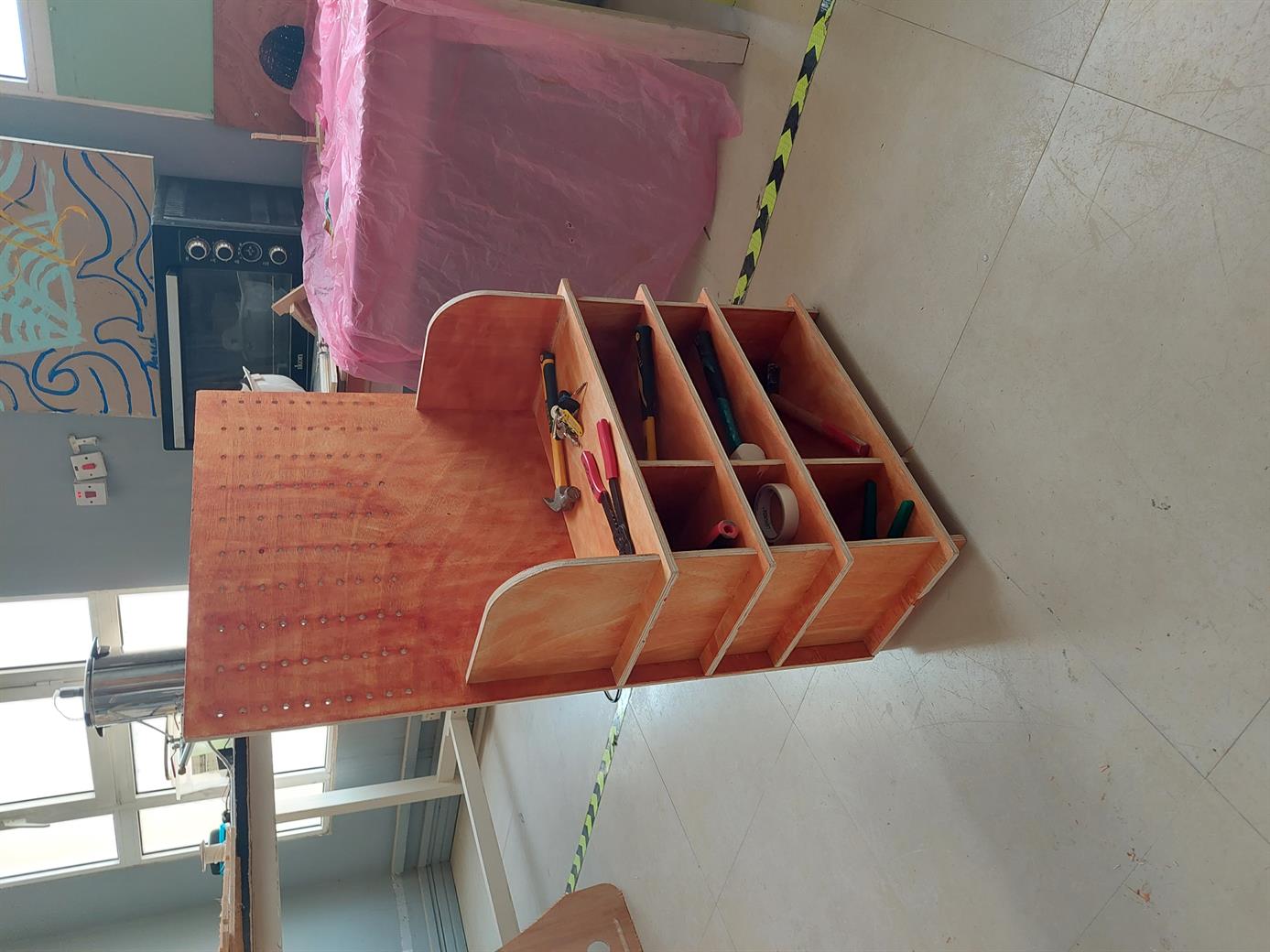
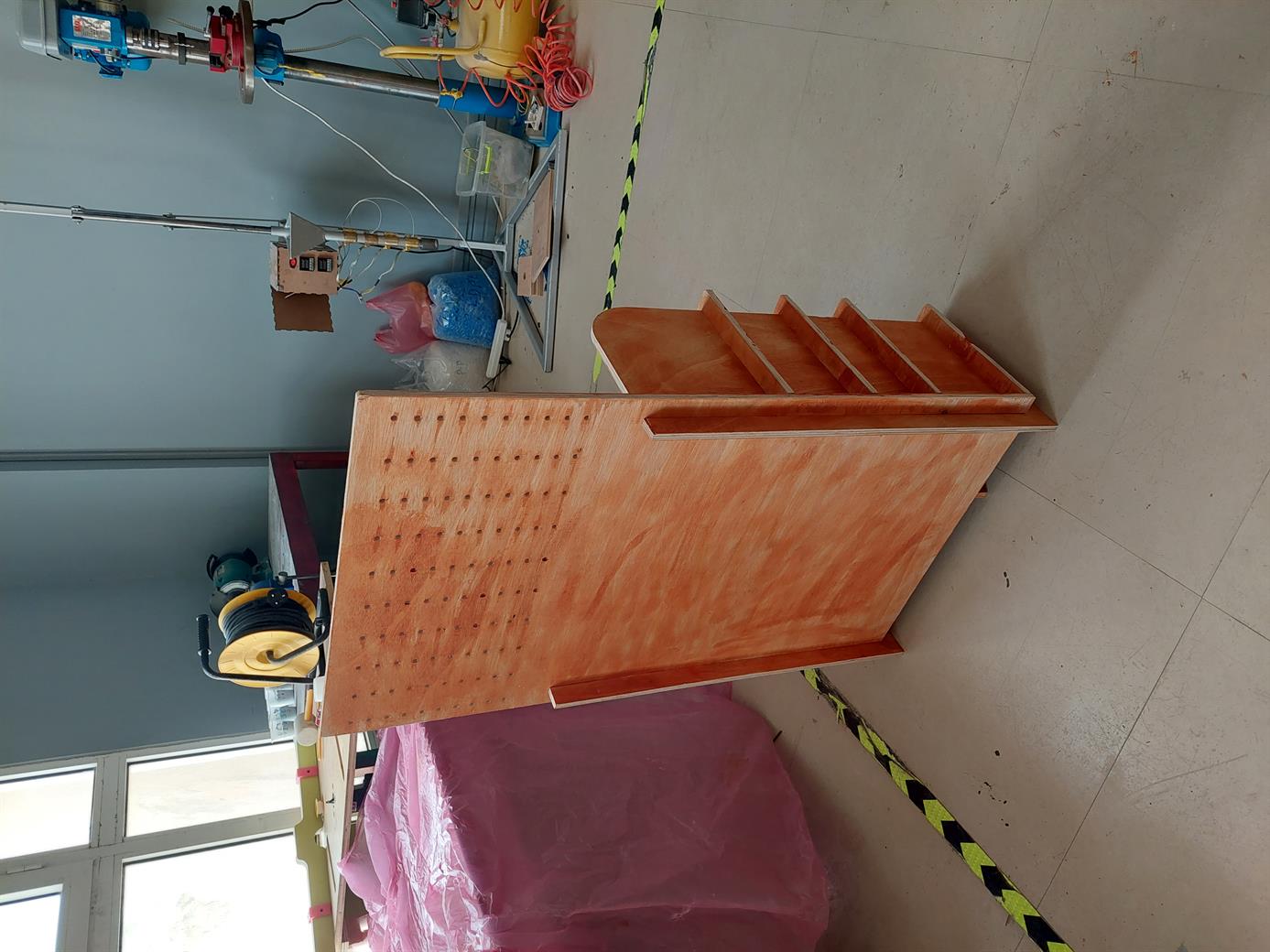
- The final result. My partners Mahmood and Iftikhar helped me to assemble it.