4. Embedded programming
This week I worked on embedded programming.
1. Group assignment
1.1 Group 1
We searched for different types of microcontrollers boards and we compared between them.
Refer to my colleague’s page to see the research.
1.2 Group 2
We also searched for different programming languages, and we compared between them and how many of them we can you use to program the same microcontrollers.
Refer to my colleague’s page to see the research.
2. Individual assignment
- What is Microcontroller?
- A microcontroller (MCU for microcontroller unit) is a small computer on a single metal-oxide-semiconductor (MOS) integrated circuit (IC) chip. A microcontroller contains one or more processor cores along with memory and programmable input/output peripherals.
- What is IDE?
- Integrated development environment or IDE, is a software application that provides comprehensive facilities to computer programmers for software development. An IDE normally consists of at least a source code editor, build automation tools and a debugger.
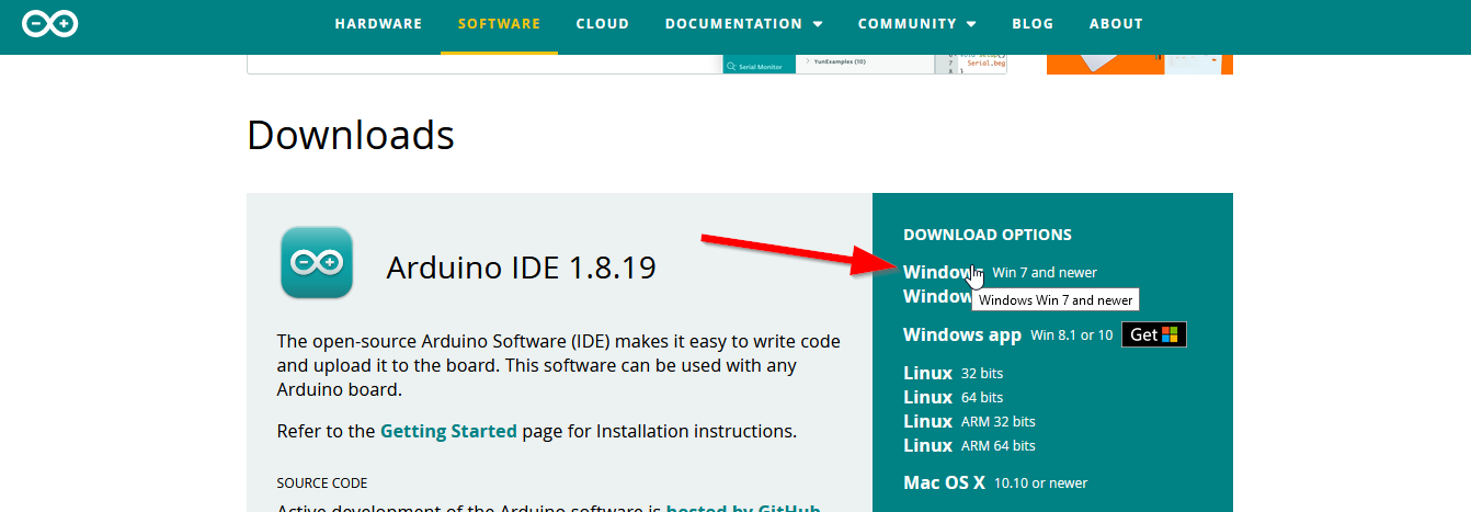
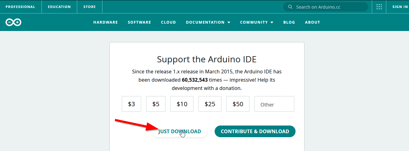
2.1 Arduino IDE.
- I downloaded and installed it.
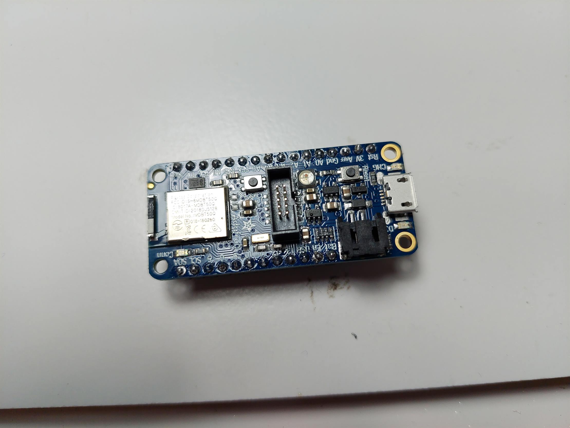
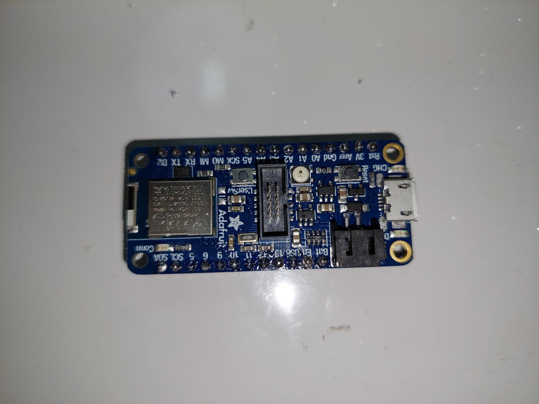
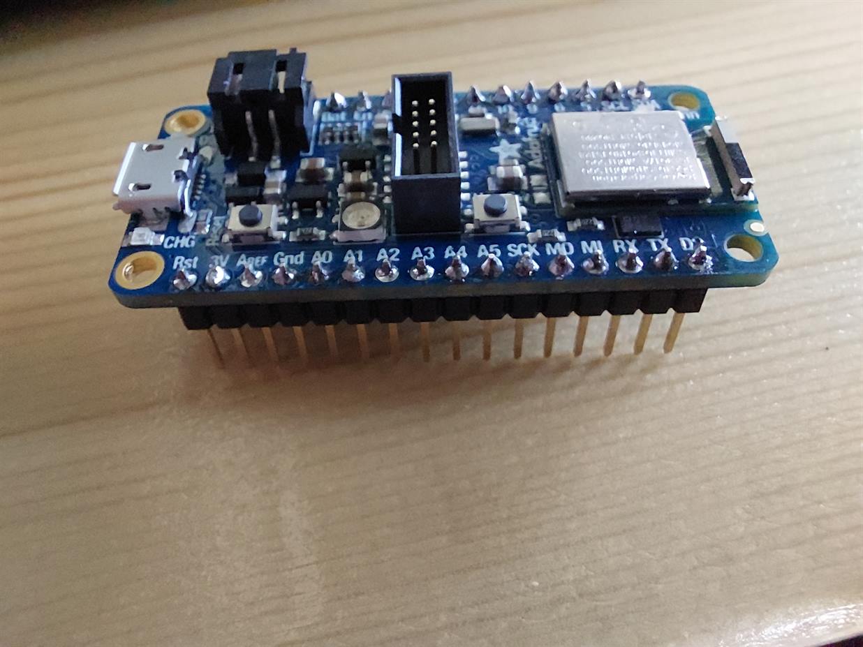
- The microcontroller that I used is Adafruit nRF52840 Feather. I went to Adafruit website and copied the needed link for my microcontroller.
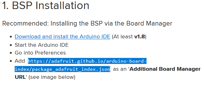
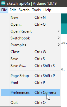
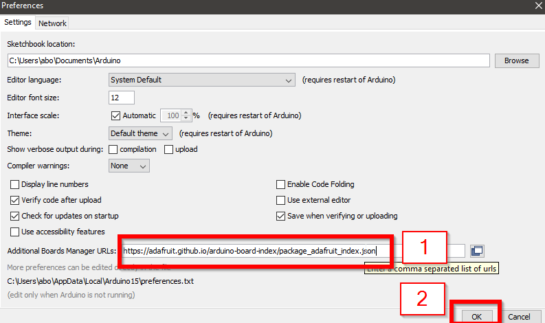
- I went to Adruino IDE and I opened the preferences. I pasted the link in Additional Boards Manager URLs.
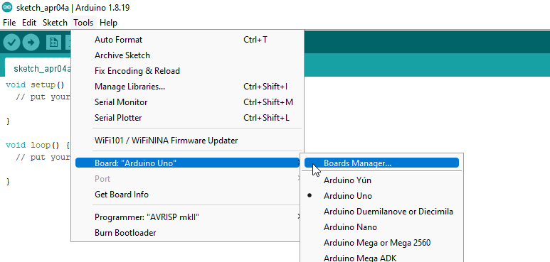
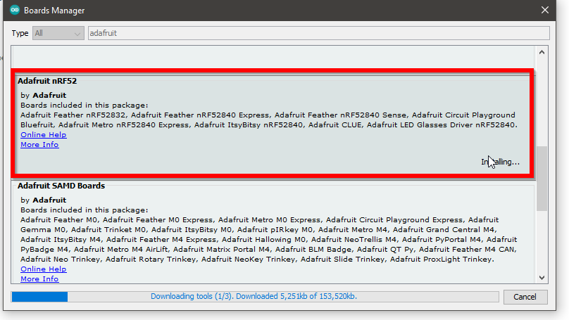
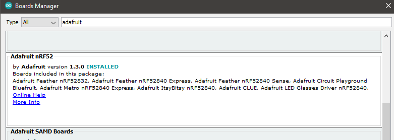
- I opened the Board Manager and I searched for adafruit nRF52. I installed it.
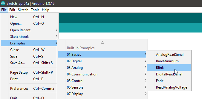
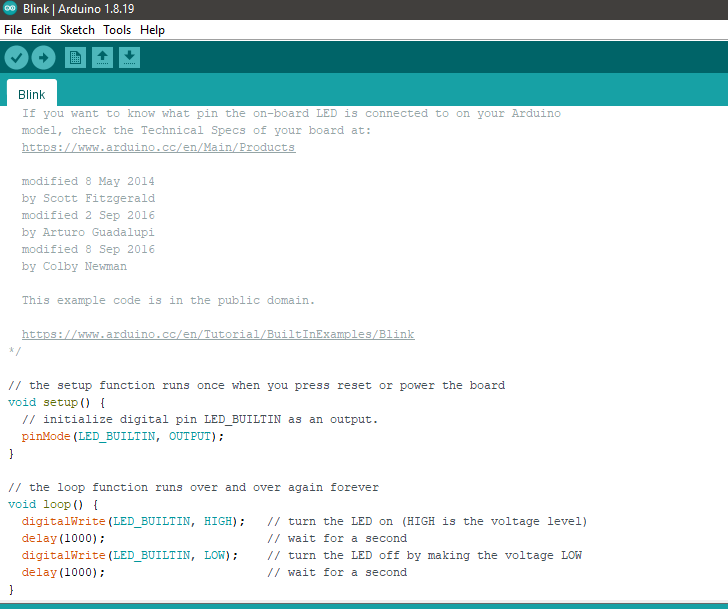
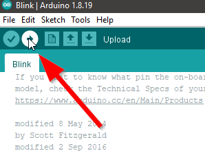
- I opened Blink example.
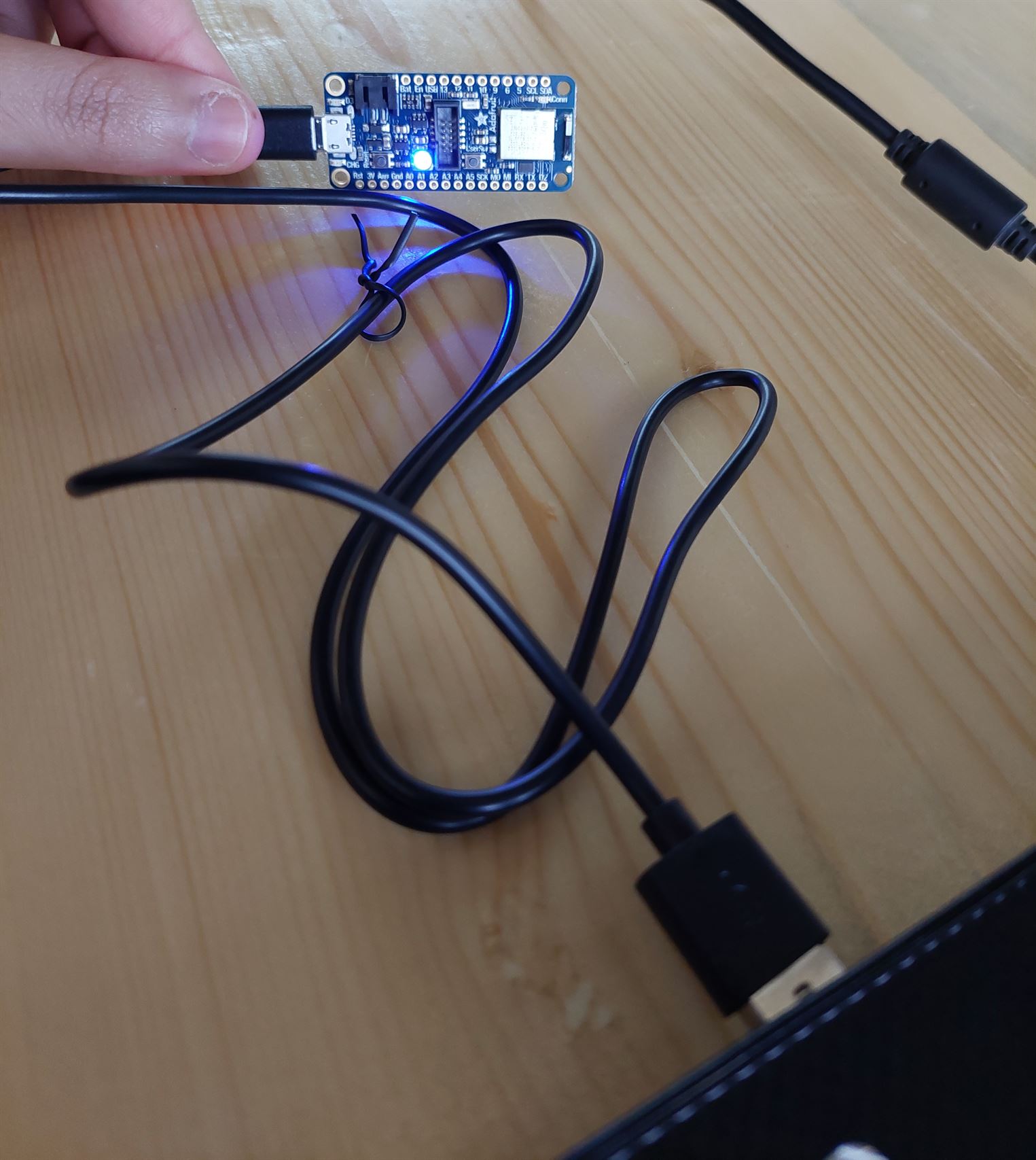
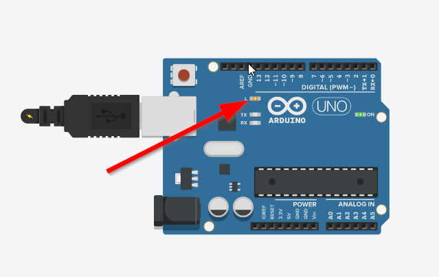
- I connected my Adafruit microcontroller to my PC via USB.
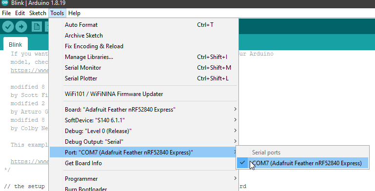
- I chose the port that the microcontroller is connected with.
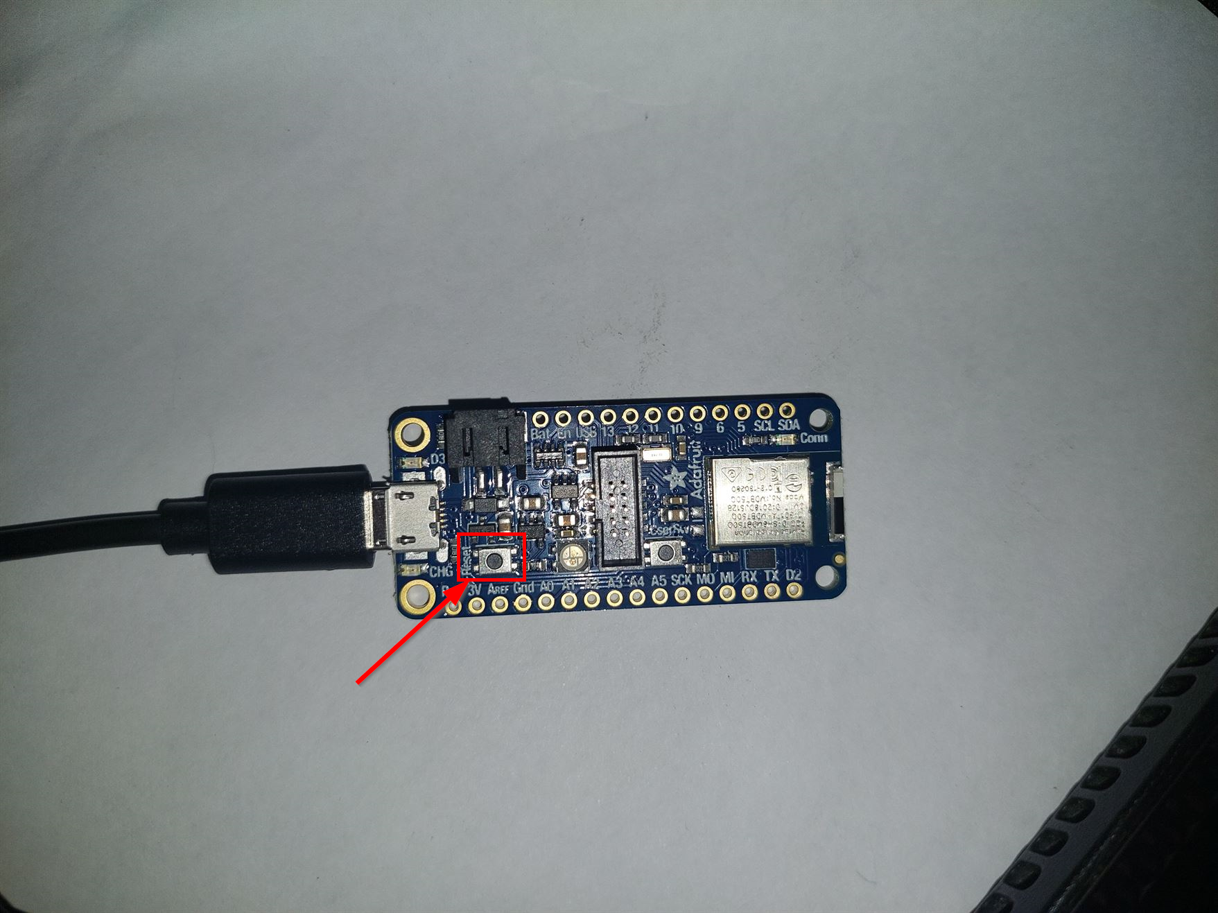
- If the port option is not selectable I just double click the button near the USB port on the microcontroller.
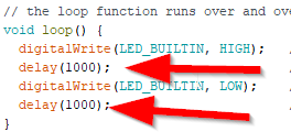
- The 1000 shown in the picture is the time in milliseconds. Also, HIGH means the LED will be on and LOW means the LED will be off.
- This is the code for the Blink example.
/*
  Blink

  Turns an LED on for one second, then off for one second, repeatedly.

  Most Arduinos have an on-board LED you can control. On the UNO, MEGA and ZERO
  it is attached to digital pin 13, on MKR1000 on pin 6. LED_BUILTIN is set to
  the correct LED pin independent of which board is used.
  If you want to know what pin the on-board LED is connected to on your Arduino
  model, check the Technical Specs of your board at:
  https://www.arduino.cc/en/Main/Products

  modified 8 May 2014
  by Scott Fitzgerald
  modified 2 Sep 2016
  by Arturo Guadalupi
  modified 8 Sep 2016
  by Colby Newman

  This example code is in the public domain.

  https://www.arduino.cc/en/Tutorial/BuiltInExamples/Blink
*/

// the setup function runs once when you press reset or power the board
void setup() {
  // initialize digital pin LED_BUILTIN as an output.
  pinMode(LED_BUILTIN, OUTPUT);
}

// the loop function runs over and over again forever
void loop() {
  digitalWrite(LED_BUILTIN, HIGH);   // turn the LED on (HIGH is the voltage level)
  delay(1000);                       // wait for a second
  digitalWrite(LED_BUILTIN, LOW);    // turn the LED off by making the voltage LOW
  delay(1000);                       // wait for a second
}
- I uploaded the code to the microcontroller.
- This is the result. The LED turn on for 1 second and then turn off and wait for 1 second before turning on again.
- I changed the time of the turning on (HIGH) to 300ms and the time for turning off (LOW) to 700ms.
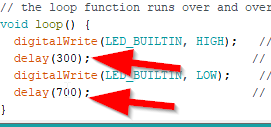
- This is the code
/*
  Blink

  Turns an LED on for one second, then off for one second, repeatedly.

  Most Arduinos have an on-board LED you can control. On the UNO, MEGA and ZERO
  it is attached to digital pin 13, on MKR1000 on pin 6. LED_BUILTIN is set to
  the correct LED pin independent of which board is used.
  If you want to know what pin the on-board LED is connected to on your Arduino
  model, check the Technical Specs of your board at:
  https://www.arduino.cc/en/Main/Products

  modified 8 May 2014
  by Scott Fitzgerald
  modified 2 Sep 2016
  by Arturo Guadalupi
  modified 8 Sep 2016
  by Colby Newman

  This example code is in the public domain.

  https://www.arduino.cc/en/Tutorial/BuiltInExamples/Blink
*/

// the setup function runs once when you press reset or power the board
void setup() {
  // initialize digital pin LED_BUILTIN as an output.
  pinMode(LED_BUILTIN, OUTPUT);
}

// the loop function runs over and over again forever
void loop() {
  digitalWrite(LED_BUILTIN, HIGH);   // turn the LED on (HIGH is the voltage level)
  delay(300);                       // wait for a second
  digitalWrite(LED_BUILTIN, LOW);    // turn the LED off by making the voltage LOW
  delay(700);                       // wait for a second
}
- If the upload failed I simply double click the button on the microcontroller to reset it, and I made sure to choose the correct port.
- This is the result. The LED turns on for 300ms and then turns off for 700ms.
- I changed the time of the turning on (HIGH) to 700ms and the time for turning off (LOW) to 300ms and I uploaded the code.
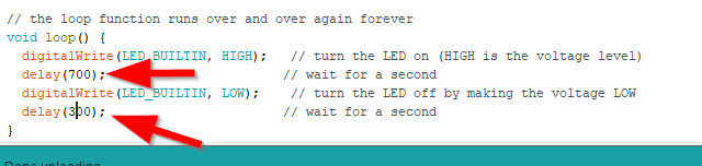
- This is the code
/*
  Blink

  Turns an LED on for one second, then off for one second, repeatedly.

  Most Arduinos have an on-board LED you can control. On the UNO, MEGA and ZERO
  it is attached to digital pin 13, on MKR1000 on pin 6. LED_BUILTIN is set to
  the correct LED pin independent of which board is used.
  If you want to know what pin the on-board LED is connected to on your Arduino
  model, check the Technical Specs of your board at:
  https://www.arduino.cc/en/Main/Products

  modified 8 May 2014
  by Scott Fitzgerald
  modified 2 Sep 2016
  by Arturo Guadalupi
  modified 8 Sep 2016
  by Colby Newman

  This example code is in the public domain.

  https://www.arduino.cc/en/Tutorial/BuiltInExamples/Blink
*/

// the setup function runs once when you press reset or power the board
void setup() {
  // initialize digital pin LED_BUILTIN as an output.
  pinMode(LED_BUILTIN, OUTPUT);
}

// the loop function runs over and over again forever
void loop() {
  digitalWrite(LED_BUILTIN, HIGH);   // turn the LED on (HIGH is the voltage level)
  delay(700);                       // wait for a second
  digitalWrite(LED_BUILTIN, LOW);    // turn the LED off by making the voltage LOW
  delay(300);                       // wait for a second
}
- This is the result. The LED turns on for 700ms and then turns off for 300ms.
- We used a website called Morse Code Translator to translate a word to a Morse code. I translated the word "Null" and then I edited the code to make the LED blinks as a Morse code.
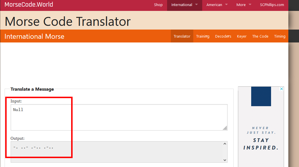
- The dot '.' Means turn on for 1 second.
- The Underscore '_' Means turn on for 2 seconds.
- The space in the same letter means turn off for 0.5 seconds.
- The space between two letter means turn off for 2 seconds.
- At the end of the code I added a turning off code for 4 seconds to know that the Morse code finished and it will start blinking again after the 4 seconds.
- This is the code.
/*
  Blink

  Turns an LED on for one second, then off for one second, repeatedly.

  Most Arduinos have an on-board LED you can control. On the UNO, MEGA and ZERO
  it is attached to digital pin 13, on MKR1000 on pin 6. LED_BUILTIN is set to
  the correct LED pin independent of which board is used.
  If you want to know what pin the on-board LED is connected to on your Arduino
  model, check the Technical Specs of your board at:
  https://www.arduino.cc/en/Main/Products

  modified 8 May 2014
  by Scott Fitzgerald
  modified 2 Sep 2016
  by Arturo Guadalupi
  modified 8 Sep 2016
  by Colby Newman

  This example code is in the public domain.

  https://www.arduino.cc/en/Tutorial/BuiltInExamples/Blink
*/

// the setup function runs once when you press reset or power the board
void setup() {
  // initialize digital pin LED_BUILTIN as an output.
  pinMode(LED_BUILTIN, OUTPUT);
}

// the loop function runs over and over again forever
void loop() {
  digitalWrite(LED_BUILTIN, HIGH);   // turn the LED on (HIGH is the voltage level)
  delay(2000);                       // wait for a second
  digitalWrite(LED_BUILTIN, LOW);    // turn the LED off by making the voltage LOW
  delay(500);                       // wait for a second
  digitalWrite(LED_BUILTIN, HIGH);
  delay(1000);
  digitalWrite(LED_BUILTIN, LOW);
  delay(2000);

  digitalWrite(LED_BUILTIN, HIGH);
  delay(1000);
  digitalWrite(LED_BUILTIN, LOW);
  delay(500);
  digitalWrite(LED_BUILTIN, HIGH);
  delay(1000);
  digitalWrite(LED_BUILTIN, LOW);
  delay(500);
  digitalWrite(LED_BUILTIN, HIGH);
  delay(2000);
  digitalWrite(LED_BUILTIN, LOW);
  delay(2000);

  digitalWrite(LED_BUILTIN, HIGH);
  delay(1000);
  digitalWrite(LED_BUILTIN, LOW);
  delay(500);
  digitalWrite(LED_BUILTIN, HIGH);
  delay(2000);
  digitalWrite(LED_BUILTIN, LOW);
  delay(500);
  digitalWrite(LED_BUILTIN, HIGH);
  delay(1000);
  digitalWrite(LED_BUILTIN, LOW);
  delay(500);
  digitalWrite(LED_BUILTIN, HIGH);
  delay(1000);
  digitalWrite(LED_BUILTIN, LOW);
  delay(2000);

  digitalWrite(LED_BUILTIN, HIGH);
  delay(1000);
  digitalWrite(LED_BUILTIN, LOW);
  delay(500);
  digitalWrite(LED_BUILTIN, HIGH);
  delay(2000);
  digitalWrite(LED_BUILTIN, LOW);
  delay(500);
  digitalWrite(LED_BUILTIN, HIGH);
  delay(1000);
  digitalWrite(LED_BUILTIN, LOW);
  delay(500);
  digitalWrite(LED_BUILTIN, HIGH);
  delay(1000);
  digitalWrite(LED_BUILTIN, LOW);
  delay(4000);

}
- This is the result.
2.2 Tinkercad
We used Tinkercad again in this week to make a circuit. Tinkercad has a code editor which supports blocks.
- What is block?
-
Block or code block or block of code is a lexical structure of source code which is grouped together. Blocks consist of one or more declarations and statements. A programming language that permits the creation of blocks, including blocks nested within other blocks, is called a block-structured programming language
These are the steps to use circuits in Tinkercad.
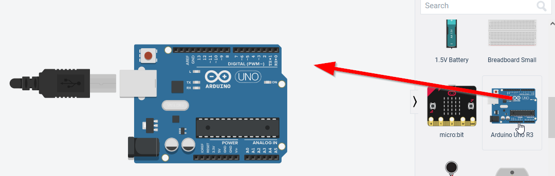
- I opened the circuit section and I created a new circuit.


- I dragged an Arduino Uno R3.
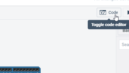
- I toggled the code editor.
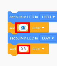
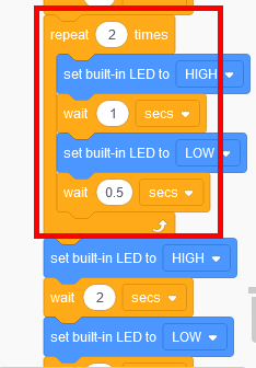
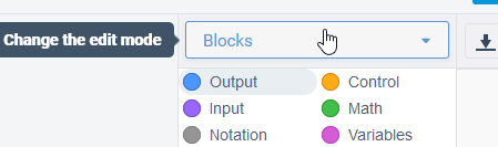
- These are the blocks. The orange blocks are called "Control", and the blue blocks are called "Output". I changed the timing of turning on and off the LED.
- I clicked on start simulation to see how the circuit will work.
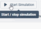
- The LED started blinking.
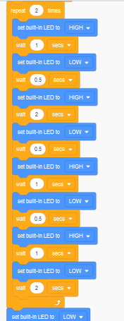
- I created blocks to simulate a Morse code of the word null just like what I did in Arduino IDE, but in Tinkercad, I used a "Control" block called repeat. It will repeat the same code n times. You can choose the number of times.
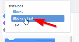
- We can also check the text code in Tinkercad, by changing the edit mode to blocks + text.
- The new code that represents the repeat "Control" block is "for". It is used to repeat the operations multiple times. This usually called loop in programming.
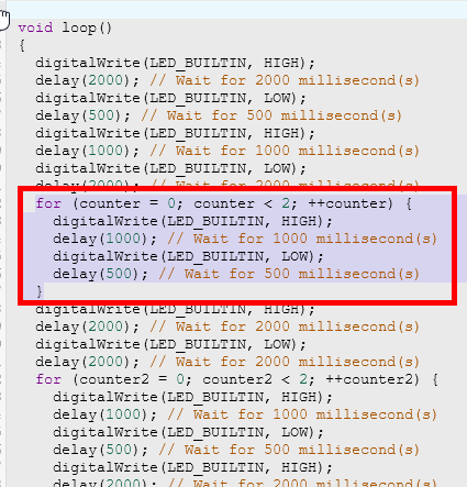
- This is the code with the "for loop".
// C++ code
//
int counter;

int counter2;

void setup()
{
  pinMode(LED_BUILTIN, OUTPUT);
}

void loop()
{
  digitalWrite(LED_BUILTIN, HIGH);
  delay(2000); // Wait for 2000 millisecond(s)
  digitalWrite(LED_BUILTIN, LOW);
  delay(500); // Wait for 500 millisecond(s)
  digitalWrite(LED_BUILTIN, HIGH);
  delay(1000); // Wait for 1000 millisecond(s)
  digitalWrite(LED_BUILTIN, LOW);
  delay(2000); // Wait for 2000 millisecond(s)
  for (counter = 0; counter < 2; ++counter) {
    digitalWrite(LED_BUILTIN, HIGH);
    delay(1000); // Wait for 1000 millisecond(s)
    digitalWrite(LED_BUILTIN, LOW);
    delay(500); // Wait for 500 millisecond(s)
  }
  digitalWrite(LED_BUILTIN, HIGH);
  delay(2000); // Wait for 2000 millisecond(s)
  digitalWrite(LED_BUILTIN, LOW);
  delay(2000); // Wait for 2000 millisecond(s)
  for (counter2 = 0; counter2 < 2; ++counter2) {
    digitalWrite(LED_BUILTIN, HIGH);
    delay(1000); // Wait for 1000 millisecond(s)
    digitalWrite(LED_BUILTIN, LOW);
    delay(500); // Wait for 500 millisecond(s)
    digitalWrite(LED_BUILTIN, HIGH);
    delay(2000); // Wait for 2000 millisecond(s)
    digitalWrite(LED_BUILTIN, LOW);
    delay(500); // Wait for 500 millisecond(s)
    digitalWrite(LED_BUILTIN, HIGH);
    delay(1000); // Wait for 1000 millisecond(s)
    digitalWrite(LED_BUILTIN, LOW);
    delay(500); // Wait for 500 millisecond(s)
    digitalWrite(LED_BUILTIN, HIGH);
    delay(1000); // Wait for 1000 millisecond(s)
    digitalWrite(LED_BUILTIN, LOW);
    delay(2000); // Wait for 2000 millisecond(s)
  }
  digitalWrite(LED_BUILTIN, LOW);
  delay(2000); // Wait for 2000 millisecond(s)
}
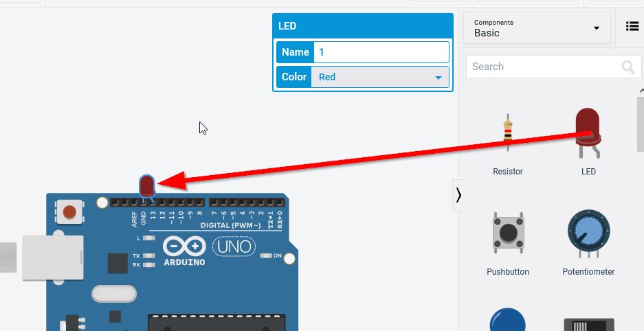
- I dragged an LED to test it. I connected it to pin 13 and GND.
- It blinks same as the built in LED.
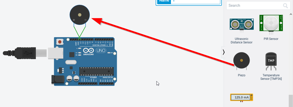
- Another useful component I tried is called Piezo. It is an electronic device that generates a voltage when it's physically deformed by a vibration, sound wave, or mechanical strain. I connected the positive electrode to pin 13, and the negative electrode to GND.
- To test the Piezo, I used a Nokia ringtone that is converted to Arduino code. I got it from a website. I provided the link below.
[click here](https://github.com/robsoncouto/arduino-songs/blob/master/nokia/nokia.ino).
If you want more converted sounds you can use this link below.
[click here](https://github.com/robsoncouto/arduino-songs).
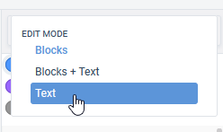
- To paste this code in Tinkercad, I changed the edit mode to Text.
- To make sure this code works with me, I did some changes to it.
- I changed the pin to 13 instead of 11.
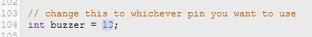
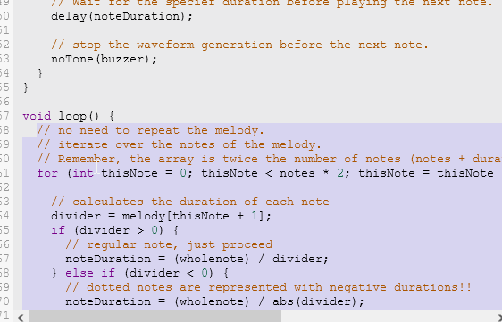
- The void loop() was empty, and I wanted the sound to play repeatedly, so I copied the code from void setup() to void loop().
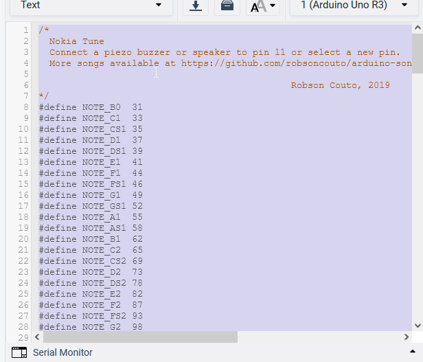
- This is the code after editing.
/*
  Nokia Tune
  Connect a piezo buzzer or speaker to pin 11 or select a new pin.
  More songs available at https://github.com/robsoncouto/arduino-songs

                                              Robson Couto, 2019
*/
#define NOTE_B0  31
#define NOTE_C1  33
#define NOTE_CS1 35
#define NOTE_D1  37
#define NOTE_DS1 39
#define NOTE_E1  41
#define NOTE_F1  44
#define NOTE_FS1 46
#define NOTE_G1  49
#define NOTE_GS1 52
#define NOTE_A1  55
#define NOTE_AS1 58
#define NOTE_B1  62
#define NOTE_C2  65
#define NOTE_CS2 69
#define NOTE_D2  73
#define NOTE_DS2 78
#define NOTE_E2  82
#define NOTE_F2  87
#define NOTE_FS2 93
#define NOTE_G2  98
#define NOTE_GS2 104
#define NOTE_A2  110
#define NOTE_AS2 117
#define NOTE_B2  123
#define NOTE_C3  131
#define NOTE_CS3 139
#define NOTE_D3  147
#define NOTE_DS3 156
#define NOTE_E3  165
#define NOTE_F3  175
#define NOTE_FS3 185
#define NOTE_G3  196
#define NOTE_GS3 208
#define NOTE_A3  220
#define NOTE_AS3 233
#define NOTE_B3  247
#define NOTE_C4  262
#define NOTE_CS4 277
#define NOTE_D4  294
#define NOTE_DS4 311
#define NOTE_E4  330
#define NOTE_F4  349
#define NOTE_FS4 370
#define NOTE_G4  392
#define NOTE_GS4 415
#define NOTE_A4  440
#define NOTE_AS4 466
#define NOTE_B4  494
#define NOTE_C5  523
#define NOTE_CS5 554
#define NOTE_D5  587
#define NOTE_DS5 622
#define NOTE_E5  659
#define NOTE_F5  698
#define NOTE_FS5 740
#define NOTE_G5  784
#define NOTE_GS5 831
#define NOTE_A5  880
#define NOTE_AS5 932
#define NOTE_B5  988
#define NOTE_C6  1047
#define NOTE_CS6 1109
#define NOTE_D6  1175
#define NOTE_DS6 1245
#define NOTE_E6  1319
#define NOTE_F6  1397
#define NOTE_FS6 1480
#define NOTE_G6  1568
#define NOTE_GS6 1661
#define NOTE_A6  1760
#define NOTE_AS6 1865
#define NOTE_B6  1976
#define NOTE_C7  2093
#define NOTE_CS7 2217
#define NOTE_D7  2349
#define NOTE_DS7 2489
#define NOTE_E7  2637
#define NOTE_F7  2794
#define NOTE_FS7 2960
#define NOTE_G7  3136
#define NOTE_GS7 3322
#define NOTE_A7  3520
#define NOTE_AS7 3729
#define NOTE_B7  3951
#define NOTE_C8  4186
#define NOTE_CS8 4435
#define NOTE_D8  4699
#define NOTE_DS8 4978
#define REST      0


// change this to make the song slower or faster
int tempo = 180;

// change this to whichever pin you want to use
int buzzer = 13;

// notes of the moledy followed by the duration.
// a 4 means a quarter note, 8 an eighteenth , 16 sixteenth, so on
// !!negative numbers are used to represent dotted notes,
// so -4 means a dotted quarter note, that is, a quarter plus an eighteenth!!
int melody[] = {

  // Nokia Ringtone
  // Score available at https://musescore.com/user/29944637/scores/5266155

  NOTE_E5, 8, NOTE_D5, 8, NOTE_FS4, 4, NOTE_GS4, 4,
  NOTE_CS5, 8, NOTE_B4, 8, NOTE_D4, 4, NOTE_E4, 4,
  NOTE_B4, 8, NOTE_A4, 8, NOTE_CS4, 4, NOTE_E4, 4,
  NOTE_A4, 2,
};

// sizeof gives the number of bytes, each int value is composed of two bytes (16 bits)
// there are two values per note (pitch and duration), so for each note there are four bytes
int notes = sizeof(melody) / sizeof(melody[0]) / 2;

// this calculates the duration of a whole note in ms
int wholenote = (60000 * 4) / tempo;

int divider = 0, noteDuration = 0;

void setup() {
  // iterate over the notes of the melody.
  // Remember, the array is twice the number of notes (notes + durations)
  for (int thisNote = 0; thisNote < notes * 2; thisNote = thisNote + 2) {

    // calculates the duration of each note
    divider = melody[thisNote + 1];
    if (divider > 0) {
      // regular note, just proceed
      noteDuration = (wholenote) / divider;
    } else if (divider < 0) {
      // dotted notes are represented with negative durations!!
      noteDuration = (wholenote) / abs(divider);
      noteDuration *= 1.5; // increases the duration in half for dotted notes
    }

    // we only play the note for 90% of the duration, leaving 10% as a pause
    tone(buzzer, melody[thisNote], noteDuration * 0.9);

    // Wait for the specief duration before playing the next note.
    delay(noteDuration);

    // stop the waveform generation before the next note.
    noTone(buzzer);
  }
}

void loop() {
  // no need to repeat the melody.
  // iterate over the notes of the melody.
  // Remember, the array is twice the number of notes (notes + durations)
  for (int thisNote = 0; thisNote < notes * 2; thisNote = thisNote + 2) {

    // calculates the duration of each note
    divider = melody[thisNote + 1];
    if (divider > 0) {
      // regular note, just proceed
      noteDuration = (wholenote) / divider;
    } else if (divider < 0) {
      // dotted notes are represented with negative durations!!
      noteDuration = (wholenote) / abs(divider);
      noteDuration *= 1.5; // increases the duration in half for dotted notes
    }

    // we only play the note for 90% of the duration, leaving 10% as a pause
    tone(buzzer, melody[thisNote], noteDuration * 0.9);

    // Wait for the specief duration before playing the next note.
    delay(noteDuration);

    // stop the waveform generation before the next note.
    noTone(buzzer);
  }

}
- This is a short video for the circuit.
2.3 CircuitPython
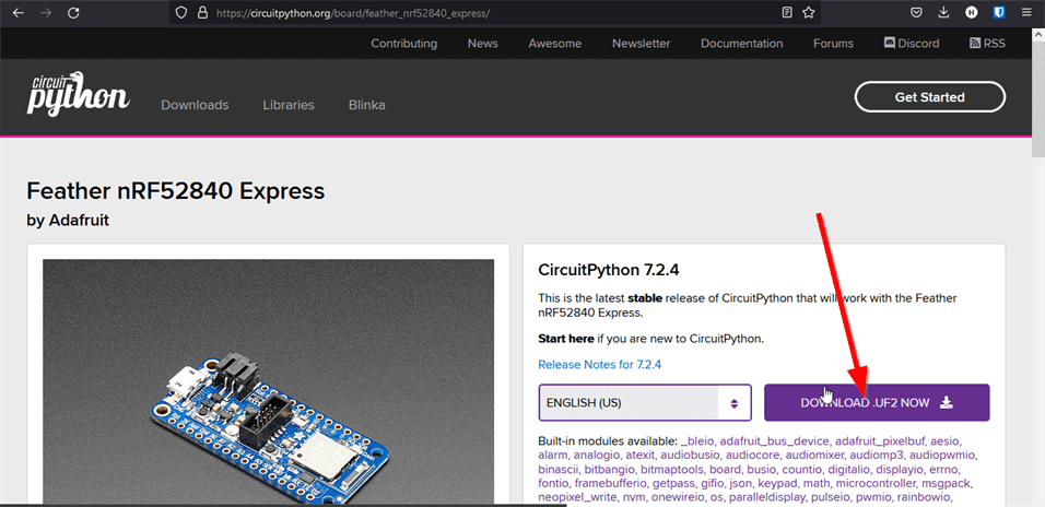
CircuitPython is an open-source derivative of the MicroPython programming language. CircuitPython is a full Python compiler and runtime that runs on the microcontroller hardware.
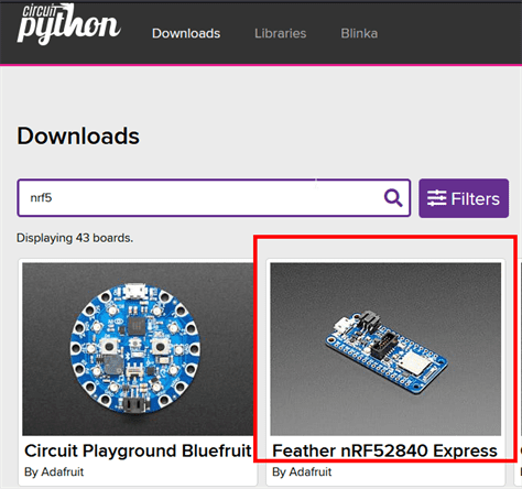
- I downloaded CircuitPython for my Adafruit.
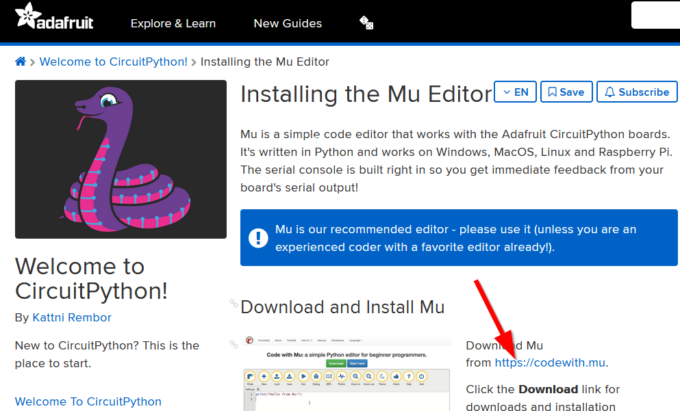
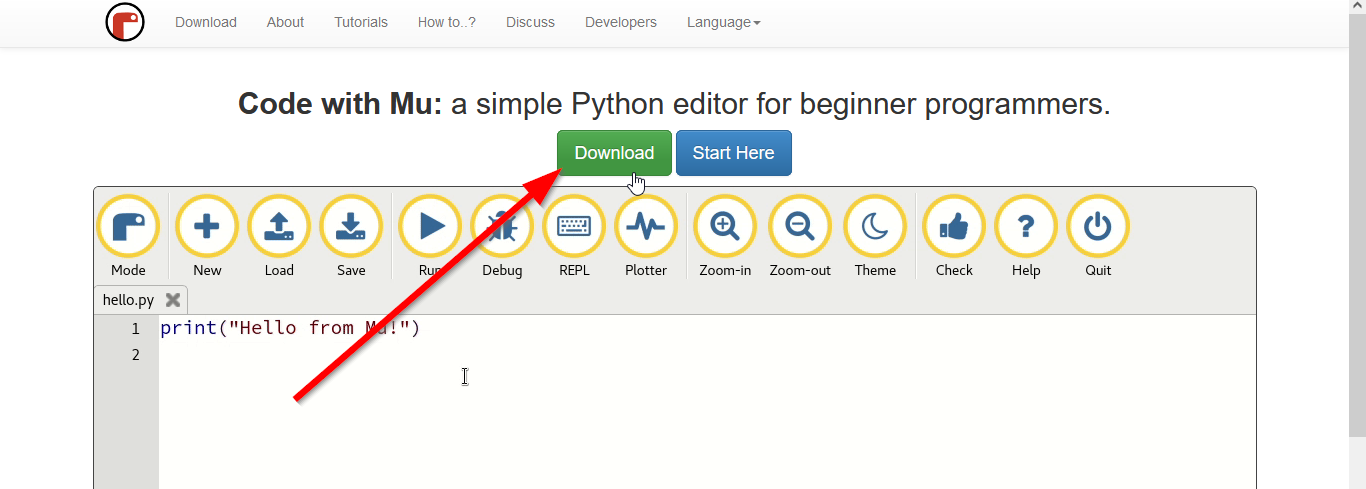
2.4 Mu Editor
MU Editor is a simple Python editor.
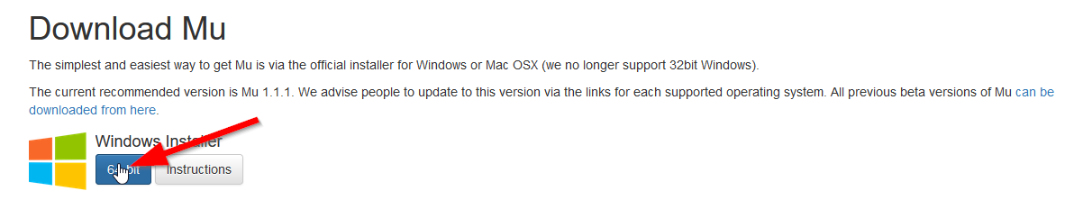
- I downloaded it and then installed it.
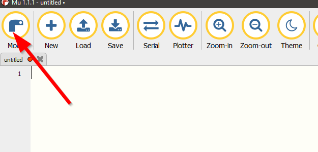
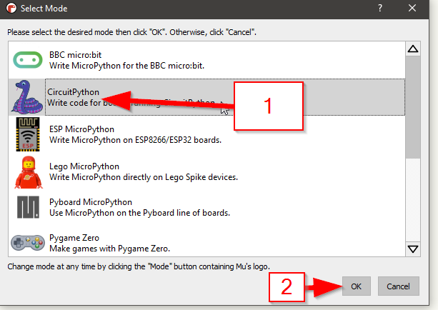
- I changed the Mu mode to CircuitPython.
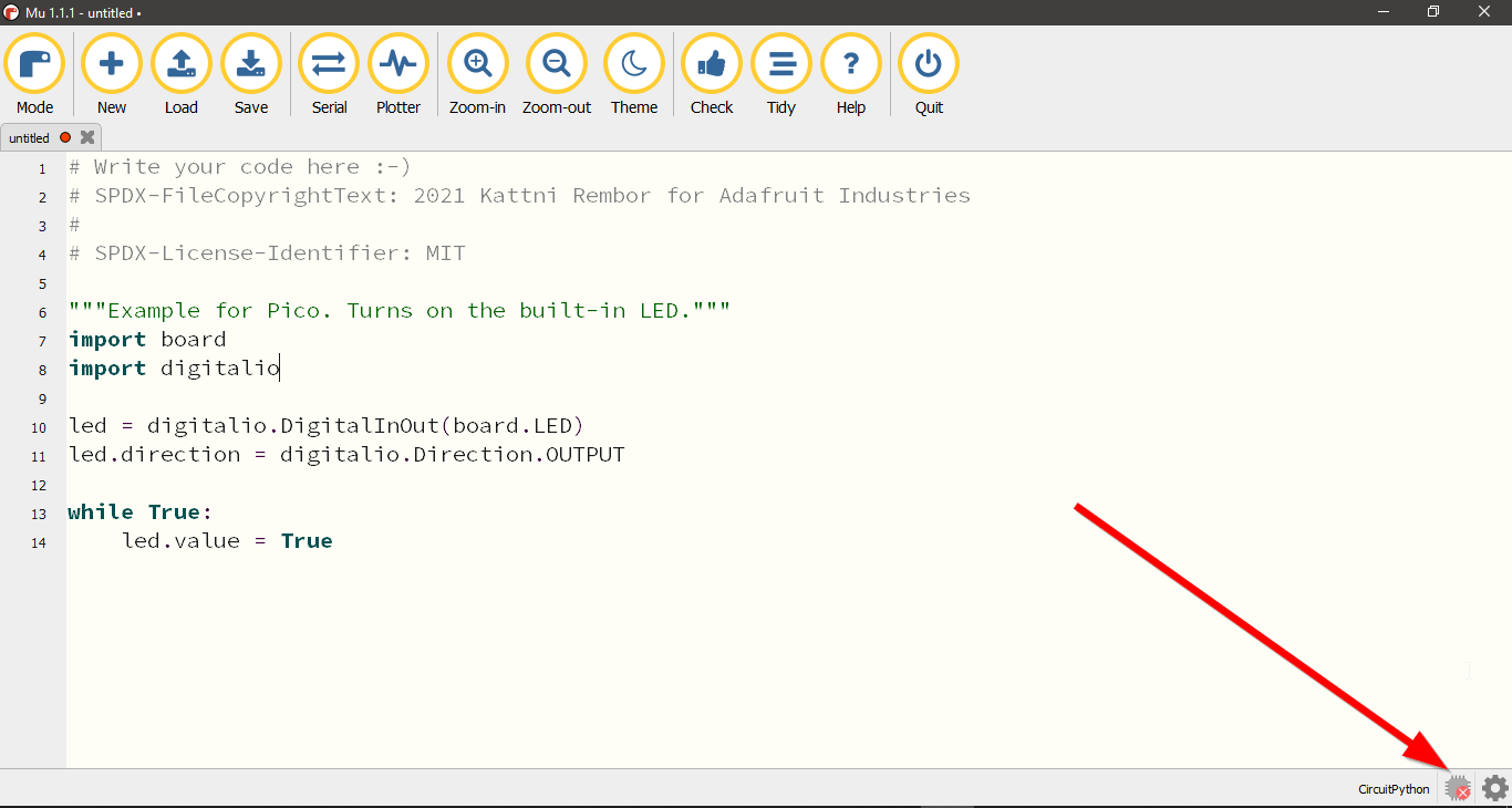
- I copied the blink code from the website below, and I pasted it in Mu Editor.
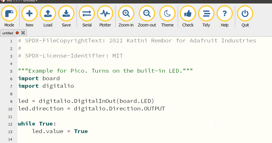
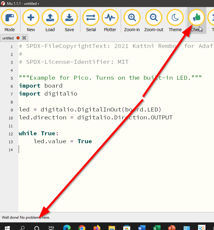
- This is the code that I used.
# SPDX-FileCopyrightText: 2021 Kattni Rembor for Adafruit Industries
#
# SPDX-License-Identifier: MIT

"""Example for Pico. Turns on the built-in LED."""
import board
import digitalio

led = digitalio.DigitalInOut(board.LED)
led.direction = digitalio.Direction.OUTPUT

while True:
    led.value = True
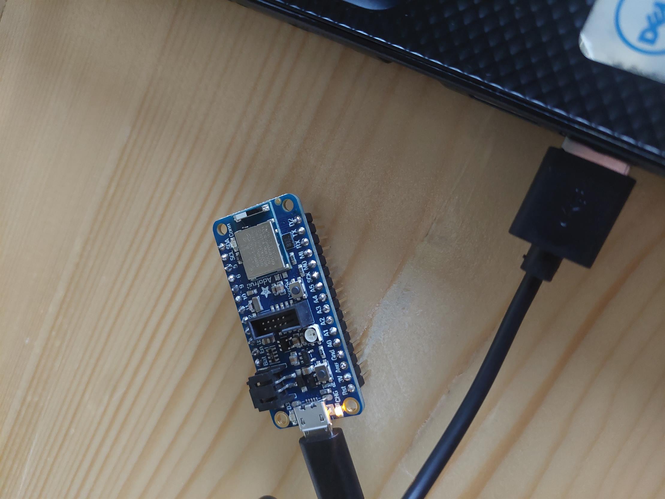
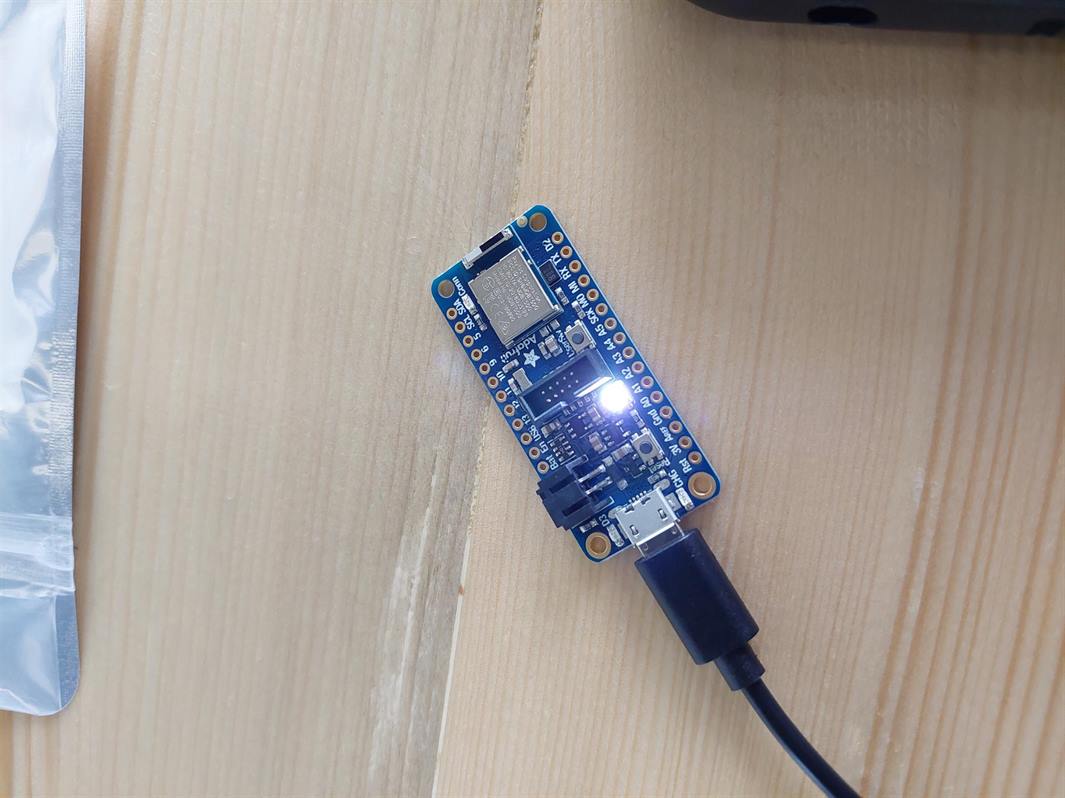
- I connected my Adafruit to my Laptop.
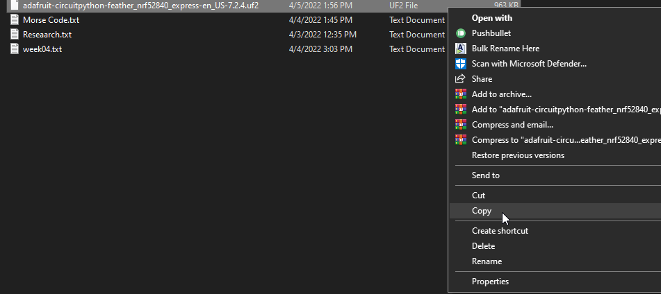
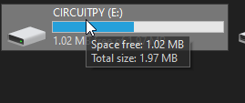
- The Mu Editor will not show a connected device. To solve this I copied the circuitpython file that I downloaded in 2.3 CircuitPythno to the Adafruit which should be shown as a drive in my Laptop.
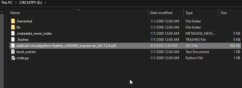
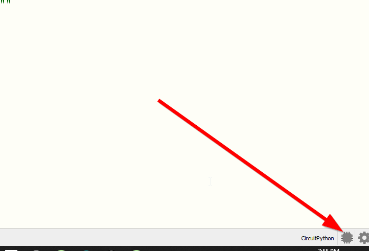
- This is the Adafruit drive.
- Now the Mu Editor can identify my Adafruit.
- To check the code I clicked on "Check" to see if there is any problem.
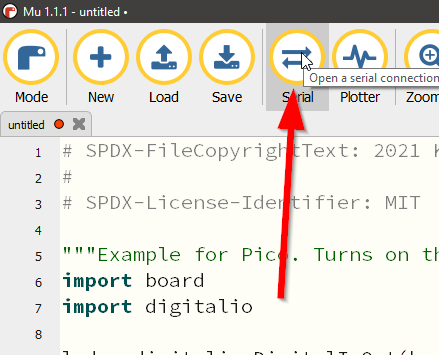
- To upload test the code on my Adafruit I clicked on Serial.
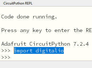
- I clicked on a key to continue.
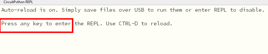
- After this I should write "import digitalio" to see the result on my Adafruit, but actually once I clicked on a key, the result showed up immediately.
2.5 Soldering
Soldering is a joining process used to join different types of metals together by melting solder.
We used soldering to solder the pins that came with our Adafruits.
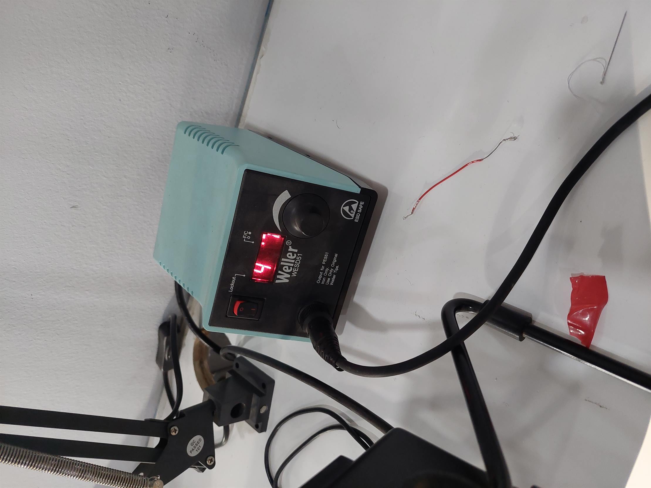
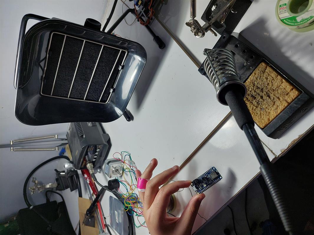
- This is the soldering device.
- These are the tools that we used.
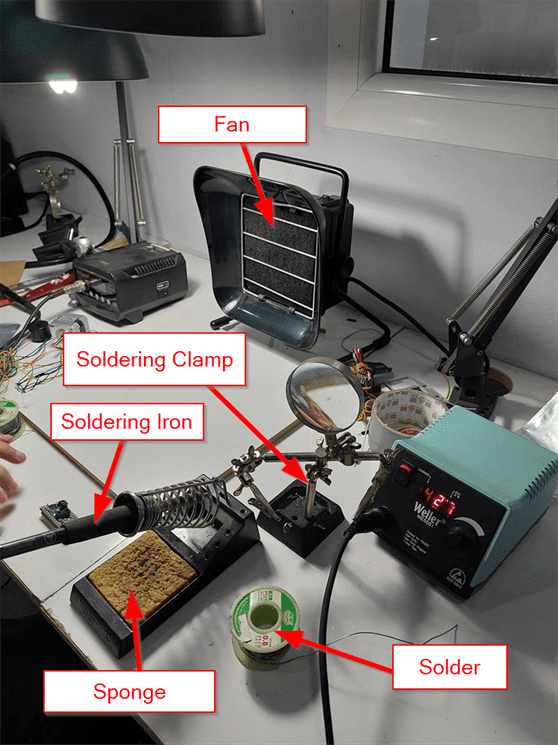
- The fan is used to remove the steam.
- The soldering clamp helps to hold the microcontroller.
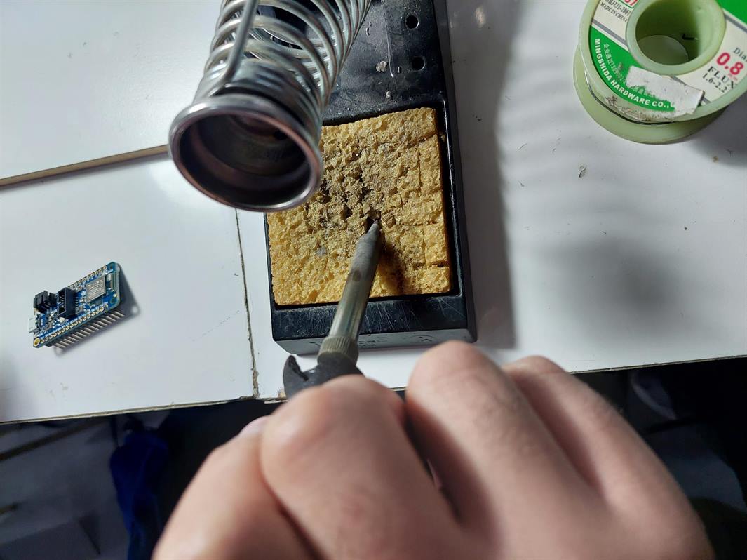
- The soldering iron is used for soldering. It produces a lot of heat so we need to be careful while using it.
- The sponge is useful for cleaning the soldering iron. We need to put a small amount of water on it first.
- The solder is the soldering material.
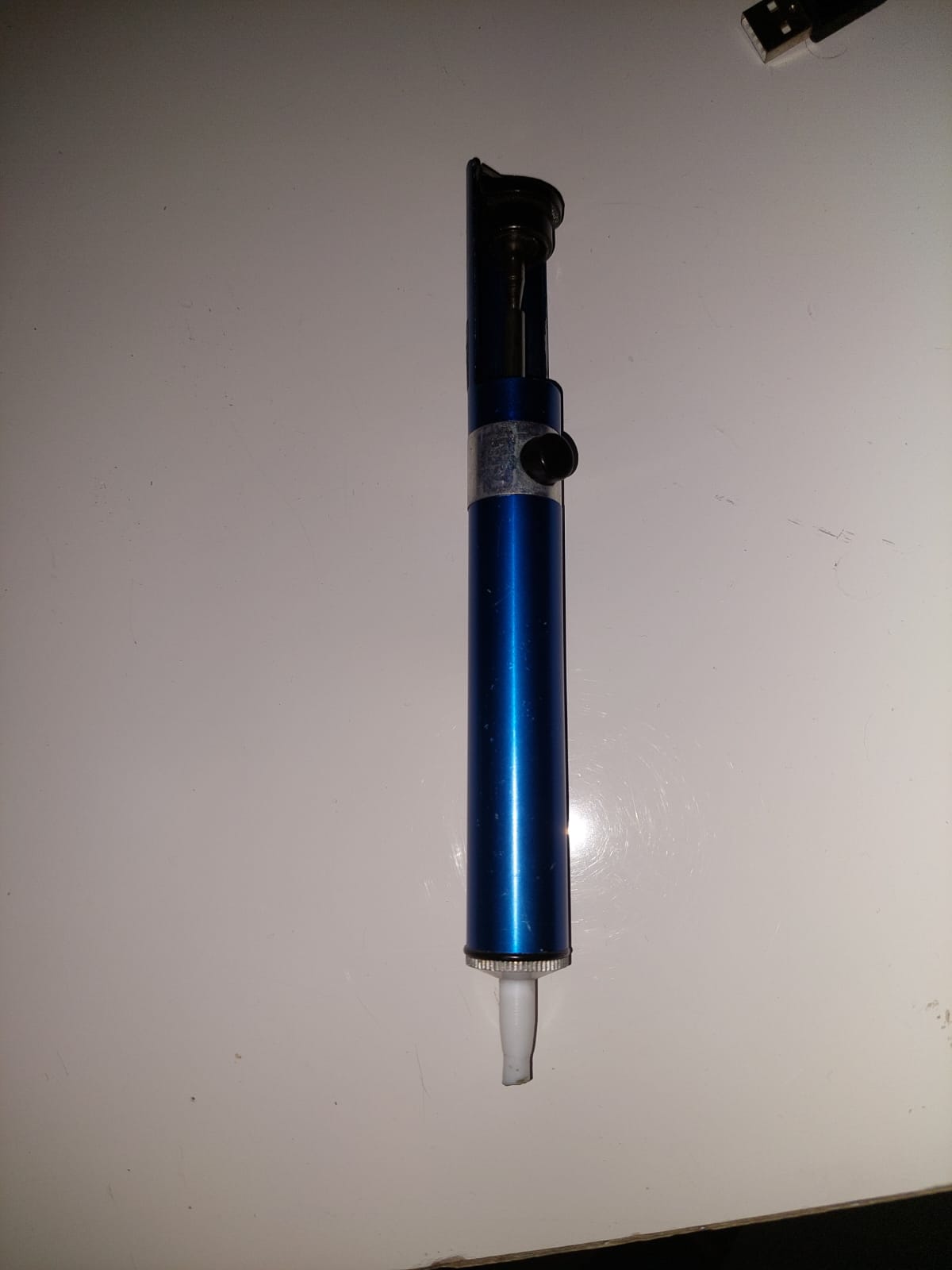
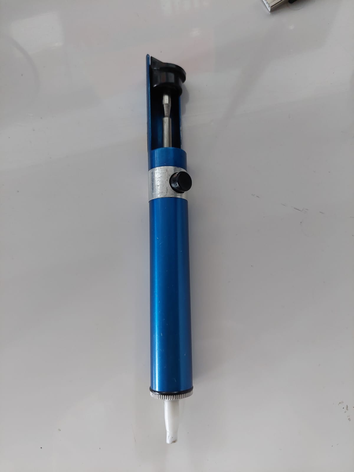
- There is another tool which is used to remove the extra soldering, this tool is called soldering remover. To use it we need first to slide down the part on the remover and then heat up the soldering and pressing the button on the remover.
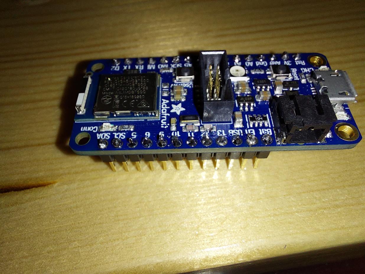
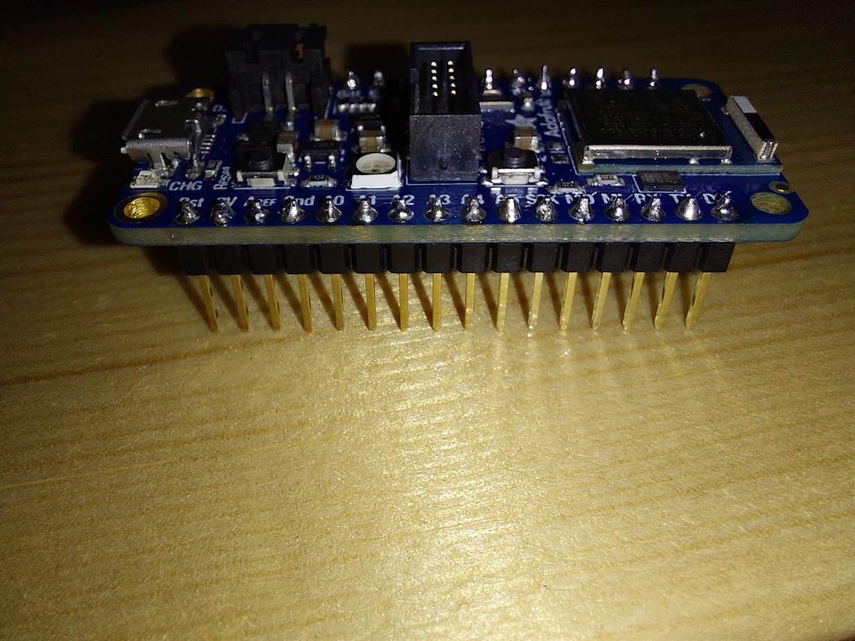
- I prepared the 16-pin first.
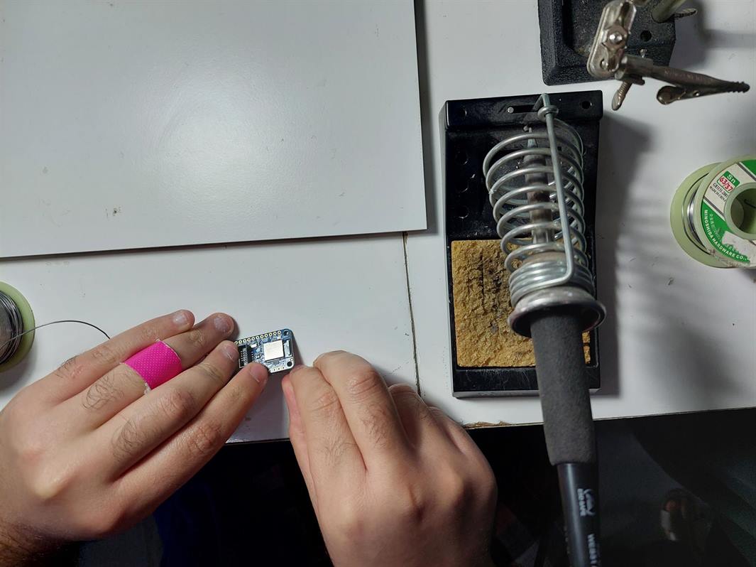
- I soldered the first and the last pins to hold the pins to the microcontroller and make the soldering easier.
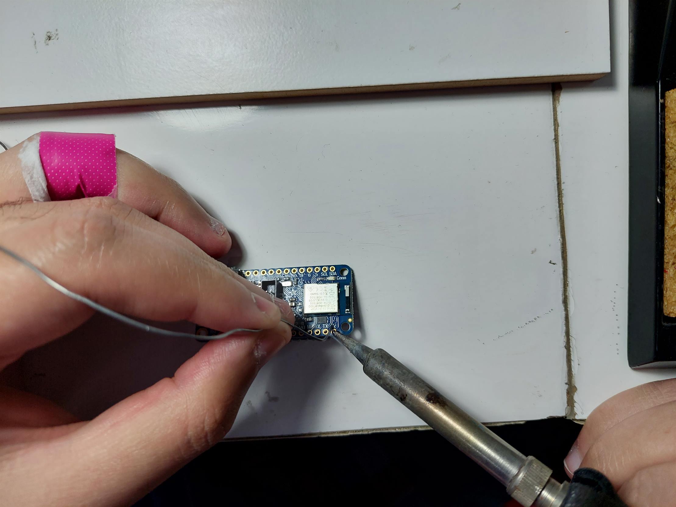
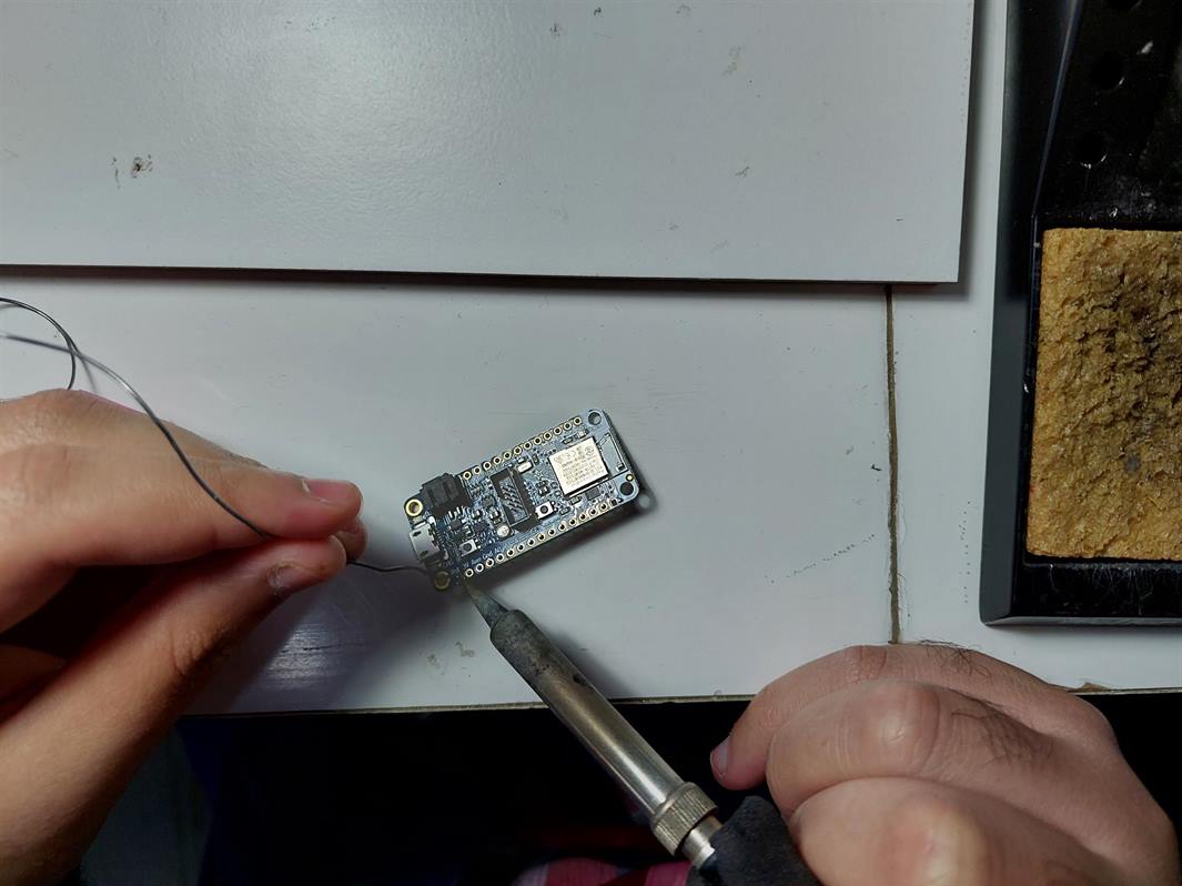
- I used the sponge to clean the soldering iron when I needed to.
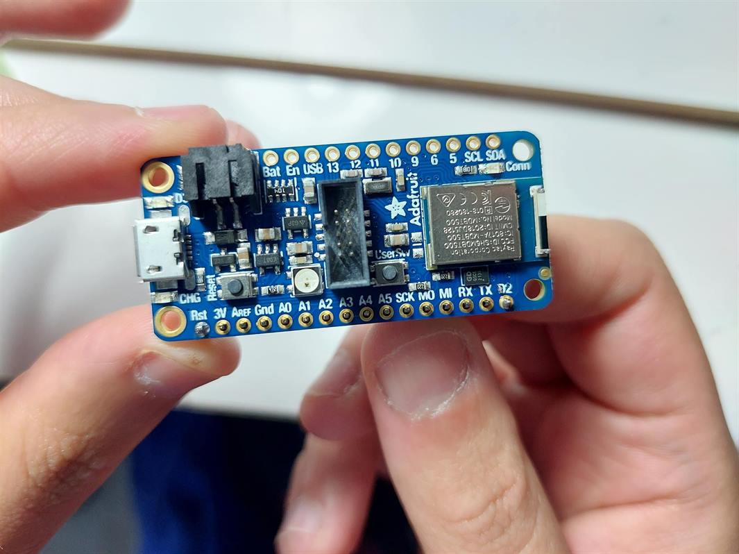
- I managed to solder the 16-pin..
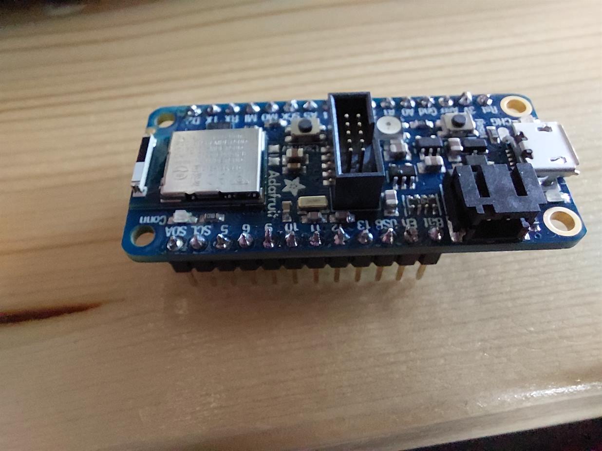
- We did not have a 12-pin so we had to break the other 16-pin to get a 12-pin only. I soldered it just like the 16-pin.
- While soldering I had some problems like adding extra solder or adding less solder. I used the soldering remover to remove the extra, and I added more solder to the needed pins. Our instructor Haitham Al-Nasser was with us and he gave us the feedback and help to get the best result.
- This is my final result.