7. Input & Output device
This week I learned about Input & Output device. The output device will give the result when the input is entered.
7.1 General Idea
Here are some examples for input and output devices:
| Input | Output |
|---|---|
| Mouse | Monitor |
| Keyboard | TV Screen |
| Switch | Projector |
| Microphone | Speakers |
The positive and the negative terminals in electronics can have different names too. The negative sign can be called ground or GND.
A microcontroller is a power supply. There are two different signals in the microcontroller, digital and analog and the picture below shows how these look like.
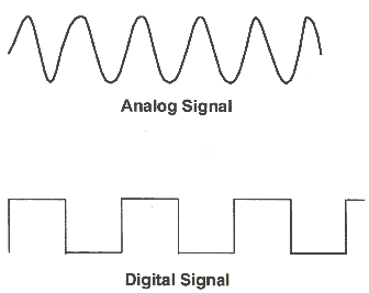
The digital signals values can be explained as high and low. For example let’s consider low as 0 and high as 10, and when a light switch is off the signal is 0 but when it is on the signal will be 10. No other options are available only off (0) and on (10).
The Analog signal however can have wide range of values. For example some lights have a switch with a circle and can turn on the lights with different intensity (Rotary Dimmer Switch). So the analog signal can have values in between the 0 and 10 for example.
The fan speed switch is another example for the analog signal.

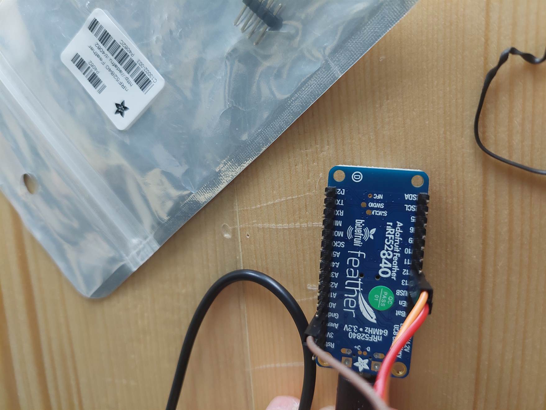
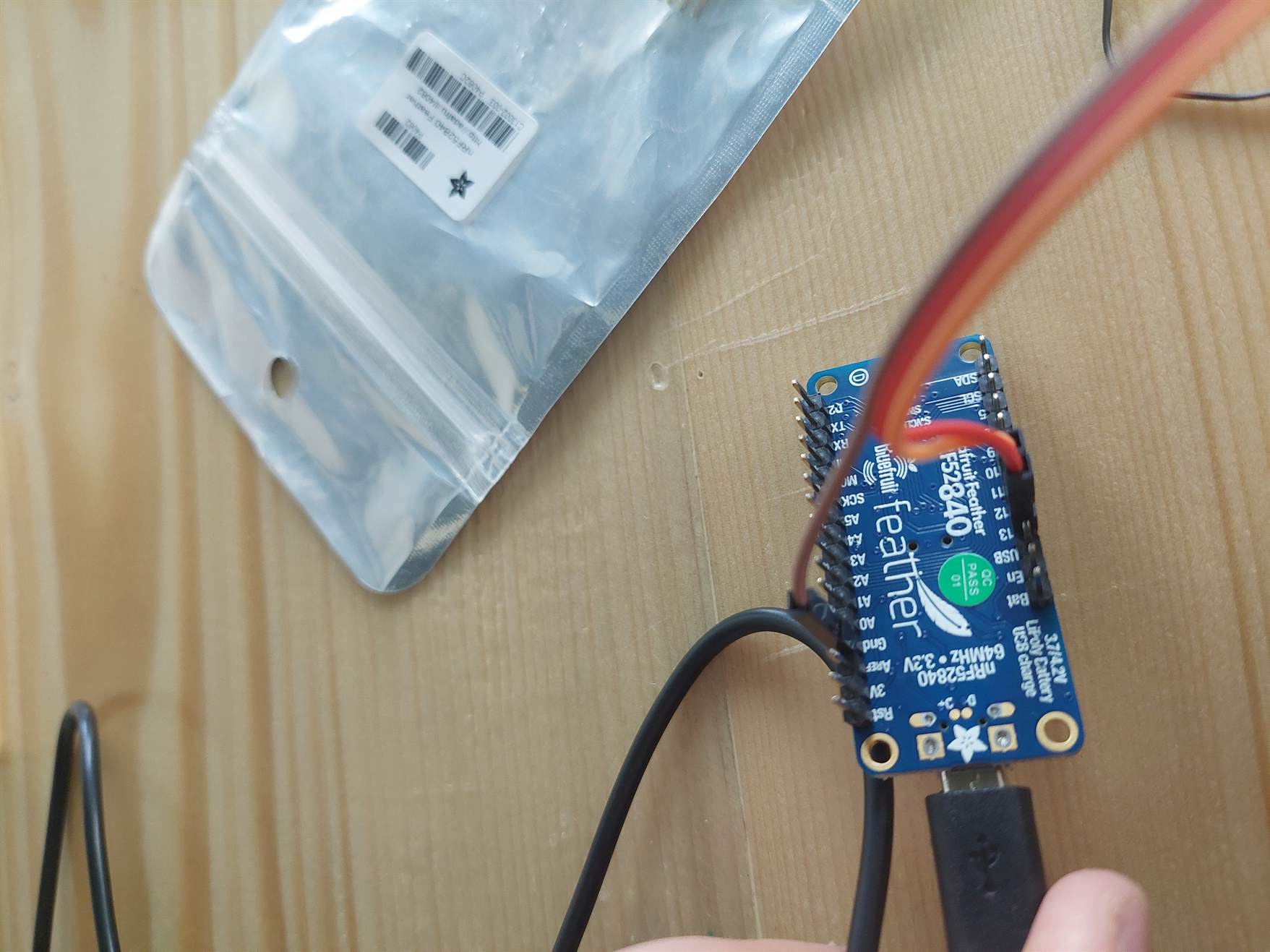
The Adafruit Feather has pins for both digital and analog signals.
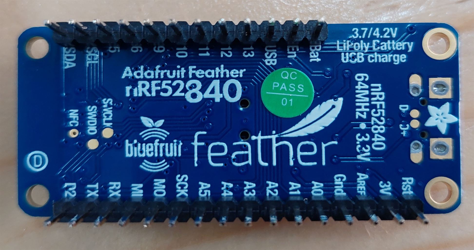
The pins with letter A (A0, A1, A2, …etc) are the analog pins. The pins with the numbers (5, 6, 9, 10, …etc) are the digital pins.
7.2 Output device
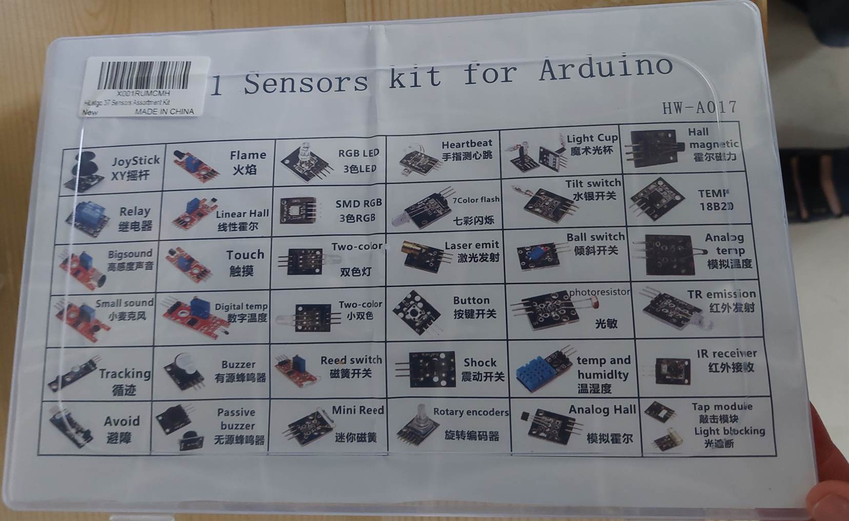
Our instructor Haitham provided us with the input (sensor) and output devices. I chose the Two-color LED as an output device. Below are the available sensors in Fab Lab Bahrain.
This is the two-color output that I used with the jumper wires. Jumper wires are wires that have connector pins at each end. There are different types of wires, male-to-male, male-to-female, female-to-female. The one that I used is the female-to-female.
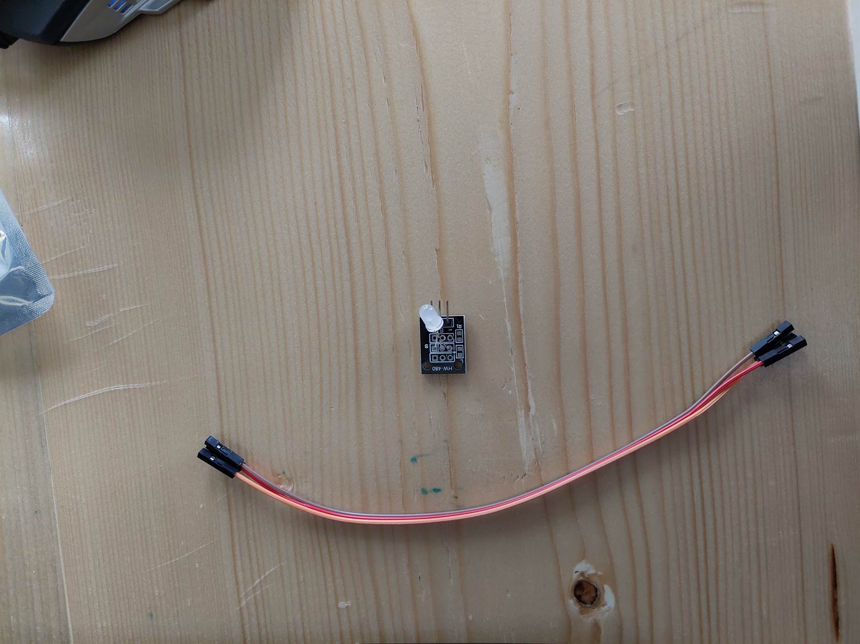
I connected the R pin to pin 12 and the G pin to pin 13 while the (-) to the GND.
To test the output device, I used different codes for blinking.
The first code was just a red blinking.
void setup() {
  // put your setup code here, to run once:
  // initialize digital pin LED_BUILTIN as an output.
  pinMode(12, OUTPUT);
  pinMode(13, OUTPUT);
}

void loop() {
  // put your main code here, to run repeatedly:
  digitalWrite(12, HIGH);
  digitalWrite(13, HIGH);
  delay(1000);
  digitalWrite(12, LOW);
  digitalWrite(13, LOW);
  delay(1000);
}
The second code is just a blinking with the green color and the red color.
int red_light_pin= 12;
int green_light_pin = 13;
void setup() {
  pinMode(red_light_pin, OUTPUT);
  pinMode(green_light_pin, OUTPUT);
}
void loop() {
  RGB_color(255, 0, 0); // Red
  delay(1000);
  RGB_color(0, 255, 0); // Green
  delay(1000);
  RGB_color(255, 0, 0); // Red
  delay(1000);
  RGB_color(0, 255, 0); // Green
  delay(1000);
  RGB_color(255, 0, 0); // Red
  delay(1000);
  RGB_color(0, 255, 0); // Green
  delay(1000);

  RGB_color(255, 0, 0); // Red
  delay(100);
  RGB_color(0, 255, 0); // Green
  delay(100);
  RGB_color(255, 0, 0); // Red
  delay(100);
  RGB_color(0, 255, 0); // Green
  delay(100);
  RGB_color(255, 0, 0); // Red
  delay(100);
  RGB_color(0, 255, 0); // Green
  delay(100);
  RGB_color(255, 0, 0); // Red
  delay(100);
  RGB_color(0, 255, 0); // Green
  delay(100);
  RGB_color(255, 0, 0); // Red
  delay(100);
  RGB_color(0, 255, 0); // Green
  delay(100);
  delay(1000);

}
void RGB_color(int red_light_value, int green_light_value)
 {
  analogWrite(red_light_pin, red_light_value);
  analogWrite(green_light_pin, green_light_value);
 }
I took the code from a website and edit it.
The third code shows the red and green and a mix of both.
int red_light_pin= 12;
int green_light_pin = 13;
void setup() {
  pinMode(red_light_pin, OUTPUT);
  pinMode(green_light_pin, OUTPUT);
}
void loop() {
  digitalWrite(red_light_pin,HIGH);
  digitalWrite(green_light_pin,LOW);
  delay(1000);

  digitalWrite(green_light_pin,HIGH);
  digitalWrite(red_light_pin,LOW);
  delay(1000);

  digitalWrite(green_light_pin,LOW);
  delay(1000);

  digitalWrite(red_light_pin,HIGH);
  digitalWrite(green_light_pin,HIGH);
  delay(1000);
}
I took the code from this video.
The fourth code is to change the LED color randomly.
int red = 9;
int green = 10;

void setup() {
  pinMode(red, OUTPUT);
  pinMode(green, OUTPUT);
}

void loop() {
  analogWrite(red, random(0, 255));
  analogWrite(green, random(0, 255));
  delay(1000);
}
I took the code from a website and edit it.
I did not take a video for this code.
Unfortunately, after the fourth code, I tried to do more tests and while doing so, I plugged the wires in the wrong pins and I damaged the output device because the 12 and 13 pins are close to a pin labeled as USB which destroyed the output device once I plugged it in. I should have been more careful.
7.3 Input Device
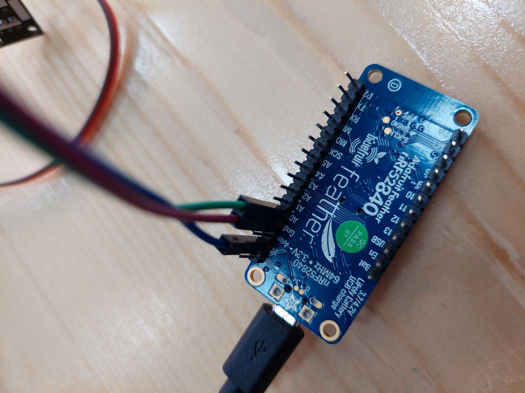
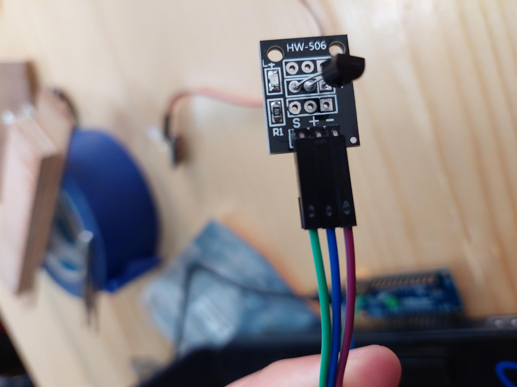
I used a temperature sensor as an input device.
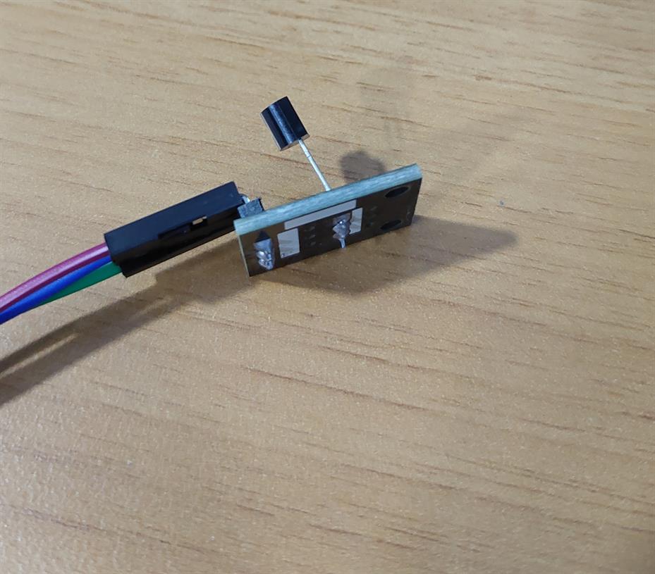
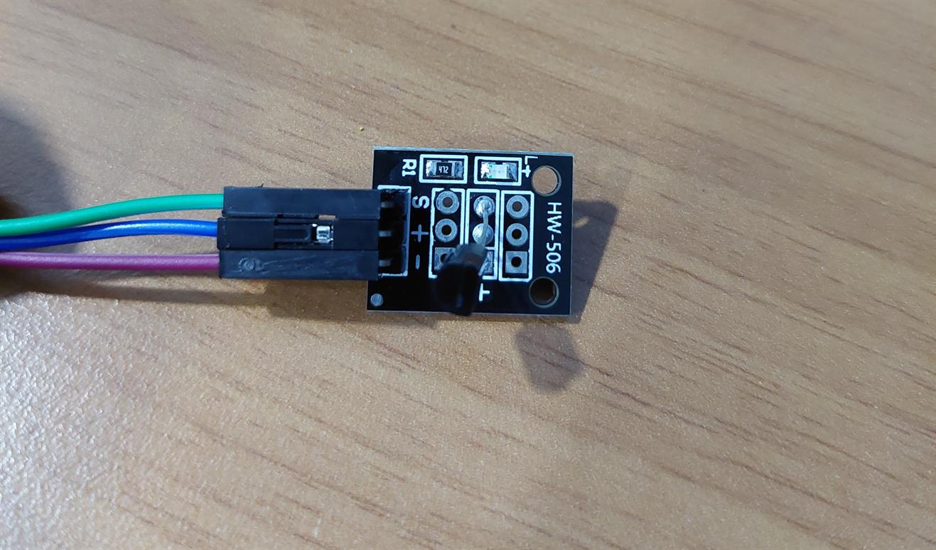
I connected the S pin with the A0 pin, the negative pin with the GND, and the positive pin with the 3V pin.
To test the sensor I needed to find a code and I used a code from a website.
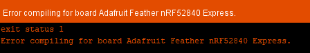
While uploading the code to the microcontroller, I faced an error and the code was not uploaded. To fix this, our instructor added a code above the void setup().
This is the needed code.
#include <SPI.h>
After uploading the code successfully, I clicked on Serial Monitor to test the sensor.
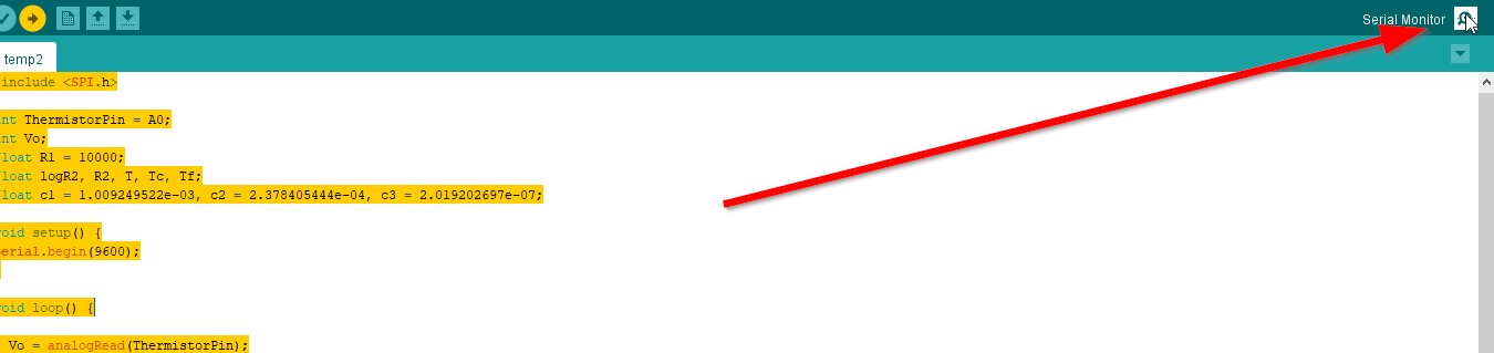
And it worked.
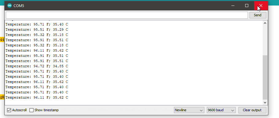
This is the code that I used to test the temperature sensor. I changed the pin to A0.
#include <SPI.h>

int ThermistorPin = A0;
int Vo;
float R1 = 10000;
float logR2, R2, T, Tc, Tf;
float c1 = 1.009249522e-03, c2 = 2.378405444e-04, c3 = 2.019202697e-07;

void setup() {
Serial.begin(9600);
}

void loop() {

  Vo = analogRead(ThermistorPin);
  R2 = R1 * (1023.0 / (float)Vo - 1.0);
  logR2 = log(R2);
  T = (1.0 / (c1 + c2*logR2 + c3*logR2*logR2*logR2));
  Tc = T - 273.15;
  Tf = (Tc * 9.0)/ 5.0 + 32.0;

  Serial.print("Temperature: ");
  Serial.print(Tf);
  Serial.print(" F; ");
  Serial.print(Tc);
  Serial.println(" C");

  delay(500);
}
My instructor Haitham asked me to try and edit the code to make the output device shows one color at a certain temperature and another color at a different temperature. For example, When the temperature is above 37 the LED should be red, and below 37 the LED should be green. Since I ruined the output device as I mentioned before in 7.2 Output device, I programmed the built in LED in the Adafruit instead. I made it blinking slowly while the temperature is below 37, and it blinks very fast when the temperature is above 37.
The problem here is I cannot use delay for the blinking time because the temperature reading will be affected too. I used it only with the fast blinking. For the slow blinking, I used a code that I found from a website.
I changed the interval to 2000.
Note: To record the videos, I changed the maximum temperature to a lower value just for recording.
#include <SPI.h>

// constants won't change. Used here to set a pin number:
const int ledPin =  LED_BUILTIN;// the number of the LED pin

// Variables will change:
int ledState = LOW;             // ledState used to set the LED

// Generally, you should use "unsigned long" for variables that hold time
// The value will quickly become too large for an int to store
unsigned long previousMillis = 0;        // will store last time LED was updated

// constants won't change:
//const long interval = 100;           // interval at which to blink (milliseconds)
const long interval2 = 2000;

int ThermistorPin = A0;
int Vo;
float R1 = 10000;
float logR2, R2, T, Tc, Tf;
float c1 = 1.009249522e-03, c2 = 2.378405444e-04, c3 = 2.019202697e-07;

void setup() {
  pinMode(LED_BUILTIN, OUTPUT);

Serial.begin(9600);
}

void loop() {

  Vo = analogRead(ThermistorPin);
  R2 = R1 * (1023.0 / (float)Vo - 1.0);
  logR2 = log(R2);
  T = (1.0 / (c1 + c2*logR2 + c3*logR2*logR2*logR2));
  Tc = T - 273.15;
  Tf = (Tc * 9.0)/ 5.0 + 32.0;

  Serial.print("Temperature: ");
  Serial.print(Tf);
  Serial.print(" F; ");
  Serial.print(Tc);
  Serial.println(" C");

  delay(500);


  // here is where you'd put code that needs to be running all the time.

  // check to see if it's time to blink the LED; that is, if the difference
  // between the current time and last time you blinked the LED is bigger than
  // the interval at which you want to blink the LED.
  unsigned long currentMillis = millis();

  if(Tc>37)
  {
  digitalWrite(LED_BUILTIN, HIGH);
  delay(50);
  digitalWrite(LED_BUILTIN, LOW);
  delay(50);
  }
  else if(Tc<=37)
  {
    if (currentMillis - previousMillis >= interval2) {
    // save the last time you blinked the LED
    previousMillis = currentMillis;

    // if the LED is off turn it on and vice-versa:
    if (ledState == LOW) {
      ledState = HIGH;
    } else {
      ledState = LOW;
    }

    // set the LED with the ledState of the variable:
    digitalWrite(ledPin, ledState);
  }
    }
}
This is a video for the code. It blinks slowly when the temperature is below 37, and blinks faster when it is above 37.
This is another video showing the temperature sensor too.
I did another test and asked my partner Iftikhar to give me his RGB output to test it with my temperature input. The light will be green when the temperature is below 37 and it will become red above 37.
This is the code that I used.
#include <SPI.h>

int red = 10;
int green = 11;
int blue = 12;

int ThermistorPin = A0;
int Vo;
float R1 = 10000;
float logR2, R2, T, Tc, Tf;
float c1 = 1.009249522e-03, c2 = 2.378405444e-04, c3 = 2.019202697e-07;

void setup() {
  pinMode(red, OUTPUT);
  pinMode(green, OUTPUT);
  pinMode(blue, OUTPUT);

Serial.begin(9600);
}

void loop() {

  Vo = analogRead(ThermistorPin);
  R2 = R1 * (1023.0 / (float)Vo - 1.0);
  logR2 = log(R2);
  T = (1.0 / (c1 + c2*logR2 + c3*logR2*logR2*logR2));
  Tc = T - 273.15-20;
  Tf = (Tc * 9.0)/ 5.0 + 32.0;

  Serial.print("Temperature: ");
  Serial.print(Tf);
  Serial.print(" F; ");
  Serial.print(Tc);
  Serial.println(" C");

  delay(500);


  if(Tc>37)
  {
  digitalWrite(red, HIGH);
  digitalWrite(blue, LOW);
  digitalWrite(green, LOW);
  }
  else if(Tc<=37)
  {
   digitalWrite(red, LOW);
  digitalWrite(blue, HIGH);
  digitalWrite(green, LOW);
  }

}
While testing I noticed that the temperature was too high and I think this is because I did not connect the ground wire for the output device because I needed to connect the ground wire for the input device. So, I modified the code by removing 20 degrees celsius.
This is a video for the test.
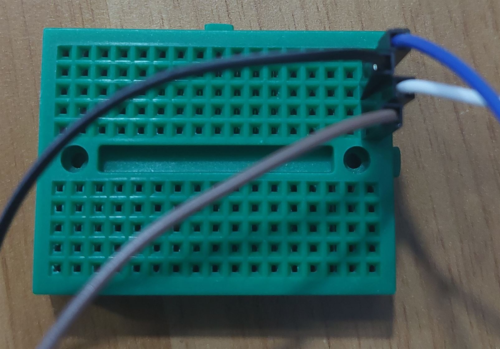
To solve the problem with the lack of ground pins, I used a breadboard. Now I can use different outputs together. I also added a buzzer to do more tests. If the temperature exceeds 37, then the buzzer will turn on. Otherwise it will stay off.
This is the breadboard which contains lines with holes. When a wire is connected (for example a ground wire), then the other holes in the row will be ground holes that can be used to connect other ground wires to it.
#include <SPI.h>

int red = 10;
int green = 11;
int blue = 12;
int buzz = 9;

int ThermistorPin = A0;
int Vo;
float R1 = 10000;
float logR2, R2, T, Tc, Tf;
float c1 = 1.009249522e-03, c2 = 2.378405444e-04, c3 = 2.019202697e-07;

void setup() {
  pinMode(red, OUTPUT);
  pinMode(green, OUTPUT);
  pinMode(blue, OUTPUT);
  pinMode(buzz, OUTPUT);

Serial.begin(9600);
}

void loop() {

  Vo = analogRead(ThermistorPin);
  R2 = R1 * (1023.0 / (float)Vo - 1.0);
  logR2 = log(R2);
  T = (1.0 / (c1 + c2*logR2 + c3*logR2*logR2*logR2));
  Tc = T - 273.15;
  Tf = (Tc * 9.0)/ 5.0 + 32.0;

  Serial.print("Temperature: ");
  Serial.print(Tf);
  Serial.print(" F; ");
  Serial.print(Tc);
  Serial.println(" C");

  delay(500);


  if(Tc>37)
  {
  digitalWrite(red, HIGH);
  digitalWrite(blue, LOW);
  digitalWrite(green, LOW);

  tone(buzz, 1000); // Send 1KHz sound signal...
  delay(1000);        // ...for 1 sec
  noTone(buzz);     // Stop sound...
  delay(1000);
  }
  else if(Tc<=37)
  {
   digitalWrite(red, LOW);
  digitalWrite(blue, HIGH);
  digitalWrite(green, LOW);
    digitalWrite(buzz,LOW);
  }

}
This is a video for the test.
The temperature sensor was not working properly, or maybe it is a problem with the code. Sometimes, the temperature suddenly jumps to very high temperature and returns back. Usually, the temperature is around 50 and 60 which is weird since the room temperature is much less. Also, when I try to hold the sensor to heat it, the temperature jumps to high values.
So, I used another sensor which is the temperature-humadity sensor. Still there was a problem too with the temperature readings. This sensor kept giving temperature values around 100. I tried to change the R1 value to 100000 and it gives a reasonable temperature around 30, but when I tried to hold it the temperature did not change. My instructor tried to use a hot air gun and a soldering iron but the temperature did not change too. We also tried to divide the temperature by 3.3 instead of changing R1 value but the problem still exists.
#include <SPI.h>

int red = 10;
int green = 11;
int blue = 12;
int buzz = 9;

int ThermistorPin = A0;
int Vo;
float R1 = 10000;
float logR2, R2, T, Tc, Tf;
float c1 = 1.009249522e-03, c2 = 2.378405444e-04, c3 = 2.019202697e-07;

void setup() {
  pinMode(red, OUTPUT);
  pinMode(green, OUTPUT);
  pinMode(blue, OUTPUT);
  pinMode(buzz, OUTPUT);

Serial.begin(9600);
}

void loop() {

  Vo = analogRead(ThermistorPin);
  R2 = R1 * (1023.0 / (float)Vo - 1.0);
  logR2 = log(R2);
  T = (1.0 / (c1 + c2*logR2 + c3*logR2*logR2*logR2));
  Tc = (T - 273.15)/3.33;
  Tf = (Tc * 9.0)/ 5.0 + 32.0;

  Serial.print("Temperature: ");
  Serial.print(Tf);
  Serial.print(" F; ");
  Serial.print(Tc);
  Serial.println(" C");

  delay(500);


  if(Tc>37)
  {
  digitalWrite(red, HIGH);
  digitalWrite(blue, LOW);
  digitalWrite(green, LOW);

  tone(buzz, 1000); // Send 1KHz sound signal...
  delay(1000);        // ...for 1 sec
  noTone(buzz);     // Stop sound...
  delay(1000);
  }
  else if(Tc<=37)
  {
   digitalWrite(red, LOW);
  digitalWrite(blue, HIGH);
  digitalWrite(green, LOW);
    digitalWrite(buzz,LOW);
  }

}
I found a code that works with the temperature-humadity sensor. The link for the website is below.
To make the code work I uncommented the code needed for the other temperature-humadity sensors and kept only the code for mine which is the DHT 11. I changed the pin to A0 and added the code for the RGB and the buzzer.
Also I had to install the DHT library for the adafruit (dht sensor library).

// Example testing sketch for various DHT humidity/temperature sensors

#include "DHT.h"
#include "SPI.h"
#define DHTPIN A0 // what digital pin we're connected to
// Uncomment whatever type you're using!
#define DHTTYPE DHT11 // DHT 11
//#define DHTTYPE DHT22 // DHT 22 (AM2302), AM2321
//#define DHTTYPE DHT21 // DHT 21 (AM2301)
// Connect pin 1 (on the left) of the sensor to +5V
// NOTE: If using a board with 3.3V logic like an Arduino Due connect pin 1
// to 3.3V instead of 5V!
// Connect pin 2 of the sensor to whatever your DHTPIN is
// Connect pin 4 (on the right) of the sensor to GROUND
// Connect a 10K resistor from pin 2 (data) to pin 1 (power) of the sensor
// Initialize DHT sensor.
// Note that older versions of this library took an optional third parameter to
// tweak the timings for faster processors. This parameter is no longer needed
// as the current DHT reading algorithm adjusts itself to work on faster procs.
DHT dht(DHTPIN, DHTTYPE);
int red = 10;
int green = 11;
int blue = 12;
int buzz = 9;

void setup() {
   Serial.begin(9600);
   Serial.println("DHTxx test!");
   dht.begin();
   pinMode(red, OUTPUT);
  pinMode(green, OUTPUT);
  pinMode(blue, OUTPUT);
  pinMode(buzz, OUTPUT);
}

void loop() {
   delay(1000); // Wait a few seconds between measurements
   float h = dht.readHumidity();
   // Reading temperature or humidity takes about 250 milliseconds!
   float t = dht.readTemperature();
   // Read temperature as Celsius (the default)
   float f = dht.readTemperature(true);
   // Read temperature as Fahrenheit (isFahrenheit = true)
   // Check if any reads failed and exit early (to try again).
   if (isnan(h) || isnan(t) || isnan(f)) {
      Serial.println("Failed to read from DHT sensor!");
      return;
   }

   Serial.print ("Humidity: ");
   Serial.println (h);
   Serial.print ("Temperature: ");
   Serial.print (t);
   Serial.print (" *C ");
   Serial.print (f);
   Serial.println (" *F");

   if(t>38)
   {
    digitalWrite(red, HIGH);
    digitalWrite(blue, LOW);
    digitalWrite(green, LOW);

    tone(buzz, 1000); // Send 1KHz sound signal...
    delay(1000);        // ...for 1 sec
    noTone(buzz);     // Stop sound...
    delay(1000);
    }
    else if (t<=38)
    {
      digitalWrite(red, LOW);
  digitalWrite(blue, HIGH);
  digitalWrite(green, LOW);
    digitalWrite(buzz,LOW);
      }
}