7. Input & Output device
This week we had to measure something by adding a sensor to a microcontroller board and read it. In addition, we had to add an output device to a microcontroller board and program it to do something.
Input devices
Input devices are the component of the computer system that accepts incoming data and instructions and converts them into a pattern of electrical signals in binary code that is understandable to a digital computer.
Application: In my project the distance that the ultrasonic sensor observe, sending the signal to the computer is what we call as output devise.
Output devices
Output devices are the component of computer system that converts the digitized signals into a form understandable to the user. The output devices are generally known as reverse of input devices. Output devices also send data from one computer system to another.
Application: In my project the buzzer when it starts buzzing and the LED light when it glows is what we call as output devises.
This information was taken from this website, you can read more about input and output too.
How does ultrasonic and buzzer work and communicate with the board in terms of electrical signals?
Ultrasonic
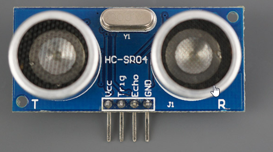
An ultrasonic sensor is a device that uses ultrasonic sound waves to determine the distance to an item. Ultrasonic sensors function by emitting a sound wave that is above the human hearing range. The sensor’s transducer functions as a microphone, receiving and transmitting ultrasonic sound. To deliver a pulse and receive the echo, our ultrasonic sensors, like many others, employ a single transducer. The sensor measures the time between delivering and receiving an ultrasonic pulse to estimate the distance to a target.
It operates by emitting an ultrasonic sound wave and waiting for it to bounce back off the target. The distance is then calculated based on the time delay between sound transmission and reception.
Distance = (Speed of sound * Time delay) / 2 is the formula used.
We double the distance formula by two because sound waves move in a circle, from the sensor to the sensor and back, doubling the actual distance.
The board is made of a thin insulating material clad with a thin layer of conductive copper that is shaped in such a way as to form the necessary conductors between the various components of the circuit.
To read more click on these links:
Buzzer
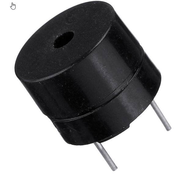
When talking about the interaction between the buzzer and the electric board, a tiny DC voltage is provided to the input pins, a resistor and transistor combination converts it to an oscillating signal. The inductor coil is used to amplify these oscillating impulses. The piezo ceramic disc experiences mechanical expansion and contraction in the radial direction when high voltage alternating impulses are applied. The metal plate bends in the opposite direction as a result of this. Sound waves are created when a metal plate bends and shrinks in opposite directions over time.
To read more click on these links:
Programming process used
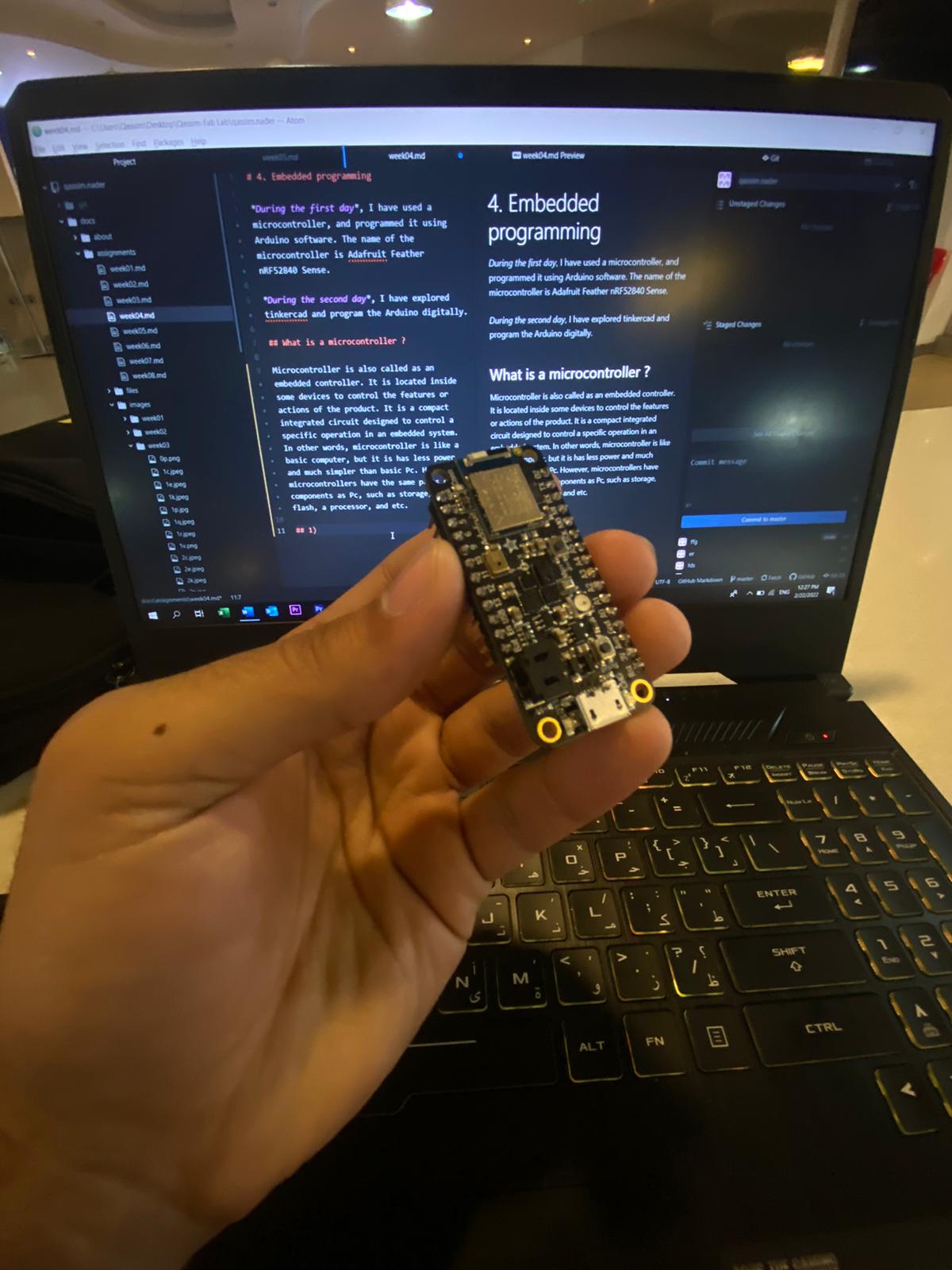
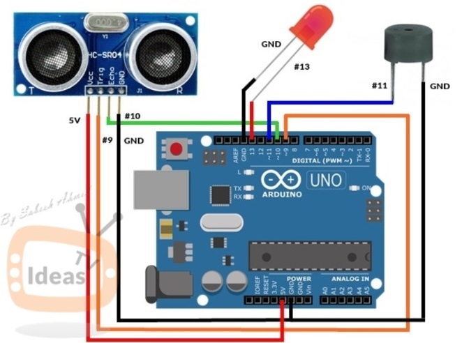
I have programmed my microcontroller (Adafruit Feather nRF52840 Sense) by using an ultrasonic sensor, buzzer, jumper wires, LED light, and a breadboard. The idea was taken from this link .
Whenever the ultrasonic sensor senses that an object is close to it (within the required distance in the code), the LED light glows and the buzzer starts producing a loud sound.
Adafruit Feather nRF52840 Sense
Ultrasonic sensor
Buzzer
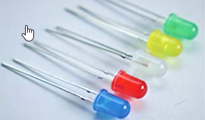
LED light
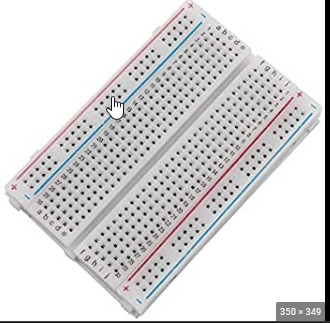
Breadboard
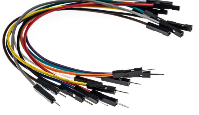
Jumper wires
Final connected design
Source Code
#include <SoftwareSerial.h>

// defines pins numbers
const int trigPin = 9;
const int echoPin = 10;
const int buzzer = 11;
const int ledPin = 13;

// defines variables
long duration;
int distance;
int safetyDistance;


void setup() {
pinMode(trigPin, OUTPUT); // Sets the trigPin as an Output
pinMode(echoPin, INPUT); // Sets the echoPin as an Input
pinMode(buzzer, OUTPUT);
pinMode(ledPin, OUTPUT);
Serial.begin(9600); // Starts the serial communication
}


void loop() {
// Clears the trigPin
digitalWrite(trigPin, LOW);
delayMicroseconds(2);

// Sets the trigPin on HIGH state for 10 micro seconds
digitalWrite(trigPin, HIGH);
delayMicroseconds(10);
digitalWrite(trigPin, LOW);

// Reads the echoPin, returns the sound wave travel time in microseconds
duration = pulseIn(echoPin, HIGH);

// Calculating the distance
distance= duration*0.034/2;

safetyDistance = distance;
if (safetyDistance <= 5){
  digitalWrite(buzzer, HIGH);
  digitalWrite(ledPin, HIGH);
}
else{
  digitalWrite(buzzer, LOW);
  digitalWrite(ledPin, LOW);
}

// Prints the distance on the Serial Monitor
Serial.print("Distance: ");
Serial.println(distance);
}
Preview the hero video
Problems and solutions
The main problems that I faced were:
-
I have connected the buzzer to a wrong position. The problem was that my partner Talal and I thought that there was a big issue in our circut and we were concentrating on other stuff while ignoring the fact that we should check our wires if they were located on the correct positions. After two days, we built the circuit again and realized the issue.
-
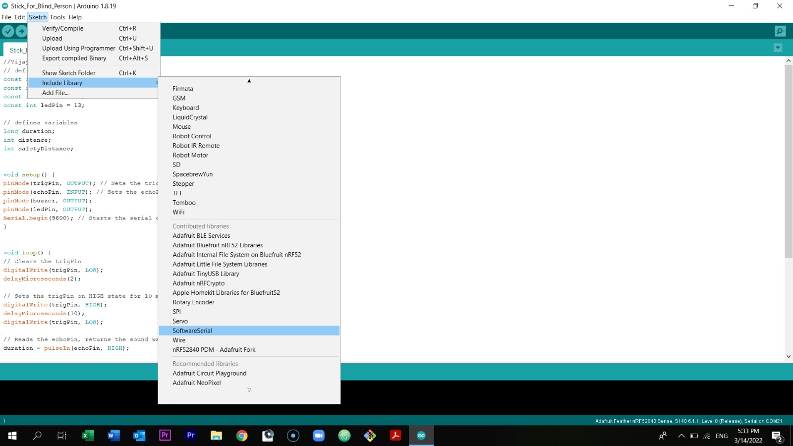
AFter placing the wires in their correct positions, it didn’t work too. After doing some researches and asking the instructors Haitham and Abdullah, we have figured out the issue. The issue was that the arduine software couldn’t recognize the serial command. I did not include the software serial from the library in the code. Here is the way of solving this issue:
Select sketch.
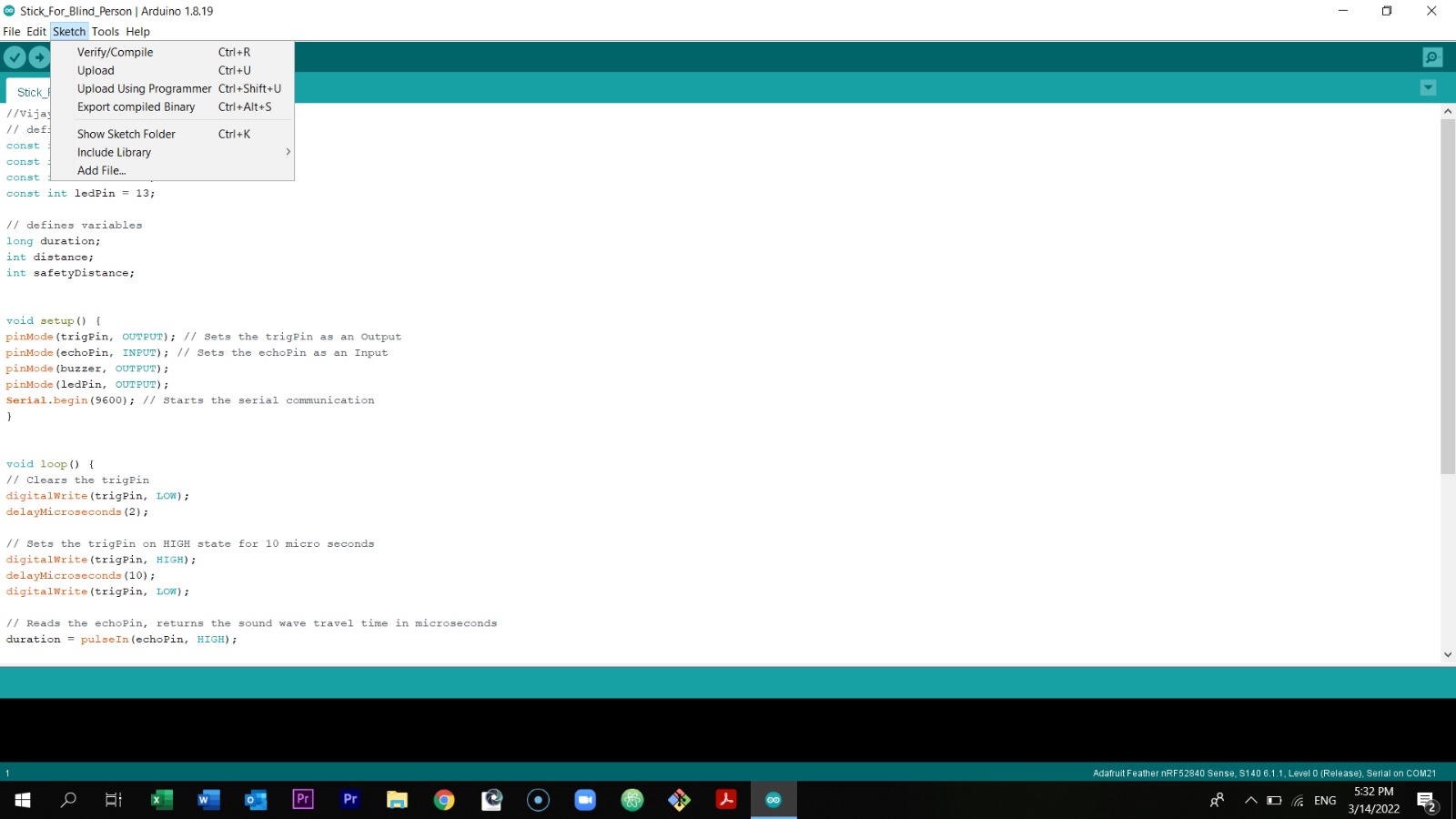
Select include library.
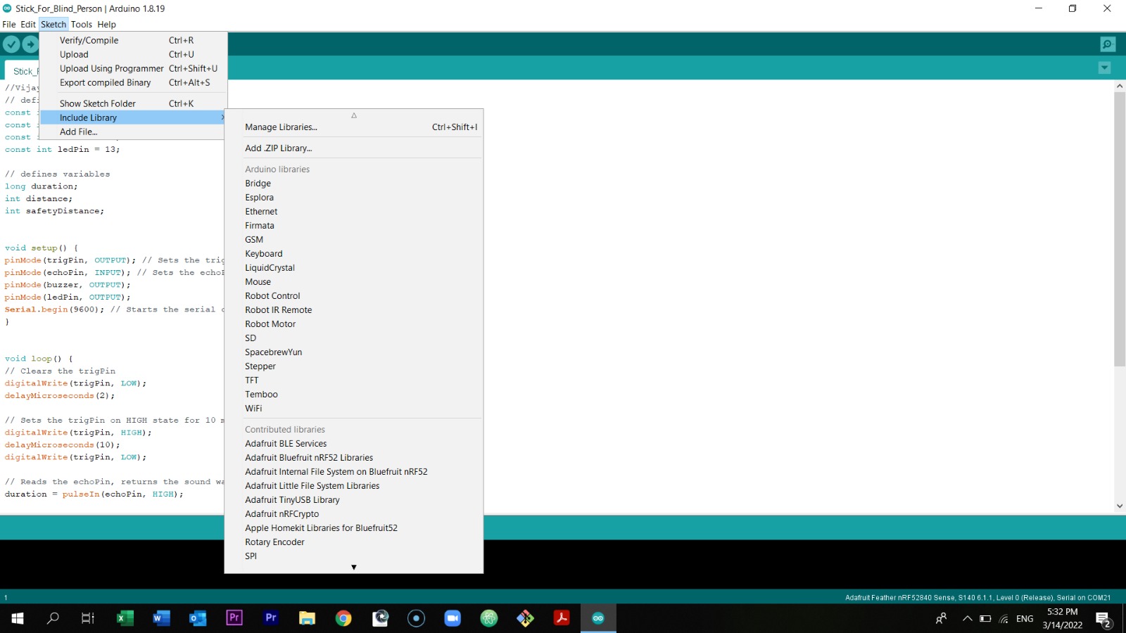
Then select Softwareserial.