4. Embedded programming
I spent this past week working on the Arduino IDE coding language and programming a microcontroller.
Microcontroller
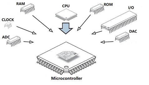
What is Microcontroller: A microcontroller is a compact, reasonably priced microcomputer that is made to carry out the particular functions of embedded systems, such as displaying microwave information and receiving remote signals, among others. A general microcontroller has a processor, memory (RAM, ROM, EPROM), Serial ports, peripherals (timers, counters, etc.), and other components.
Types of Microcontrollers
The memory, architecture, bits, and instruction sets of microcontrollers are used to categorize them into different groups. The list of their types is shown below.
Bit
Based on bit configuration, the microcontroller is further divided into three categories:
-
8-bit microcontroller: This type of microcontroller is used to execute arithmetic and logical operations like addition, subtraction, multiplication division, etc. For example, Intel 8031 and 8051 are 8 bits microcontroller.
-
16-bit microcontroller: This type of microcontroller is used to perform arithmetic and logical operations where higher accuracy and performance is required. For example, Intel 8096 is a 16-bit microcontroller.
-
32-bit microcontroller: This type of microcontroller is generally used in automatically controlled appliances like automatic operational machines, medical appliances, etc.
Memory
based on the memory configuration, the microcontroller is further divided into two categories:
-
External memory microcontroller: This type of microcontroller is designed in such a way that they do not have a program memory on the chip. Hence, it is named as external memory microcontroller. For example: Intel 8031 microcontroller.
-
Embedded memory microcontroller: This type of microcontroller is designed in such a way that the microcontroller has all programs and data memory, counters and timers, interrupts, I/O ports are embedded on the chip. For example: Intel 8051 microcontroller.
Instruction Set
Based on the instruction set configuration, the microcontroller is further divided into two categories:
-
CISC: CISC stands for complex instruction set computer. It allows the user to insert a single instruction as an alternative to many simple instructions.
-
RISC: RISC stands for Reduced Instruction Set Computers. It reduces the operational time by shortening the clock cycle per instruction.
Applications of Microcontrollers:
-
Light sensing and controlling devices like LED.
-
Temperature sensing and controlling devices like microwave oven, chimneys.
-
Fire detection and safety devices like Fire alarm.
-
Measuring devices like Volt Meter
Arduino
What is Arduino: Arduino is an open-source electronics platform based on easy-to-use hardware and software. Arduino boards are able to read inputs - light on a sensor, a finger on a button, or a Twitter message - and turn it into an output - activating a motor, turning on an LED, publishing something online. You can tell your board what to do by sending a set of instructions to the microcontroller on the board. To do so you use the Arduino programming language (based on Wiring), and the Arduino Software (IDE), based on Processing.
Why Arduino ?
- Inexpensive
- Cross-platform
- Simple, clear programming environment
- Open source and extensible software
- Open source and extensible hardware
Datasheet
This is the datasheet that I read Arduino MKR WiFi 1010 Datasheet
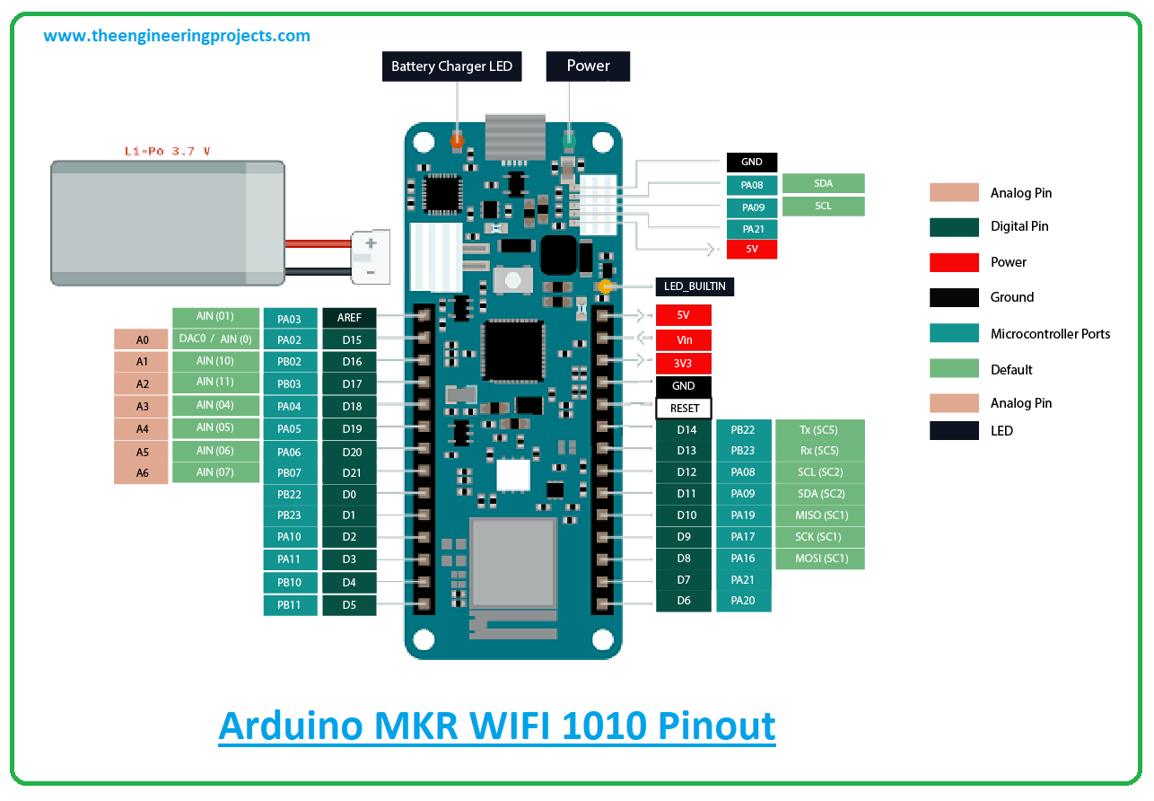
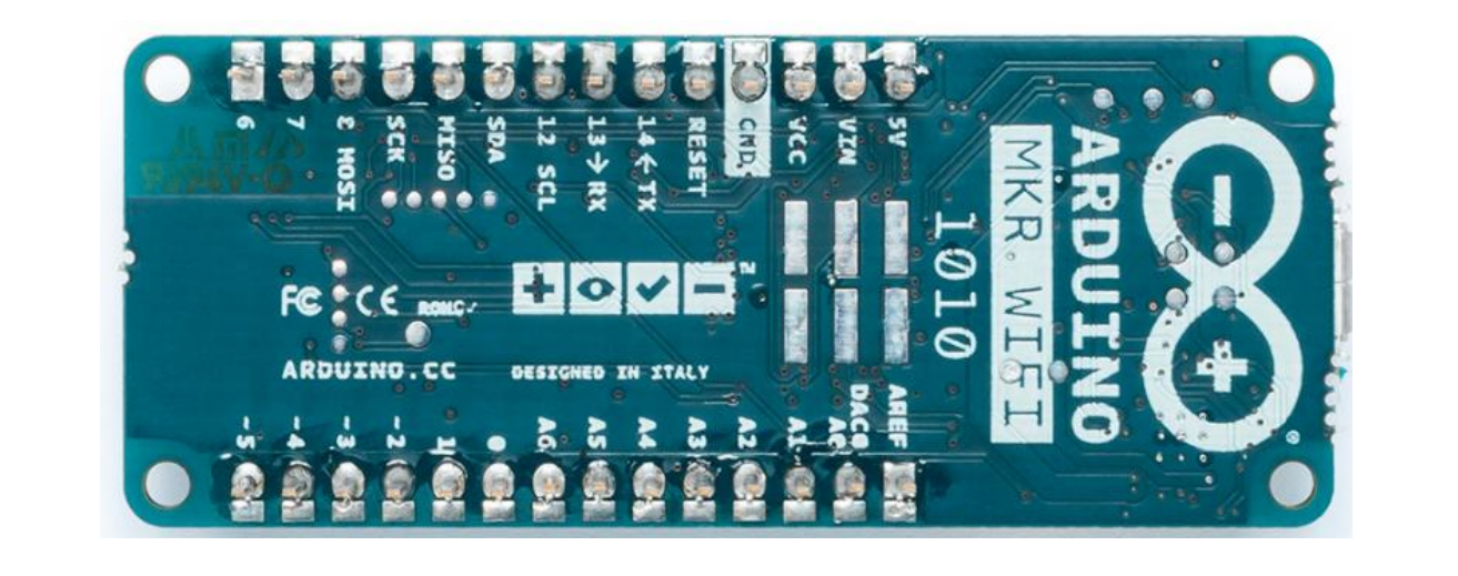
Arduino MKR WiFi 1010: The MKR WiFi 1010 is a great choice for any beginner, maker or professional to get started with Internet of Things (IoT). Using the popular Arm® Cortex®-M0 32-bit SAMD21 processor, the Nina W102 Module, a crypto chip (the ATECC508), and a 2MByte SPI Flash. The board is part of the MKR family.
Regarding the board, Like most Arduino MKR form factor boards the MKR WiFi 1010 can be powered via USB, via headers or connecting a Lithium or Lithium Polymer battery to the embedded battery charger (the BQ24195L). Also, Arduino MKR WiFi 1010 only supports 3.3V I/Os and is NOT 5V tolerant. Please make sure you are not directly connecting 5V signals to this board, or it will be damaged.
It’s applications:
-
Bluetooth: The communications chipset on the MKR WiFi 1010 is something pretty unique. In the world of microcontroller platforms, since this can be both a BLE and Bluetooth® client and host device.
-
WiFi: The WiFi connectivity is performed with a module from u-blox, the NINA-W10, a low power chipset operating in the 2.4GHz range.
-
IoT: Whether you are looking at building a sensor network connected to your office or home router, or if you want to create a BLE device sending data to a cell phone, the MKR WiFi 1010 is your one-stop-solution for many of the basic IoT application scenarios.
Regarding the pins
I/O Pins: The Arduino MKR WiFi 1010 provides 8 Digital I/O pins, pins 0 - 7. It has 7 Analog Input pins (ADC 8/10/12 bit), pins A0 / A6 and 1 Analog Output pin (DAC 10 bit), the pin identified with DAC0/A0. The DC current per I/O pin is 7mA. Pins 0, 1, 2, 3, 4, 5, 6, 7, 8, 10, 12, 18, 19 are PWM pins. This informations was taken from another datasheet. Click here if you are interseted.
Programming Using ARDUINO IDE
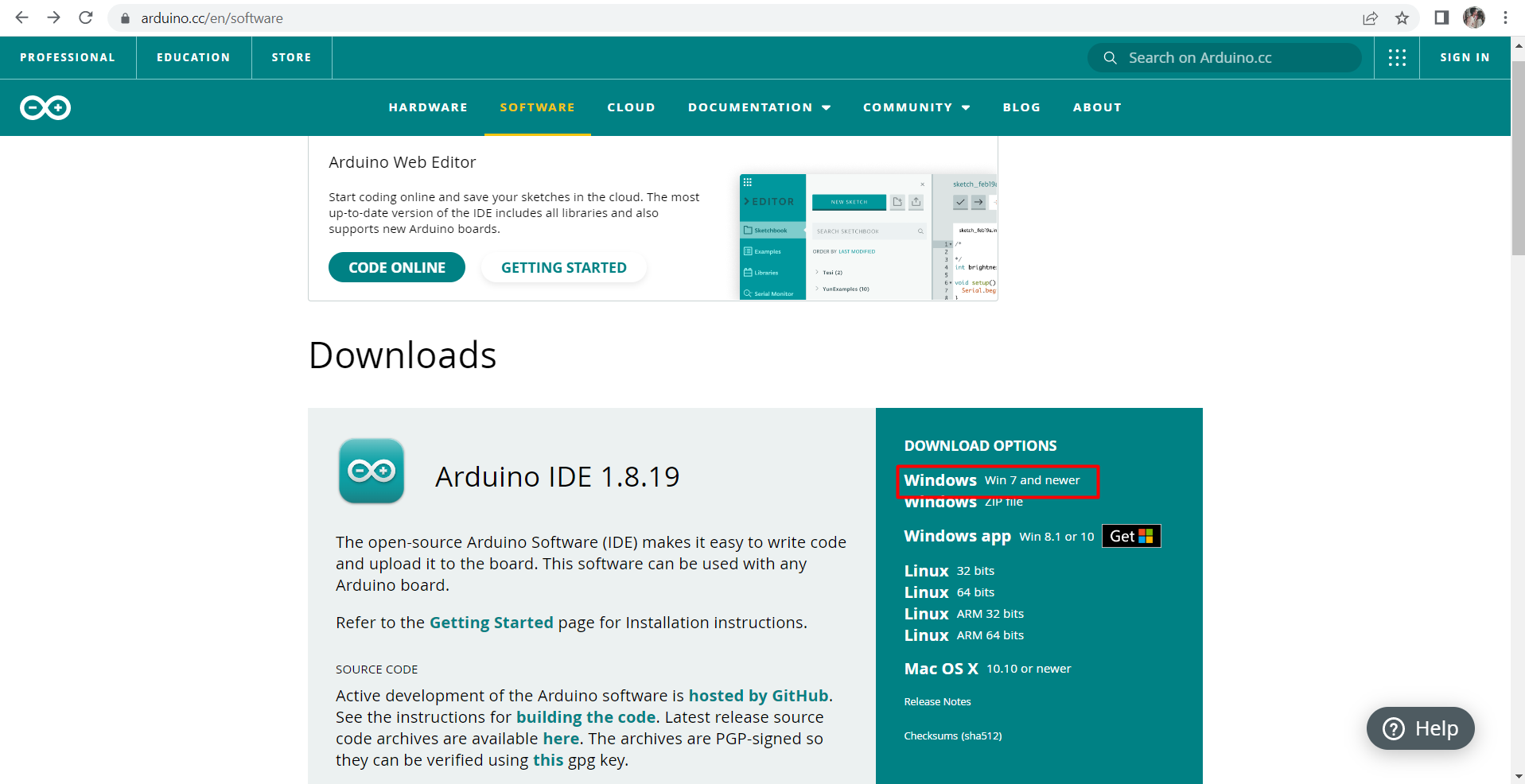
First, before starting programming, you need to download the software from the provided link here Arduino IDE

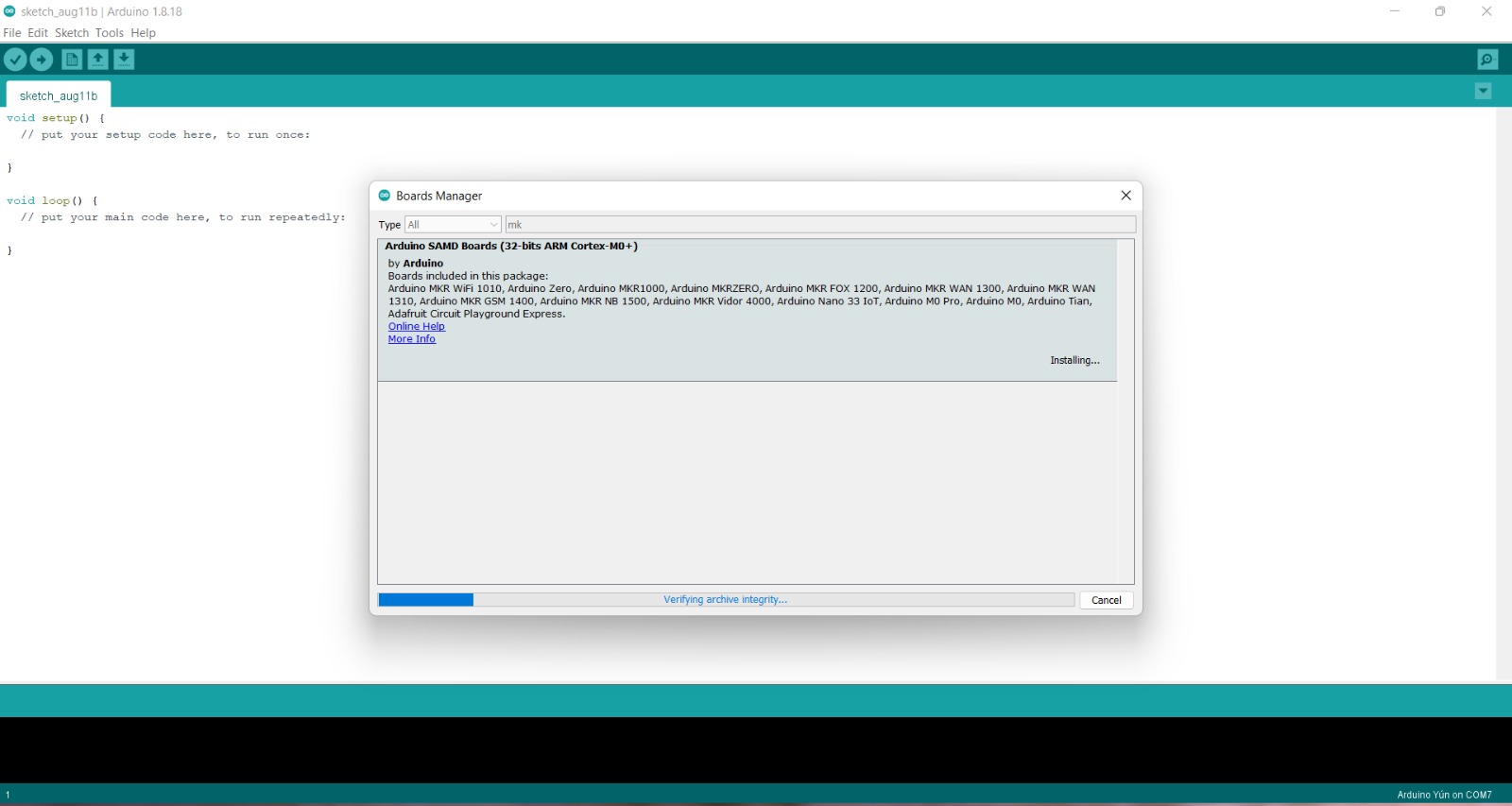
After installing the software, download the board to the Arduino IDE
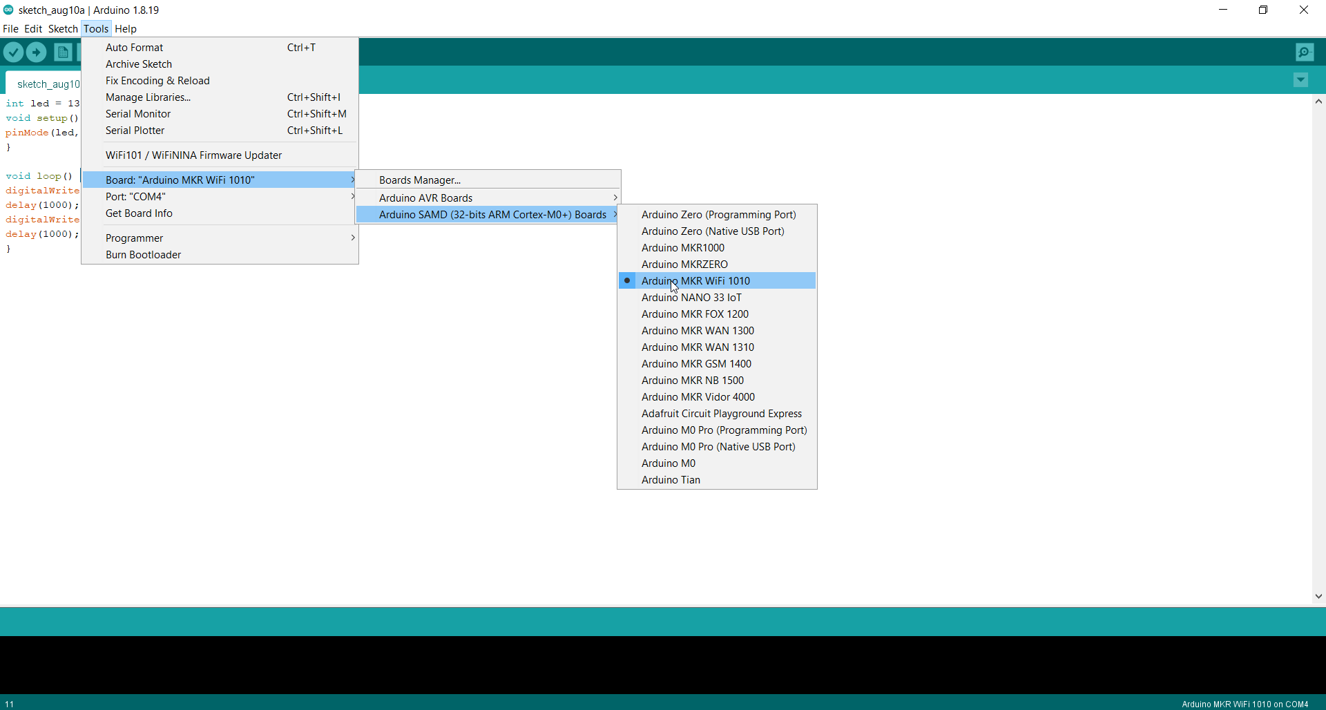
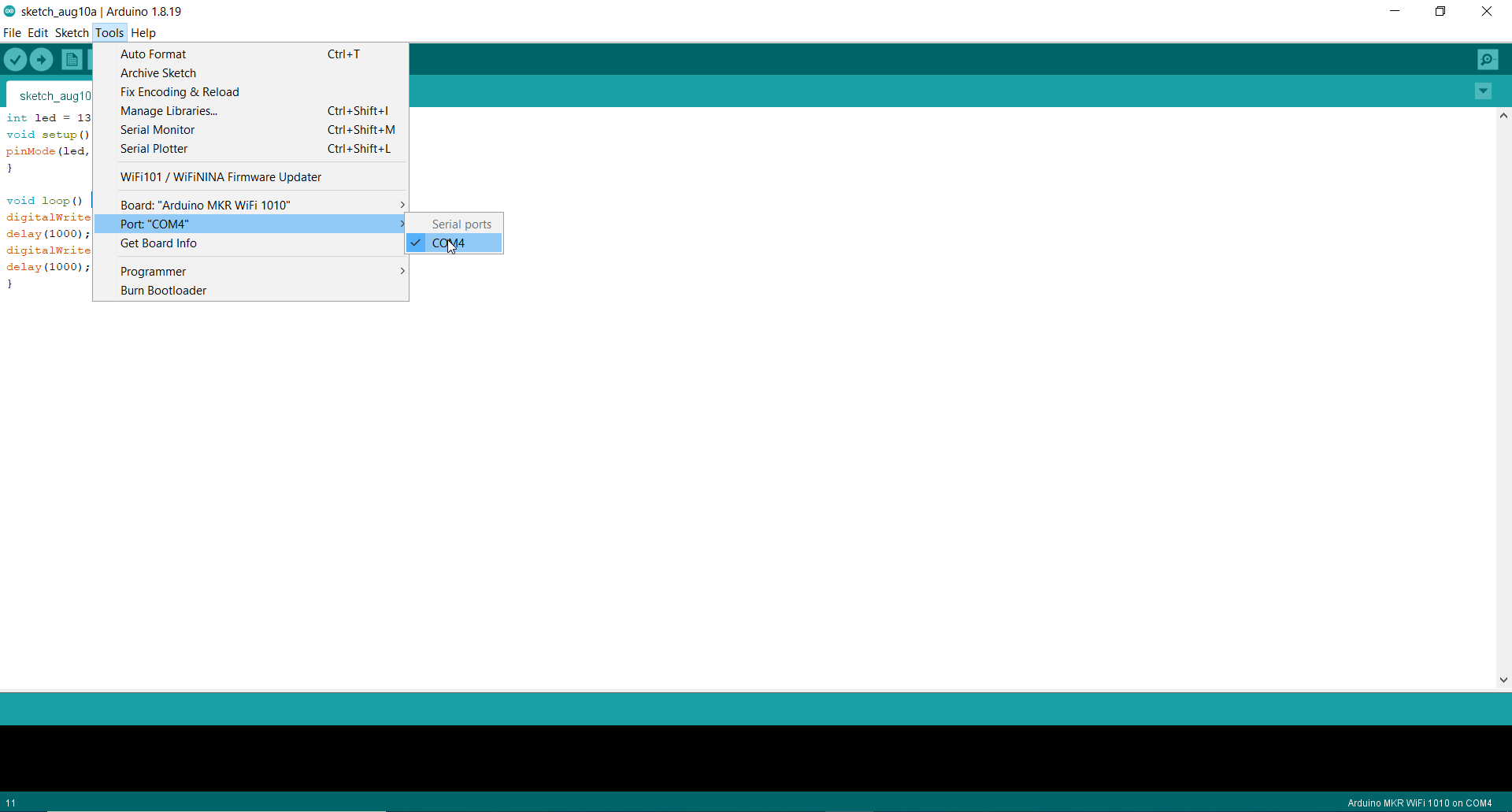
Then, go to Tools > Board and choose the one you are using. Next, go to Tools > Port and choose it’s port
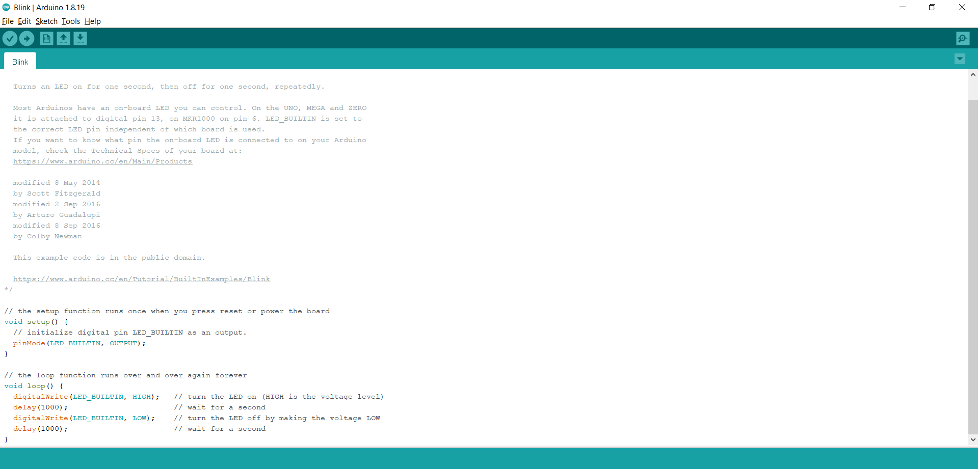
Task 1: The blinking
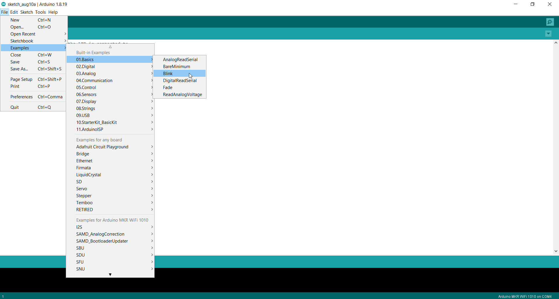
- First of all, go to File > Examples > 01.Basics > Blink. This code will makes the programable LED light (Orange) turn on for one second and off for one second repeatedly
/*
  Blink

  Turns an LED on for one second, then off for one second, repeatedly.

  Most Arduinos have an on-board LED you can control. On the UNO, MEGA and ZERO
  it is attached to digital pin 13, on MKR1000 on pin 6. LED_BUILTIN is set to
  the correct LED pin independent of which board is used.
  If you want to know what pin the on-board LED is connected to on your Arduino
  model, check the Technical Specs of your board at:
  https://www.arduino.cc/en/Main/Products

  modified 8 May 2014
  by Scott Fitzgerald
  modified 2 Sep 2016
  by Arturo Guadalupi
  modified 8 Sep 2016
  by Colby Newman

  This example code is in the public domain.

  https://www.arduino.cc/en/Tutorial/BuiltInExamples/Blink
*/

// the setup function runs once when you press reset or power the board
void setup() {
  // initialize digital pin LED_BUILTIN as an output.
  pinMode(LED_BUILTIN, OUTPUT);
}

// the loop function runs over and over again forever
void loop() {
  digitalWrite(LED_BUILTIN, HIGH);   // turn the LED on (HIGH is the voltage level)
  delay(1000);                       // wait for a second
  digitalWrite(LED_BUILTIN, LOW);    // turn the LED off by making the voltage LOW
  delay(1000);                       // wait for a second
}
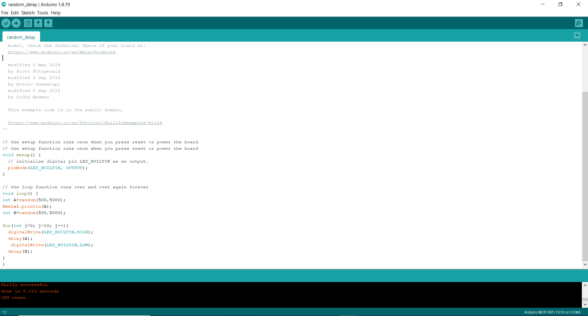
Task 2: Random delay
- Using the function random delay, I tried turning on the light for a random duration of time
/*
  Blink

  Turns an LED on for one second, then off for one second, repeatedly.

  Most Arduinos have an on-board LED you can control. On the UNO, MEGA and ZERO
  it is attached to digital pin 13, on MKR1000 on pin 6. LED_BUILTIN is set to
  the correct LED pin independent of which board is used.
  If you want to know what pin the on-board LED is connected to on your Arduino
  model, check the Technical Specs of your board at:
  https://www.arduino.cc/en/Main/Products

  modified 8 May 2014
  by Scott Fitzgerald
  modified 2 Sep 2016
  by Arturo Guadalupi
  modified 8 Sep 2016
  by Colby Newman

  This example code is in the public domain.

  https://www.arduino.cc/en/Tutorial/BuiltInExamples/Blink
*/

// the setup function runs once when you press reset or power the board
// the setup function runs once when you press reset or power the board
void setup() {
  // initialize digital pin LED_BUILTIN as an output.
  pinMode(LED_BUILTIN, OUTPUT);
}

// the loop function runs over and over again forever
void loop() {
int A=random(500,5000);
Serial.println(A);
int B=random(500,5000);

for(int j=0; j<10; j++){
  digitalWrite(LED_BUILTIN,HIGH);
  delay(A);
   digitalWrite(LED_BUILTIN,LOW);
  delay(B);
}
}
Task 3: Morse code
- I used morse code to make the light turn on and off spelling “Milan”. Using this link Morse code it will help you to convert any word into morse code.
Hint:
-
dot = 0.5 second light on, 0.5 second light off
-
dash =1.5 second light on, 0.5 second light off
-
Space = 0 second light on, 2.5 second light off
// the setup function runs once when you press reset or power the board
void setup() {
  // initialize digital pin LED_BUILTIN as an output.
  pinMode(LED_BUILTIN, OUTPUT);
}

// the loop function runs over and over again forever
void loop() {
 digitalWrite(LED_BUILTIN, HIGH);   // turn the LED on (HIGH is the voltage level)
  delay(1500);                       // wait for a second
  digitalWrite(LED_BUILTIN, LOW);    // turn the LED off by making the voltage LOW
  delay(500);                       // wait for a second
digitalWrite(LED_BUILTIN, HIGH);   // turn the LED on (HIGH is the voltage level)
  delay(1500);                       // wait for a second
  digitalWrite(LED_BUILTIN, LOW);    // turn the LED off by making the voltage LOW
  delay(500);                       // wait for a second


  digitalWrite(LED_BUILTIN, HIGH);   // turn the LED on (HIGH is the voltage level)
  delay(0);                       // wait for a second
  digitalWrite(LED_BUILTIN, LOW);    // turn the LED off by making the voltage LOW
  delay(2500);                       // wait for a second

digitalWrite(LED_BUILTIN, HIGH);   // turn the LED on (HIGH is the voltage level)
  delay(500);                       // wait for a second
  digitalWrite(LED_BUILTIN, LOW);    // turn the LED off by making the voltage LOW
  delay(500);                       // wait for a second
  digitalWrite(LED_BUILTIN, HIGH);   // turn the LED on (HIGH is the voltage level)
  delay(500);                       // wait for a second
  digitalWrite(LED_BUILTIN, LOW);    // turn the LED off by making the voltage LOW
  delay(500);                       // wait for a second


digitalWrite(LED_BUILTIN, HIGH);   // turn the LED on (HIGH is the voltage level)
  delay(0);                       // wait for a second
  digitalWrite(LED_BUILTIN, LOW);    // turn the LED off by making the voltage LOW
  delay(2500);                       // wait for a second

  digitalWrite(LED_BUILTIN, HIGH);   // turn the LED on (HIGH is the voltage level)
  delay(500);                       // wait for a second
  digitalWrite(LED_BUILTIN, LOW);    // turn the LED off by making the voltage LOW
  delay(500);                       // wait for a second
  digitalWrite(LED_BUILTIN, HIGH);   // turn the LED on (HIGH is the voltage level)
  delay(1500);                       // wait for a second
  digitalWrite(LED_BUILTIN, LOW);    // turn the LED off by making the voltage LOW
  delay(500);                       // wait for a second
digitalWrite(LED_BUILTIN, HIGH);   // turn the LED on (HIGH is the voltage level)
  delay(500);                       // wait for a second
  digitalWrite(LED_BUILTIN, LOW);    // turn the LED off by making the voltage LOW
  delay(500);                       // wait for a second
  digitalWrite(LED_BUILTIN, HIGH);   // turn the LED on (HIGH is the voltage level)
  delay(500);                       // wait for a second
  digitalWrite(LED_BUILTIN, LOW);    // turn the LED off by making the voltage LOW
  delay(500);                       // wait for a second

  digitalWrite(LED_BUILTIN, HIGH);   // turn the LED on (HIGH is the voltage level)
  delay(0);                       // wait for a second
  digitalWrite(LED_BUILTIN, LOW);    // turn the LED off by making the voltage LOW
  delay(2500);                       // wait for a second

digitalWrite(LED_BUILTIN, HIGH);   // turn the LED on (HIGH is the voltage level)
  delay(500);                       // wait for a second
  digitalWrite(LED_BUILTIN, LOW);    // turn the LED off by making the voltage LOW
  delay(500);                       // wait for a second
digitalWrite(LED_BUILTIN, HIGH);   // turn the LED on (HIGH is the voltage level)
  delay(1500);                       // wait for a second
  digitalWrite(LED_BUILTIN, LOW);    // turn the LED off by making the voltage LOW
  delay(500);                       // wait for a second

  digitalWrite(LED_BUILTIN, HIGH);   // turn the LED on (HIGH is the voltage level)
  delay(0);                       // wait for a second
  digitalWrite(LED_BUILTIN, LOW);    // turn the LED off by making the voltage LOW
  delay(2500);                       // wait for a second

  digitalWrite(LED_BUILTIN, HIGH);   // turn the LED on (HIGH is the voltage level)
  delay(1500);                       // wait for a second
  digitalWrite(LED_BUILTIN, LOW);    // turn the LED off by making the voltage LOW
  delay(500);                       // wait for a second
  digitalWrite(LED_BUILTIN, HIGH);   // turn the LED on (HIGH is the voltage level)
  delay(500);                       // wait for a second
  digitalWrite(LED_BUILTIN, LOW);    // turn the LED off by making the voltage LOW
  delay(500);                       // wait for a second

   digitalWrite(LED_BUILTIN, LOW);    // turn the LED off by making the voltage LOW
  delay(2500);                       // wait for a second


}
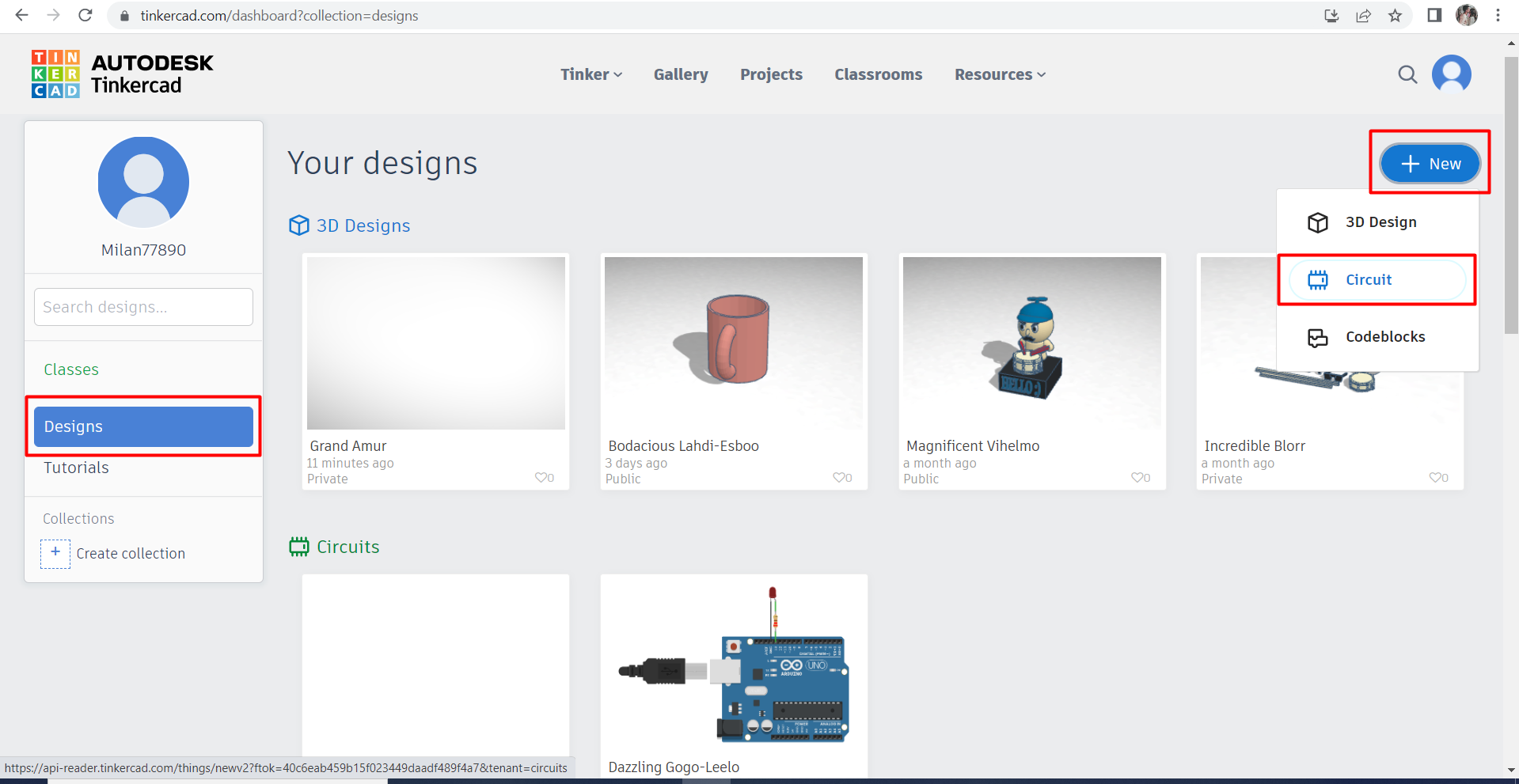
Task 4: Trying another programming environment
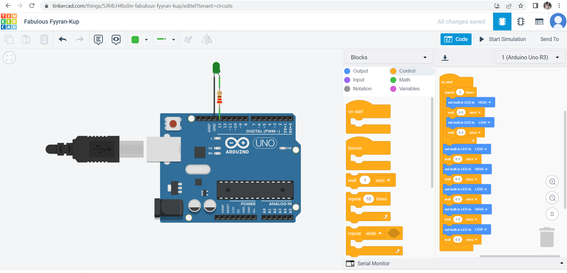
For this task, I used Tinkercad which is another software to code microcontrollers and it is similar to Arduino.
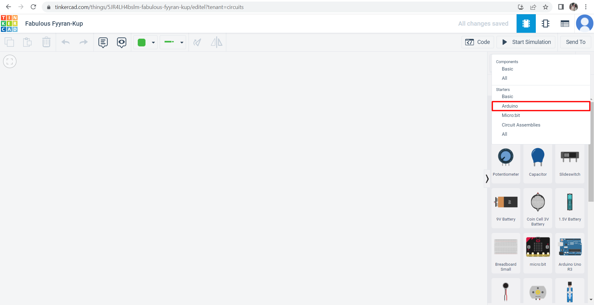
- First, open the website from here Tinkercad. Then, to start designing press on designs > new > circuit.
- After that, press on the component to open the list and choose Arduino
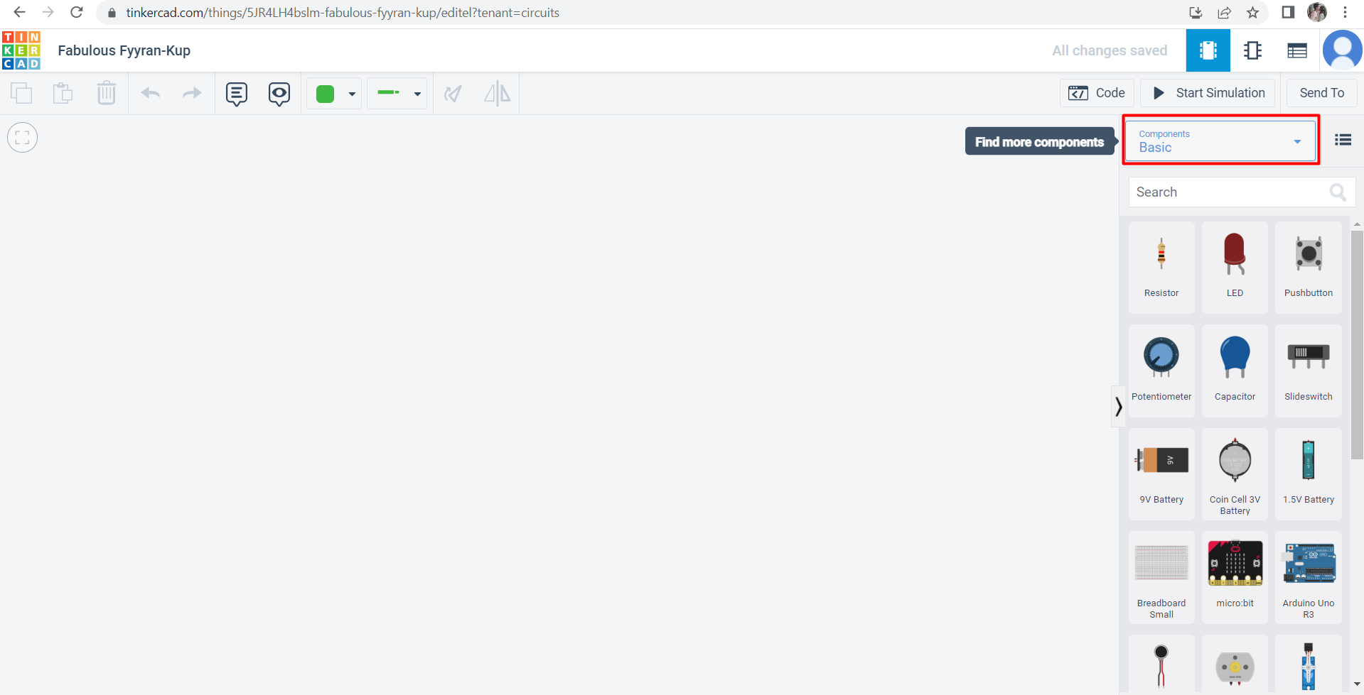
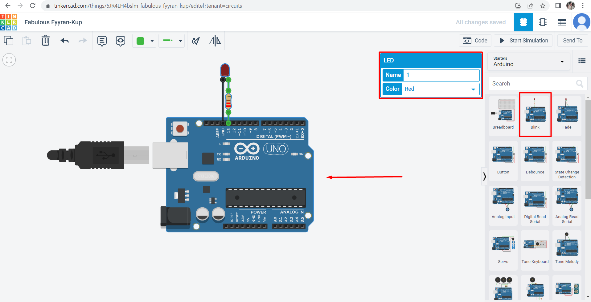
- Next, you will find a lot of examples, I picked the blink example which I already did before while using the Arduino Software (IDE). Additionally, you can change the color of the LED so I chose the green color.
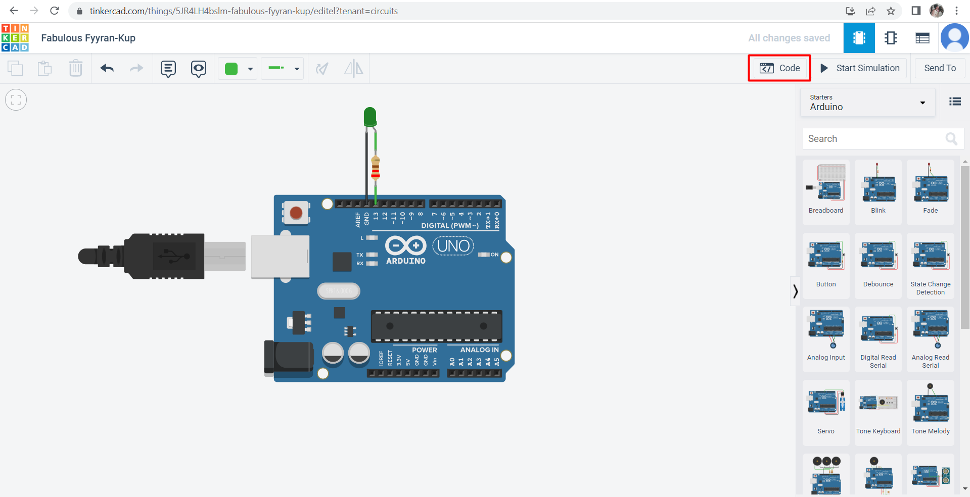
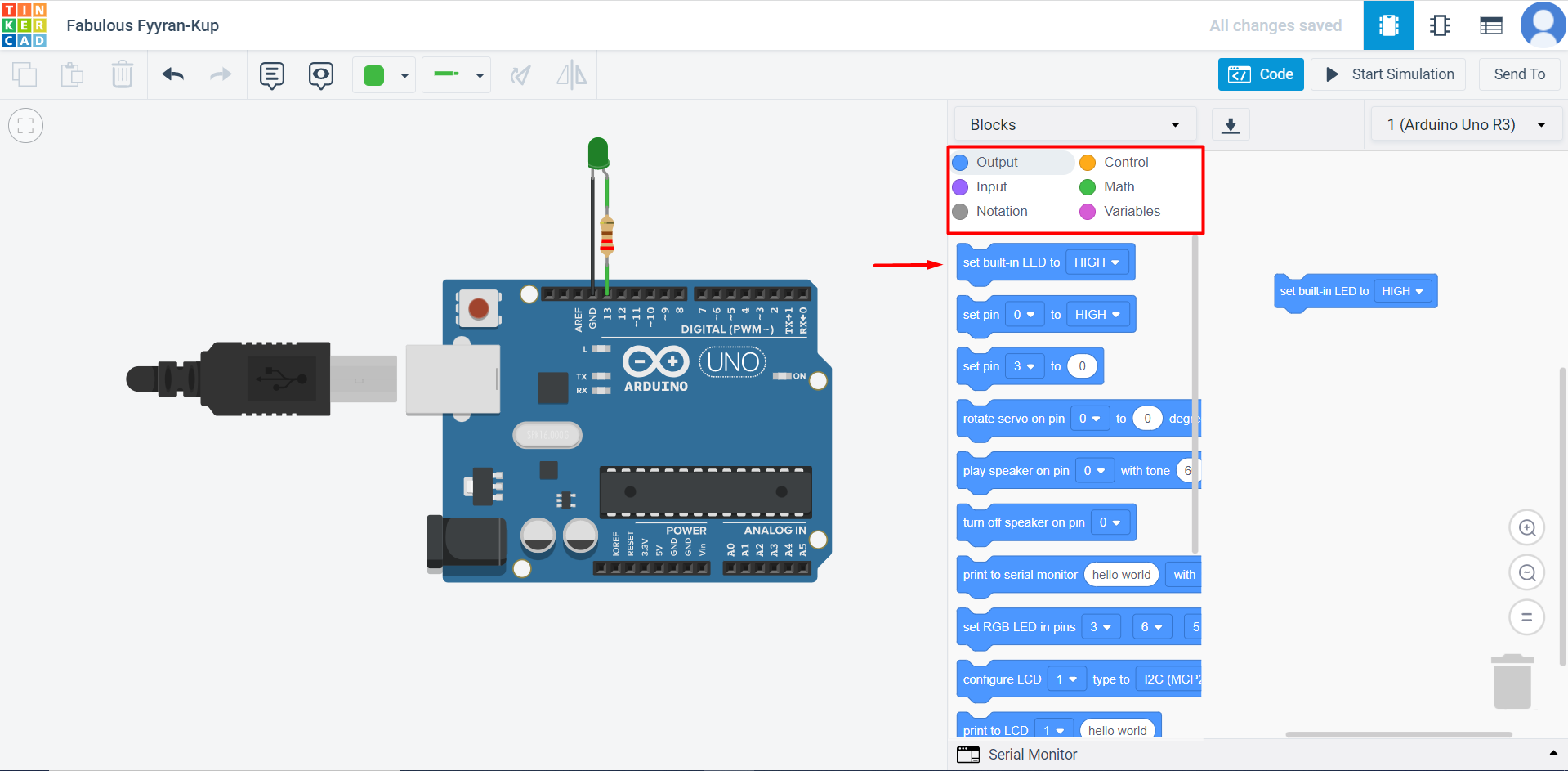
- To start coding, press on code to open the list for coding and choose the blocks.
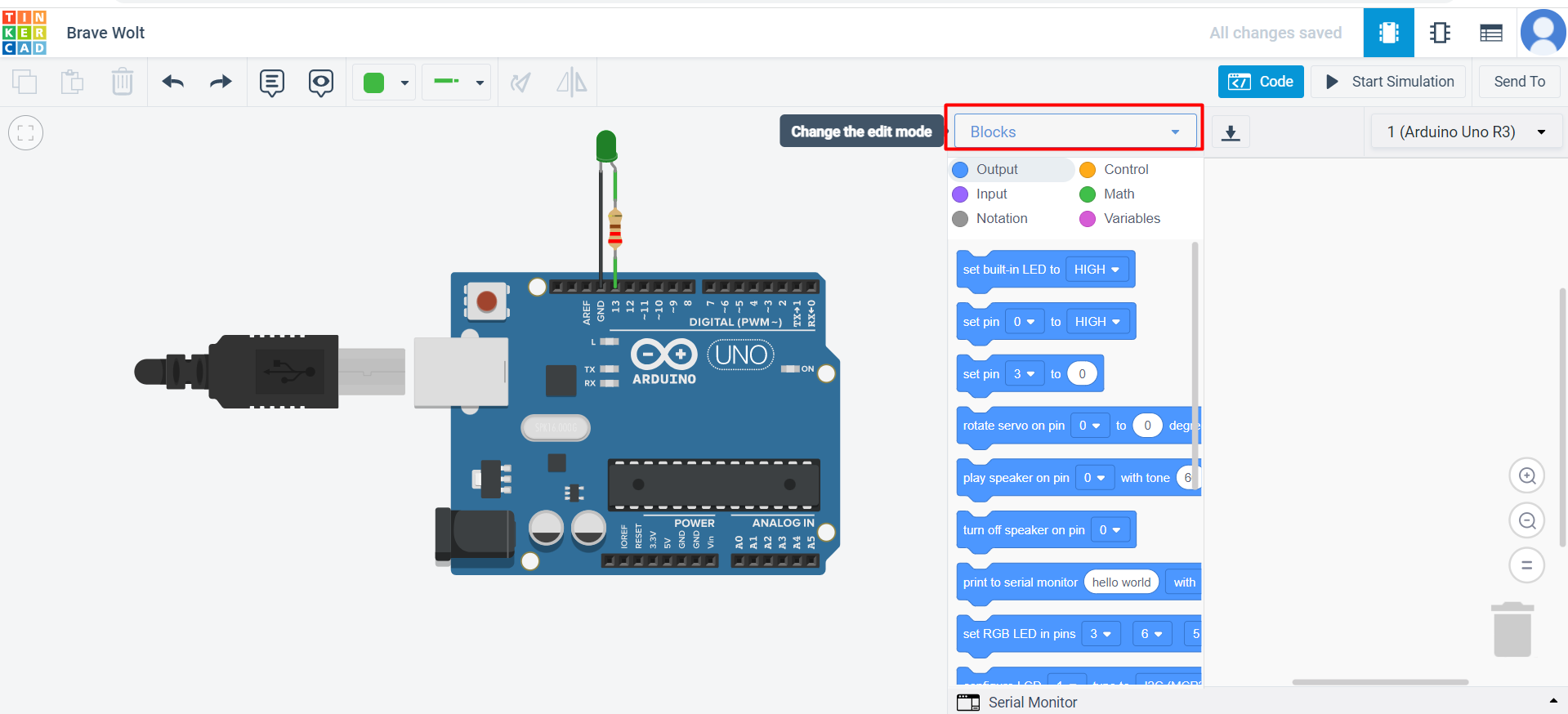
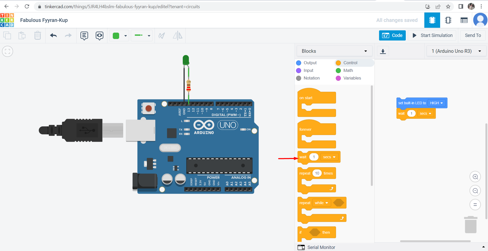
- I tried first to do the simple task which is the blinking and I used the output as well as the control to create the code.
- Then, I clicked on “start simulation” to view the outcome.
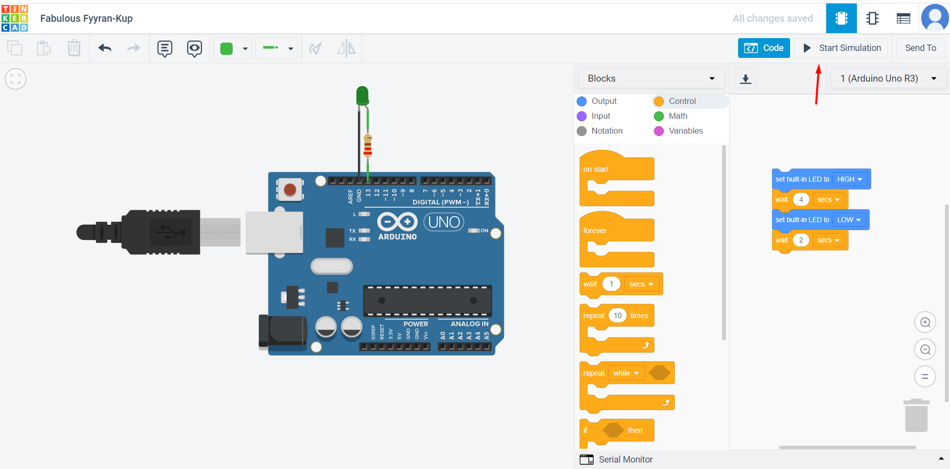
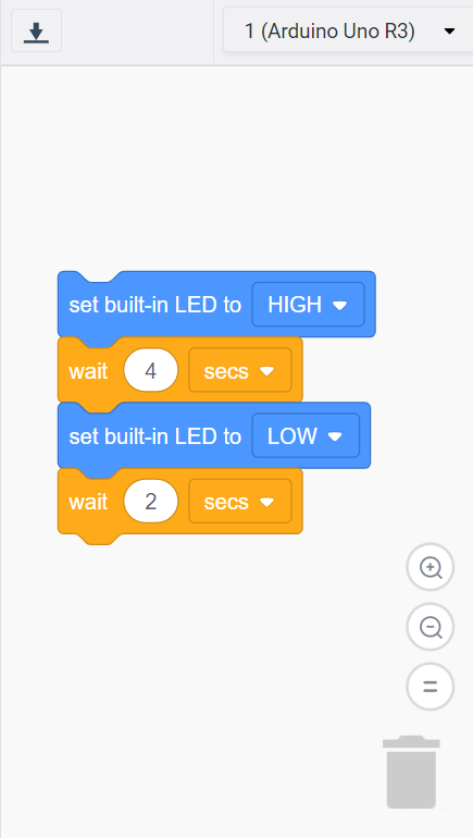
The result
Hint: It should blink for 4 seconds, turn off for 2, then repeat this cycle till I stop the simulation.
- After that, I used morse code to make the light turn on and off spelling the first two letters of my name which are “SA”. Using this link Morse code it will help you to convert any word into morse code.
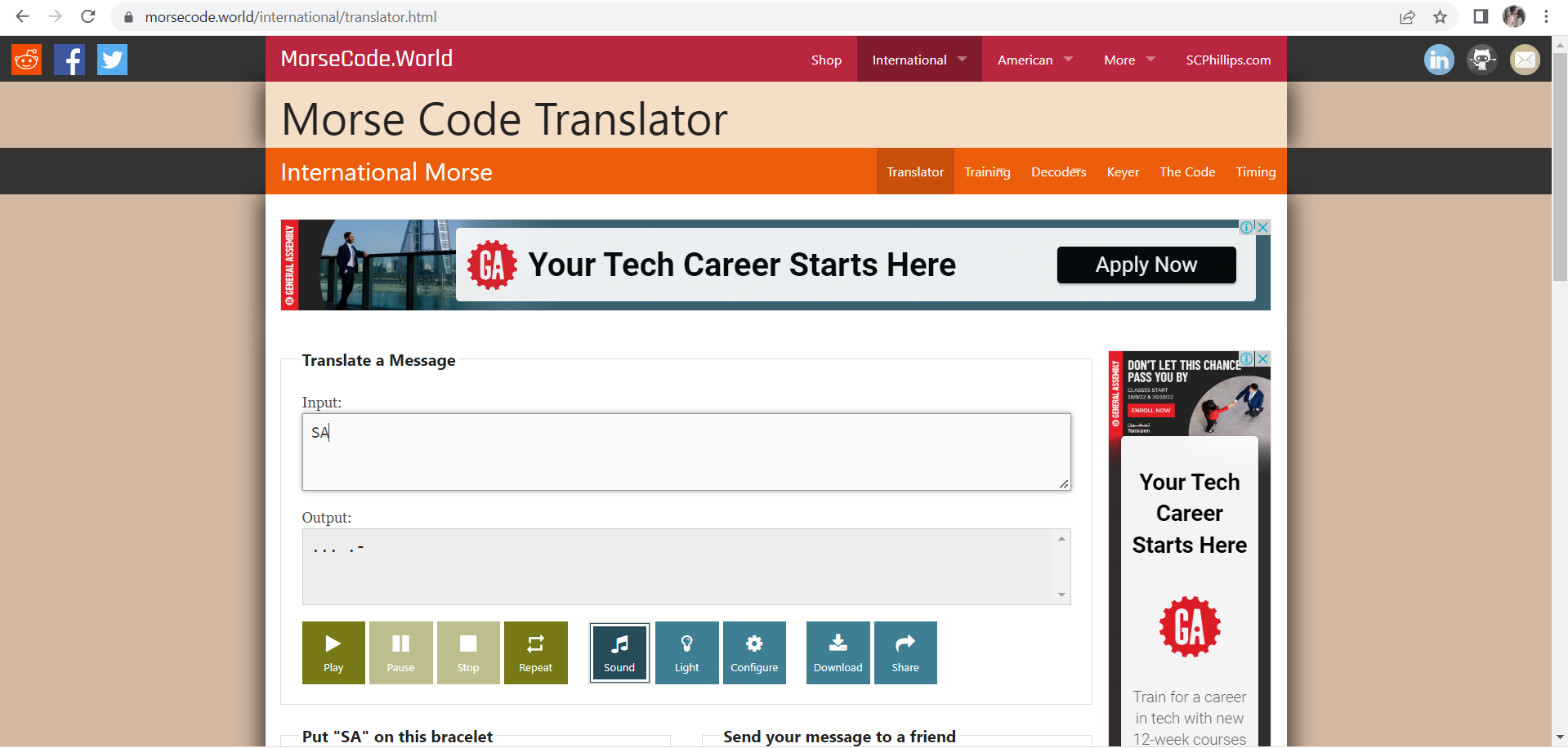
Hint:
-
dot = 0.5 second light on, 0.5 second light off
-
dash =1.5 second light on, 0.5 second light off
-
Space = 0 second light on, 0.5 second light off
-
This is the code that I created.
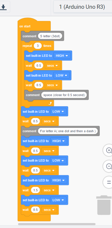
- The final result