7. Input & Output device
This week, I focused on output devices and input sensors that were attached to the Arduino MKR WIFI 1010 microcontroller.
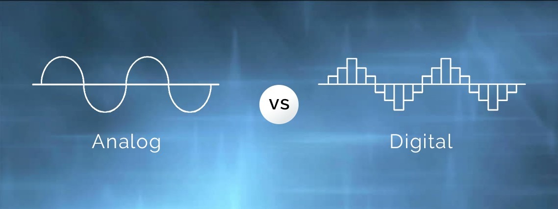
Analog & Digital Signal
Signal: A signal is an electromagnetic or electrical current that is used for carrying data from one system or network to another. In electronics and telecommunications, it refers to any time-varying voltage that is an electromagnetic wave which carries information. There are two main types of signals which are Analog signal and Digital signal.
Analog Signal: Is a continuous signal where one temporally varying quantity stands in for another temporally based variable. These signals depend on physical parameters and natural occurrences like earthquakes, frequency, volcanoes, wind speed, weight, and lighting, among others.
Digital Signal: Is a signal that is used to represent data as a series of distinct values at each given time. It can only take on one of a fixed number of values. Within a fixed range of values, this kind of signal denotes a real number.
Characteristics of Analog Signal:
- These electronic signals change throughout time.
- Minimum and maximum values which is either positive or negative.
- It operates with continuous data.
- Either periodic or nonperiodic behavior is possible.
- It aids in measuring physical or natural values.
Characteristics of Digital Signals:
- Digital signals are time separated signals.
- Due to their flexibility, digital signals are frequently used.
- It has better accuracy than that of the analog signal.
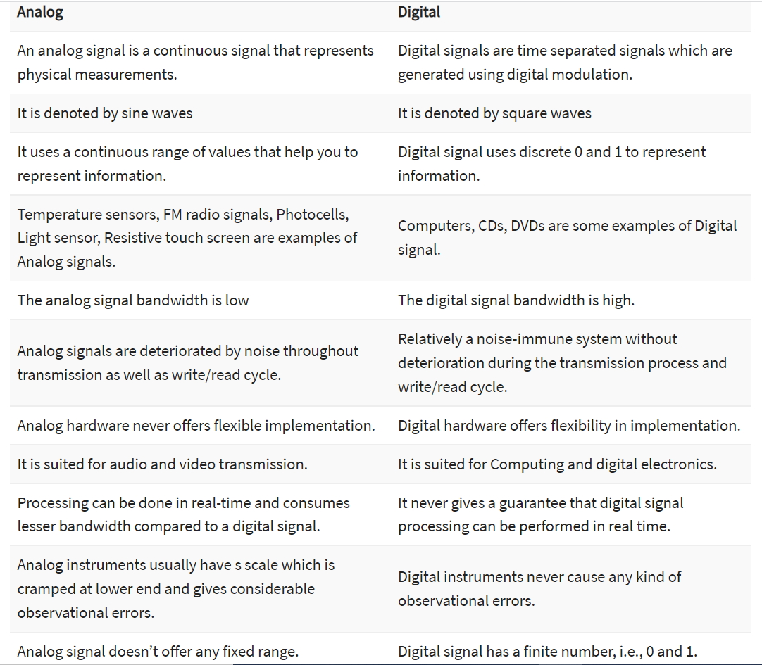
The Difference Between Analog and Digital Signal:
Advantages of Analog Signals:
- Most suited for transmitting audio and video.
- It is portable and inexpensive.
- It presents more precise information because of its significantly higher density.
- It is the natural form of a sound and it can more accurately depict a sound.
Disadvantages of Analog Signals:
- Compared to digital, it has a signal of inferior quality.
- The cables are vulnerable to outside effects.
- Analog wire is expensive and difficult to transport.
- Offers poor multi-user interfaces.
- Data can become corrupted.
Advantages of Digital Signals:
- Its data is simple to compress.
- Digital signal-using equipment is more accessible and less expensive.
- Data transmission through networks is simple.
- Without changing the original file, the sound can be edited.
Disadvantages of Digital Signals:
- Sampling may cause loss of information.
- Limited processor speed.
- There are more complicated systems and processes.
- It requires greater bandwidth.
Task 1
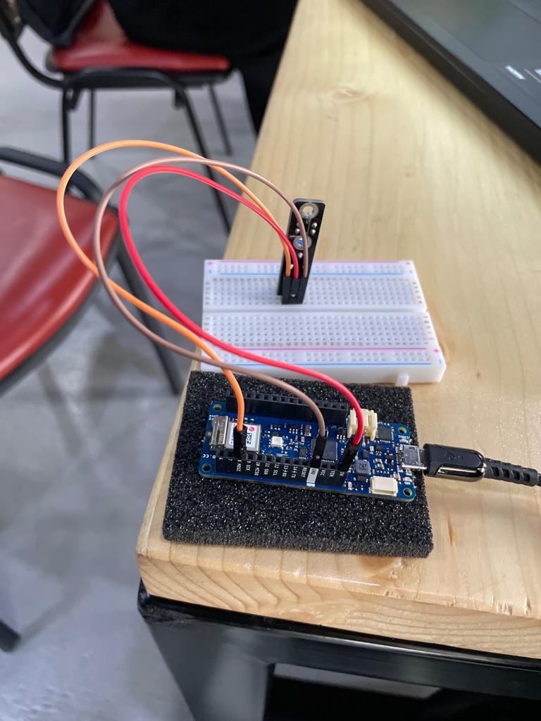
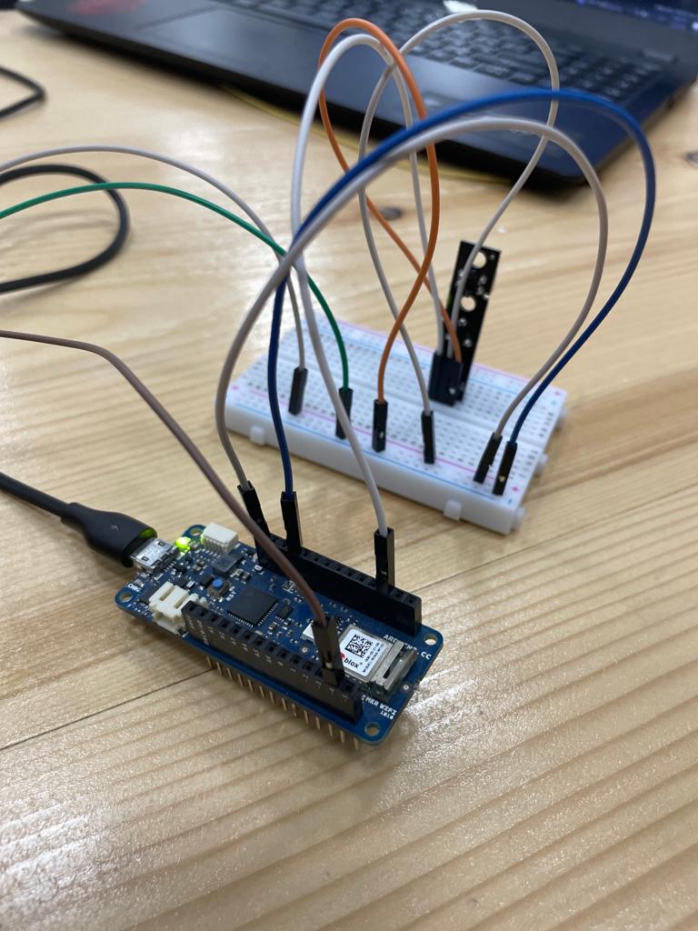
Arduino MKR WIFI 1010 has a lot of sensors and the one I tried was the tracking sensor. So, I started with connecting the sensor with the microcontroller using Arduino as it shown in the image.
Tracking Sensor: The line tracking sensor works by detecting reflected light coming from its own infrared LED and by measuring the amount of reflected infrared light, it can detect transitions from light to dark (lines) or even objects directly in front of it.
![]()
Features:
-
sensor adopts TCRT5000, high sensitivity.
-
sensitivity adjustable by potentiometer.
-
working voltage: 3.3V – 5V.
-
operating current: 20mA.
-
digital switch output (0 and 1).
-
has 2 fixed bolt holes, convenient installation.
-
small board PCB size: 42 x 10.5 mm.
-
power indicator light (red) and digital switch output indicator light (green).
-
detection reflection distance: 1 mm – 25 mm.
Hint:
- The red wire is connected to the 5V.
- The orange wire is connected to pin 8.
- The last wire is connected to the GND.
- I used the following code for the tracking sensor.
#define sensor 2
#define buzzer 3
#define red 4
#define green 5
int pot = 8;
void setup() {
Serial.begin(9600);
pinMode(sensor,INPUT);
pinMode(buzzer,OUTPUT);
pinMode(green,OUTPUT);
pinMode(red,OUTPUT);
Serial.begin(9600);

}

void loop() {
bool value = digitalRead(sensor);
if(value == 0)
{
  digitalWrite(buzzer, HIGH);
    digitalWrite(green, HIGH);
      digitalWrite(red, HIGH);

}
else
{
    digitalWrite(buzzer, LOW);
    digitalWrite(green, LOW);
      digitalWrite(red, LOW);
  }
Serial.print(digitalRead(8));
delay(500);
}
Video
Hint : As we can see from the video, as soon we place our hand in front of the tracking sensor, the sensor will detect our hand and give us the value zero in the serial monitor. So, it’s sensing our hand from the physical world and conver it to a value which is zero in this case in the digital world.
Task 2
After being done from the tracking sensor, now testing the servo motor as an output device.
-
First, starting with the wire connections, the servo motor has three wires connect to the Arduino, the red wire is connected to the 5V, the orange wire is connected to pin 9 and the last wire is connected to the GND.
-
I tried the sweep example so to get the code for it, go to file > Examples > servo > sweep.
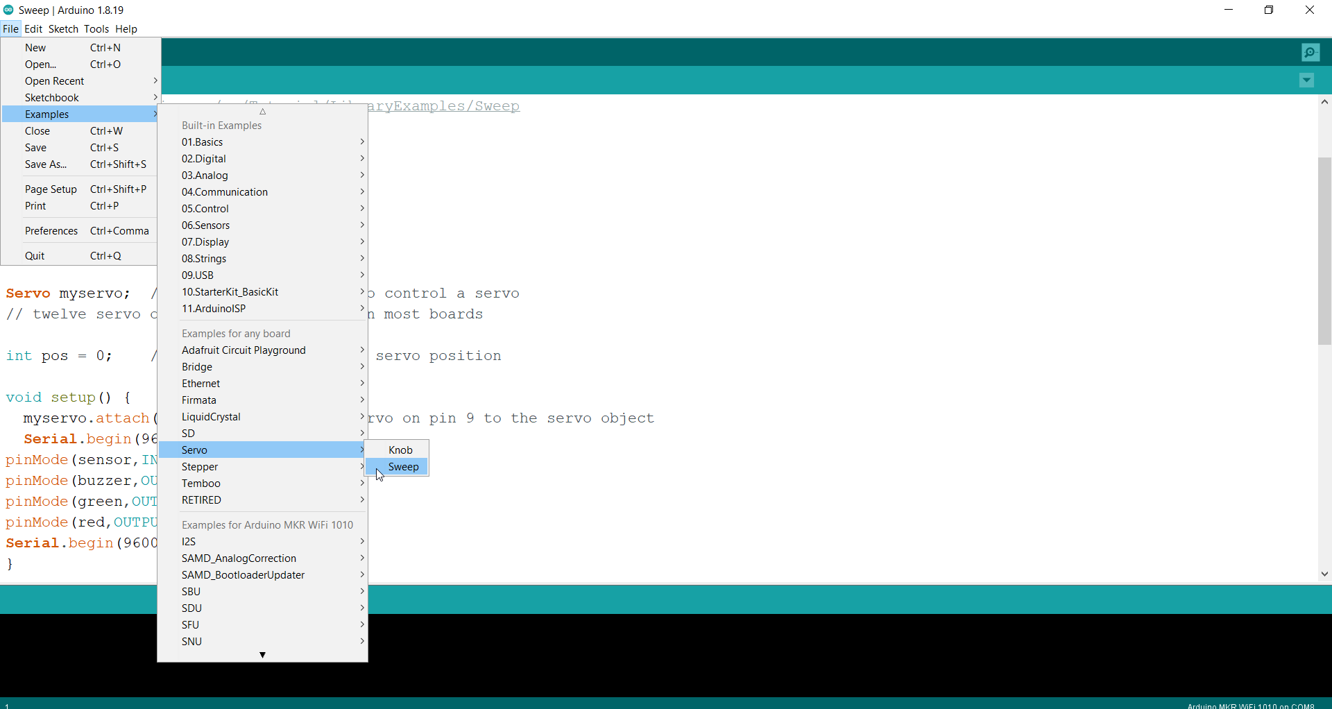
The sweep code:
/* Sweep
 by BARRAGAN <http://barraganstudio.com>
 This example code is in the public domain.

 modified 8 Nov 2013
 by Scott Fitzgerald
 https://www.arduino.cc/en/Tutorial/LibraryExamples/Sweep
*/

#include <Servo.h>

Servo myservo;  // create servo object to control a servo
// twelve servo objects can be created on most boards

int pos = 0;    // variable to store the servo position

void setup() {
  myservo.attach(9);  // attaches the servo on pin 9 to the servo object
}

void loop() {
  for (pos = 0; pos <= 180; pos += 1) { // goes from 0 degrees to 180 degrees
    // in steps of 1 degree
    myservo.write(pos);              // tell servo to go to position in variable 'pos'
    delay(15);                       // waits 15 ms for the servo to reach the position
  }
  for (pos = 180; pos >= 0; pos -= 1) { // goes from 180 degrees to 0 degrees
    myservo.write(pos);              // tell servo to go to position in variable 'pos'
    delay(15);                       // waits 15 ms for the servo to reach the position
  }
}
Video
Hint: A Servo Motor is a small device that has an output shaft. This shaft can be positioned to specific angular positions by sending the servo a coded signal. As long as the coded signal exists on the input line, the servo will maintain the angular position of the shaft. So, the code from the digital world will let the motor start rotating 180 degrees in the physical world.
Task 3
Connecting a microcontroller with an input and output devices.
Hanaa, a colleague of mine, and I made the decision to use the tracking sensor as an input device and the servo motor as an output device. How will it operate then? The servo motor will begin rotating 180 degrees when your hand is placed in front of the tracking sensor thanks to code we created using the Arduino Software (IDE).
- Here is the code we employed.
#include <Servo.h>

Servo myservo;  // create servo object to control a servo
// twelve servo objects can be created on most boards

int pos = 0;    // variable to store the servo position
#define sensor 2
#define buzzer 3
#define red 4
#define green 5
int pot = 8;
void setup() {
Serial.begin(9600);
pinMode(sensor,INPUT);
pinMode(buzzer,OUTPUT);
pinMode(green,OUTPUT);
pinMode(red,OUTPUT);
Serial.begin(9600);
myservo.attach(4);  // attaches the servo on pin 9 to the servo object
}

void loop() {
bool value = digitalRead(sensor);
if(value == 0)
{
  digitalWrite(buzzer, HIGH);
    digitalWrite(green, HIGH);
      digitalWrite(red, HIGH);
  for (pos = 0; pos <= 180; pos += 1) { // goes from 0 degrees to 180 degrees
    // in steps of 1 degree
    myservo.write(pos);              // tell servo to go to position in variable 'pos'
    delay(15);                       // waits 15 ms for the servo to reach the position
  }
  for (pos = 180; pos >= 0; pos -= 1) { // goes from 180 degrees to 0 degrees
    myservo.write(pos);              // tell servo to go to position in variable 'pos'
    delay(15);                       // waits 15 ms for the servo to reach the position
  }
}
else
{
    digitalWrite(buzzer, LOW);
    digitalWrite(green, LOW);
      digitalWrite(red, LOW);
  }
Serial.print(digitalRead(8));
delay(500);
}
- And this is the circuit that we utilized
- The result
Problems
The first two tasks I completed without any problems; however, task 3, which involved connecting a microcontroller to input and output devices, was problematic for me. I had a lot of difficulty completing the circuit for this task, but I eventually succeeded. I also encountered a problem with the if statement, which allows the motor to run when the tracking sensor detects our hand. So I looked up how to write an if statement on Google and was eventually successful.