6. Large format CNC (computer controlled Machining)
I worked on a group assignment this week that required testing runout, alignment, speeds, feeds, and toolpaths for the CNC machine, as well as an individual assignment that required designing a large object for the kids using the CNC machine to cut it out, and then assembling it.
CNC:
Computer Numerical Control (CNC) machining is a manufacturing process in which pre-programmed computer software dictates the movement of factory tools and machinery. The process can be used to control a range of complex machinery, from grinders and lathes to mills and CNC routers. With CNC machining, three-dimensional cutting tasks can be accomplished in a single set of prompts.
Group Assignment
In this group assignment, we’ll look at the process used to test the crucial factors affecting the operation of the CNC machine. For more informations, check out Hood Website.
Individual Assignment
Design
I wanted to create a game that kids might enjoy themselves playing, therefore I chose to create the foosball.
Designing the fooseball
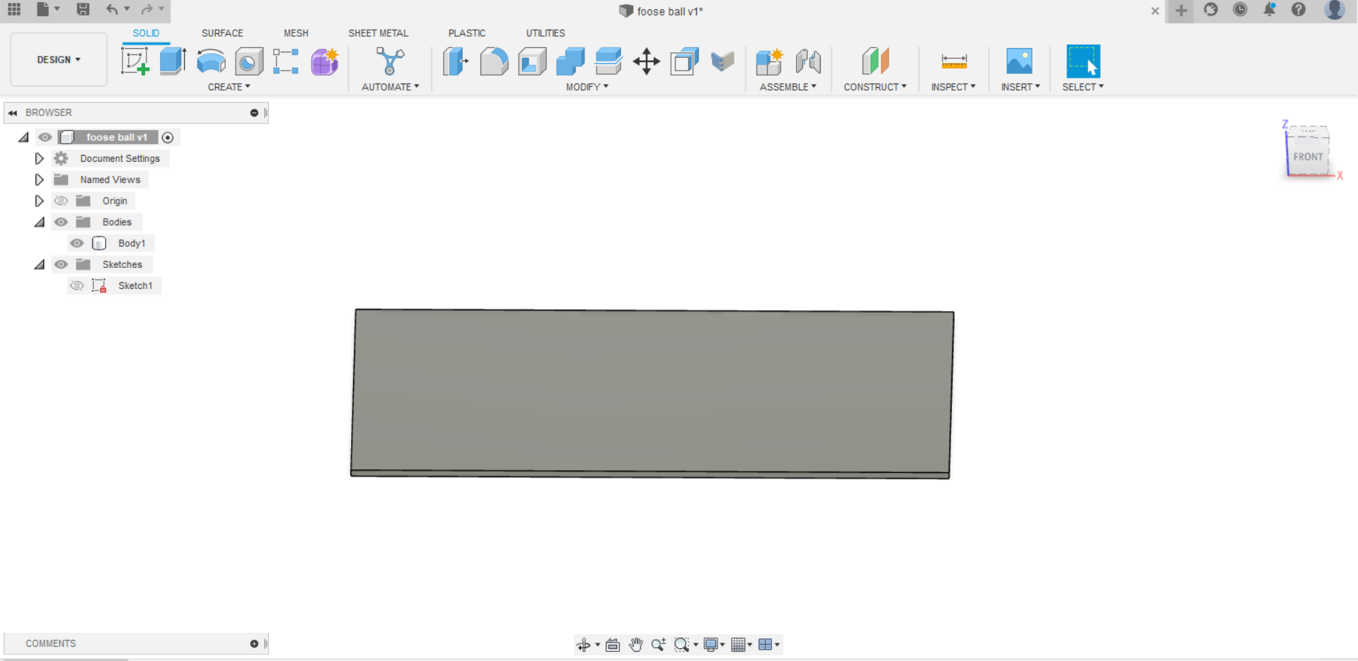
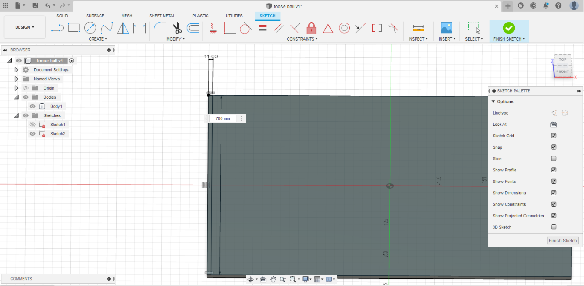
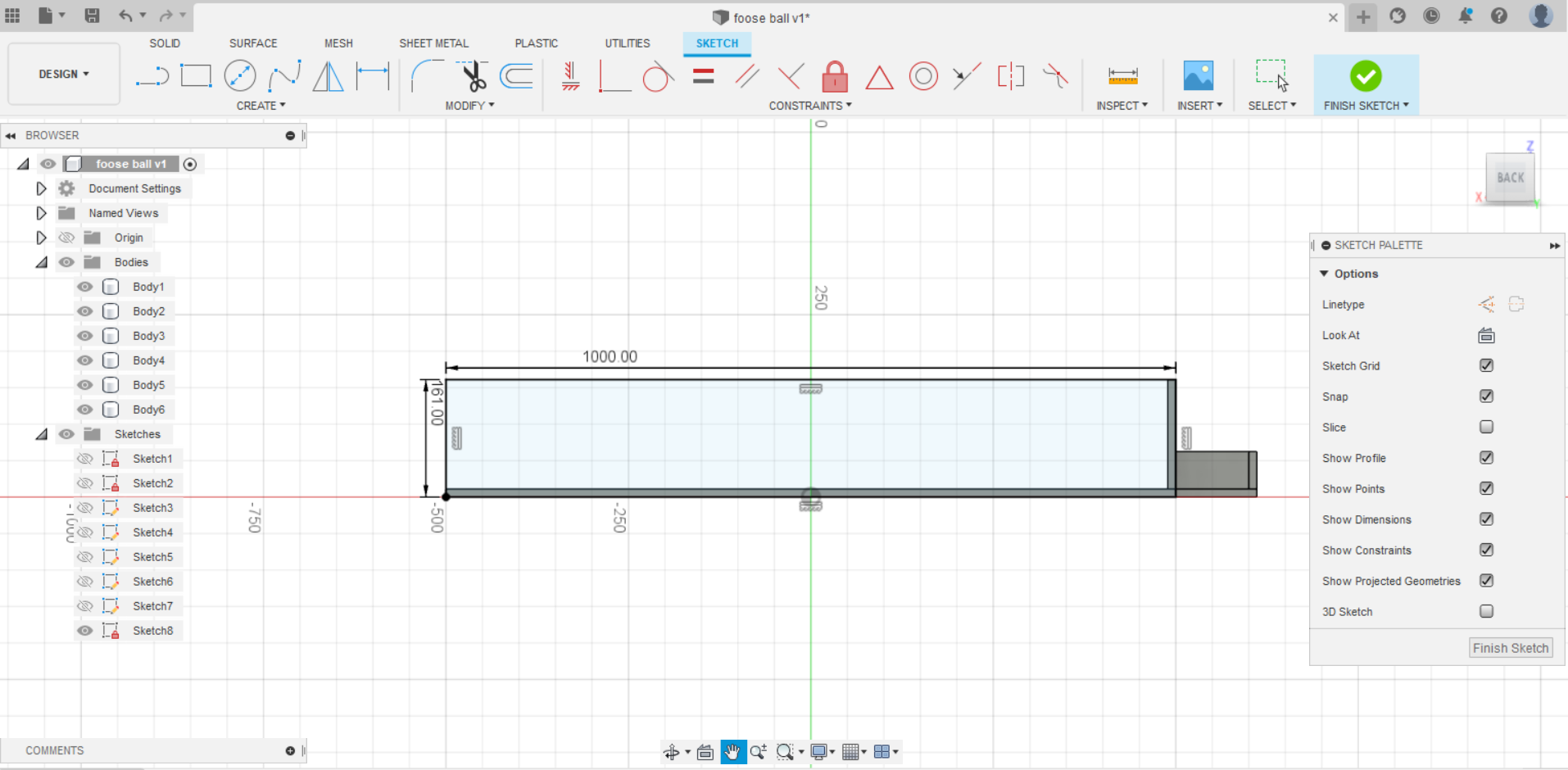
- I started with creating the base with a size of 1000 mm depth and 700 mm width.
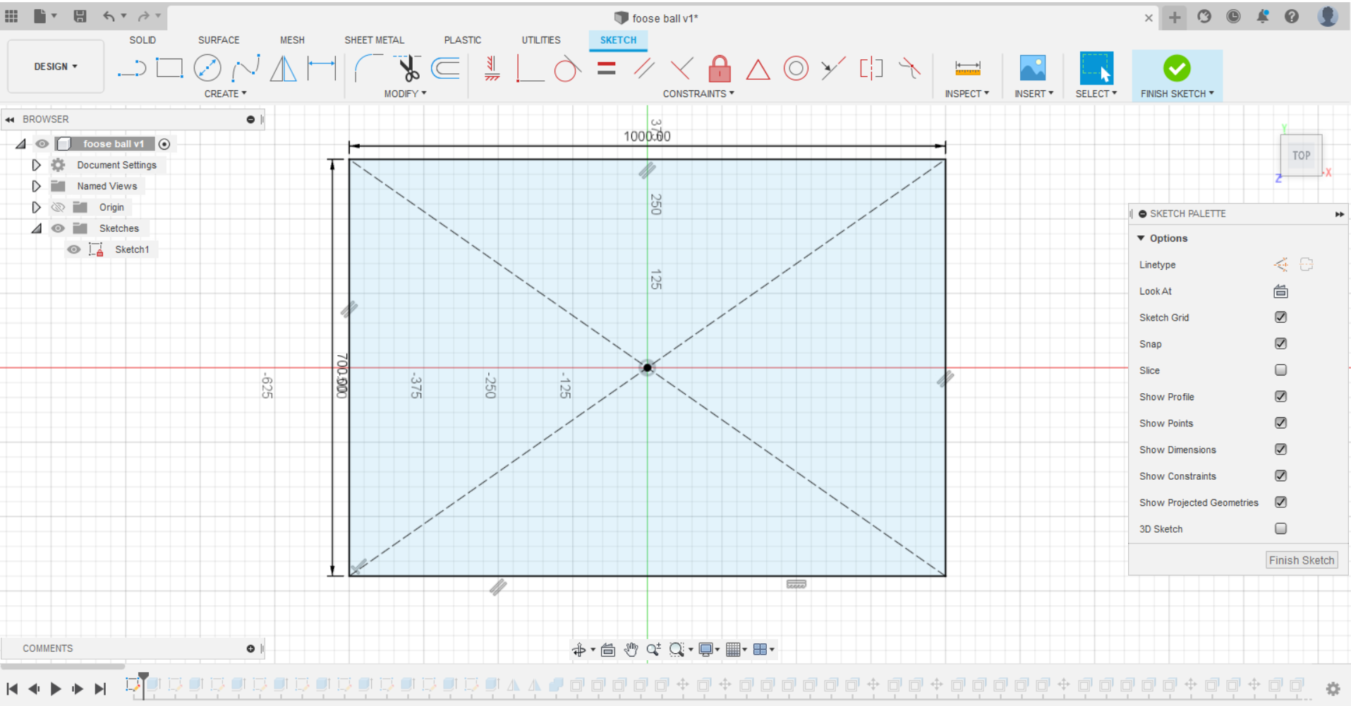
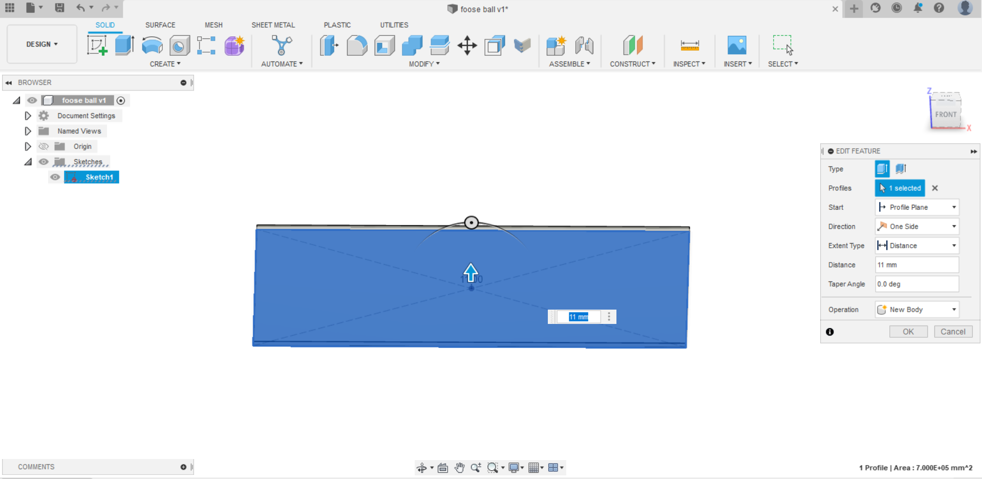
- Then, I extrude it with a thickness of 11 mm because MDF is the material that will be use for cutting.
Hint: Every part of the design was created with the thickness of 11 mm.
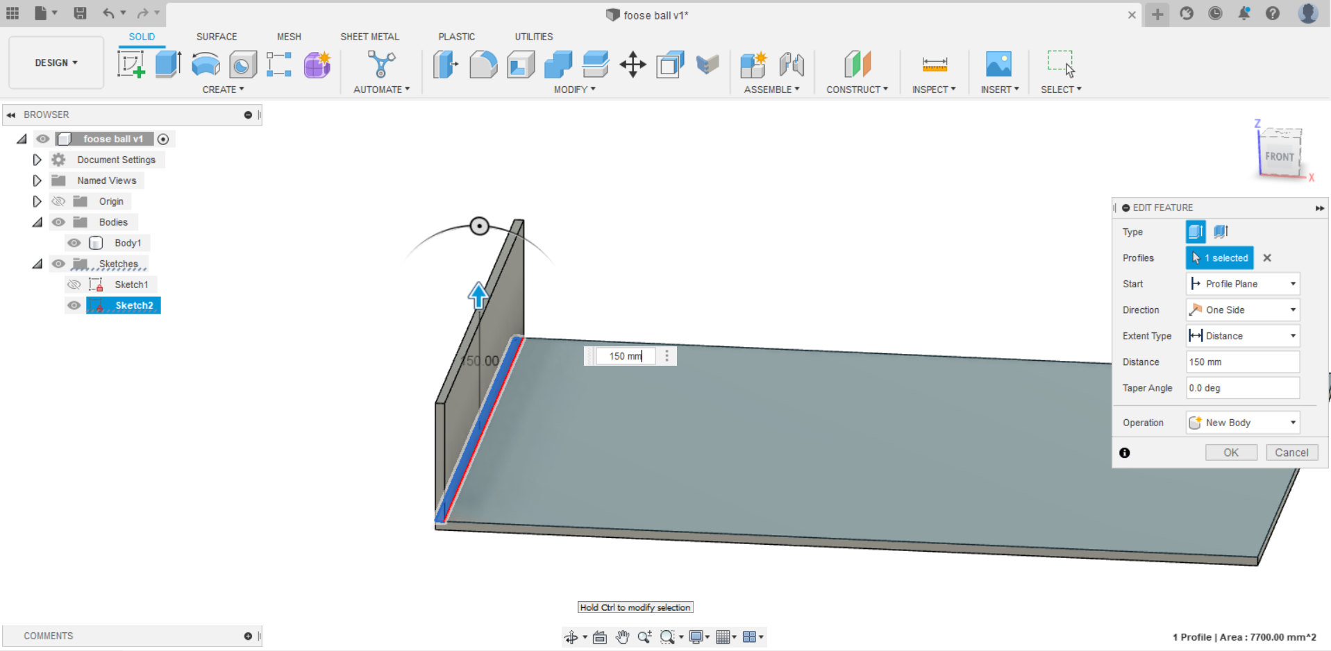
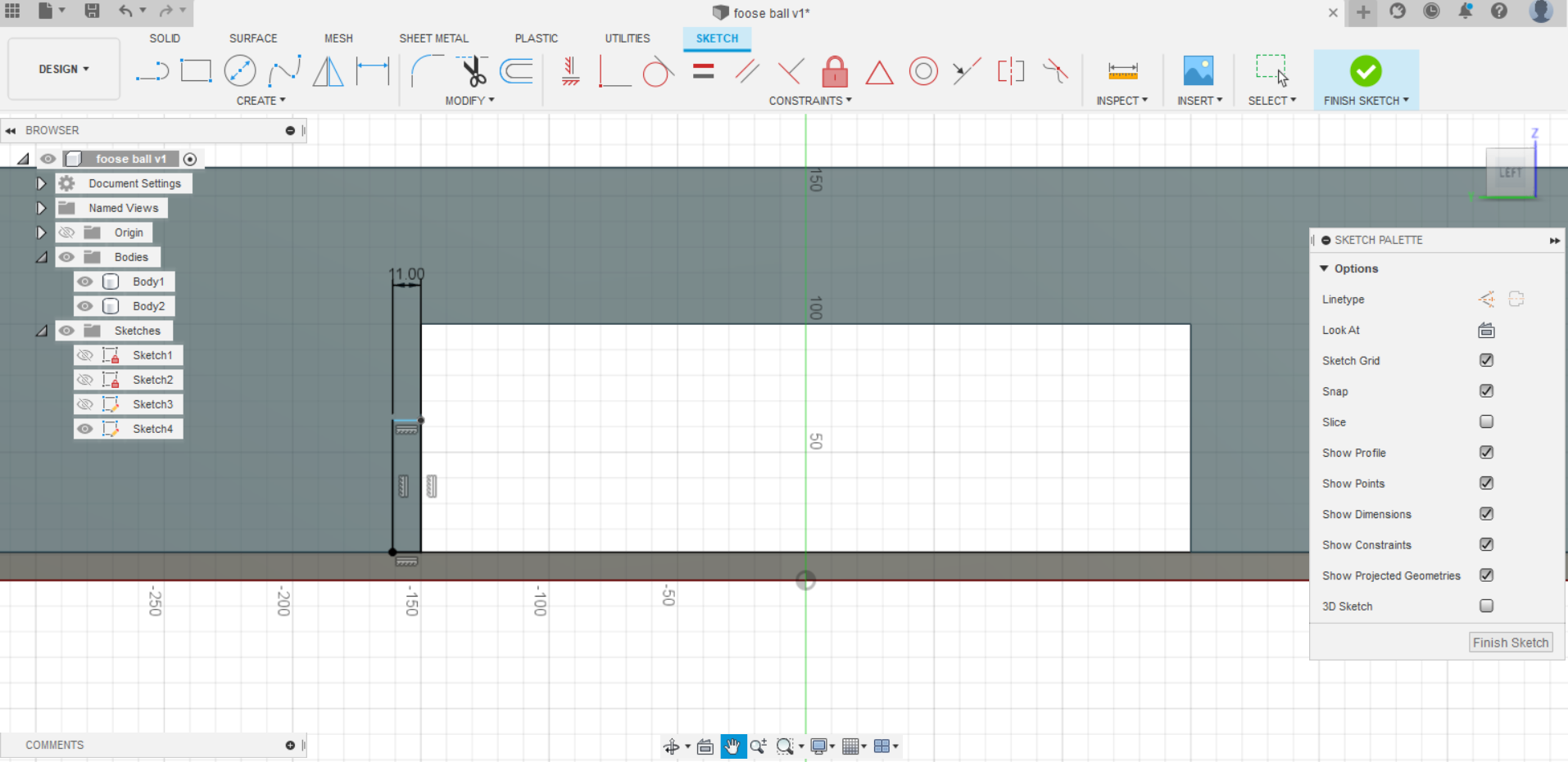
- After that, I added a new sketch on the base to create the wall of the front goal and it’s height was 150 mm.
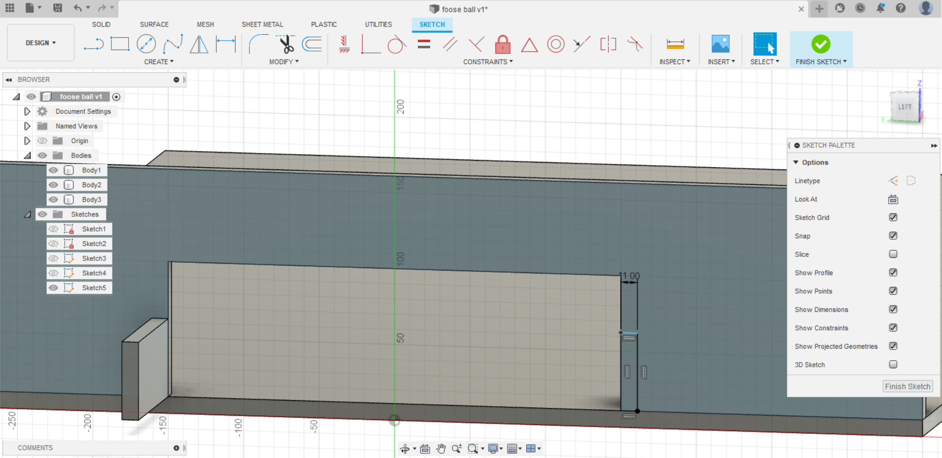
- Next, I added a sketch on the wall of the goal to draw the goal and unfill it. Also, I created several sketches on the same wall and one on front of the side wall after creating it to make the goal block.
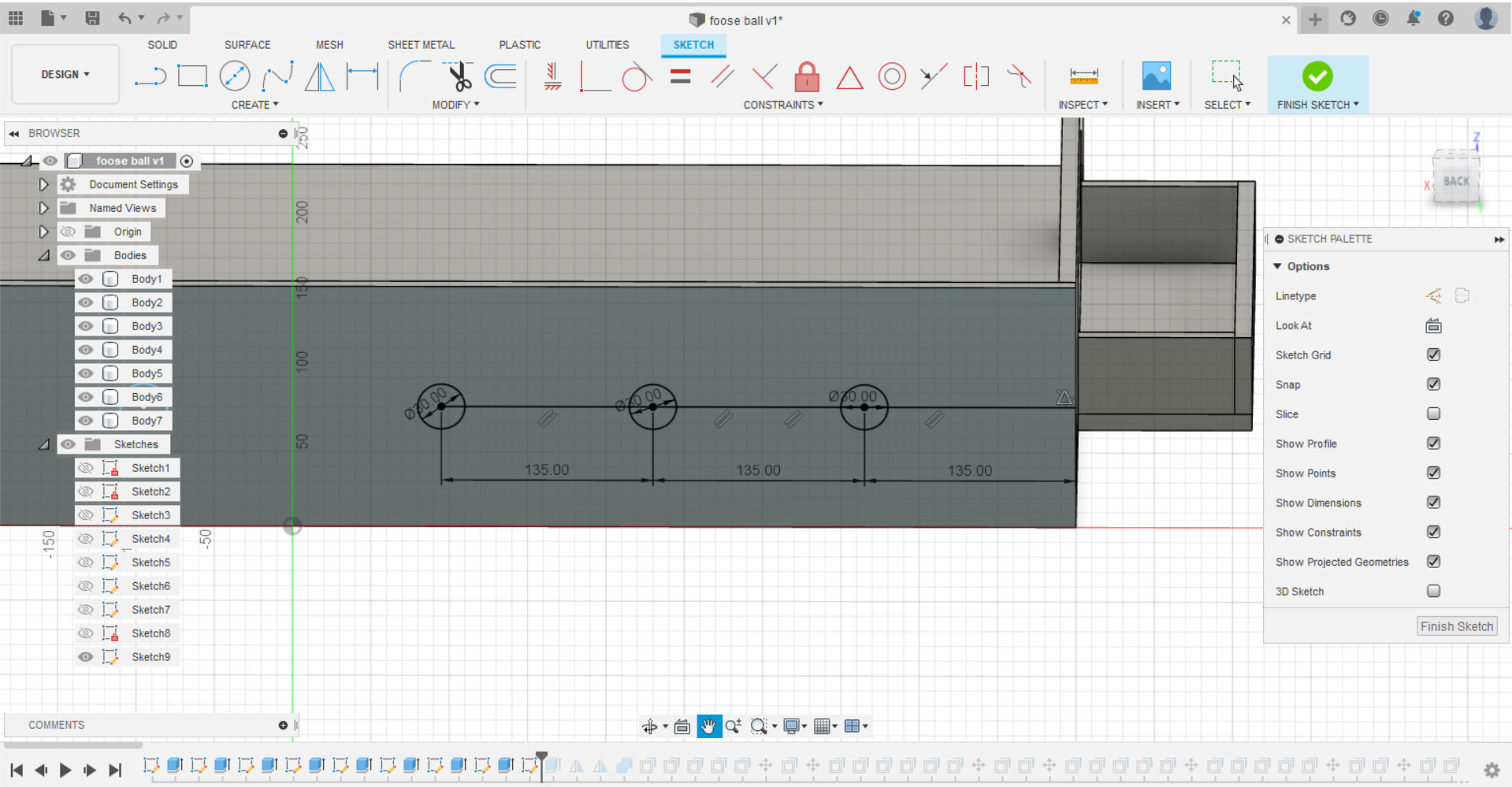
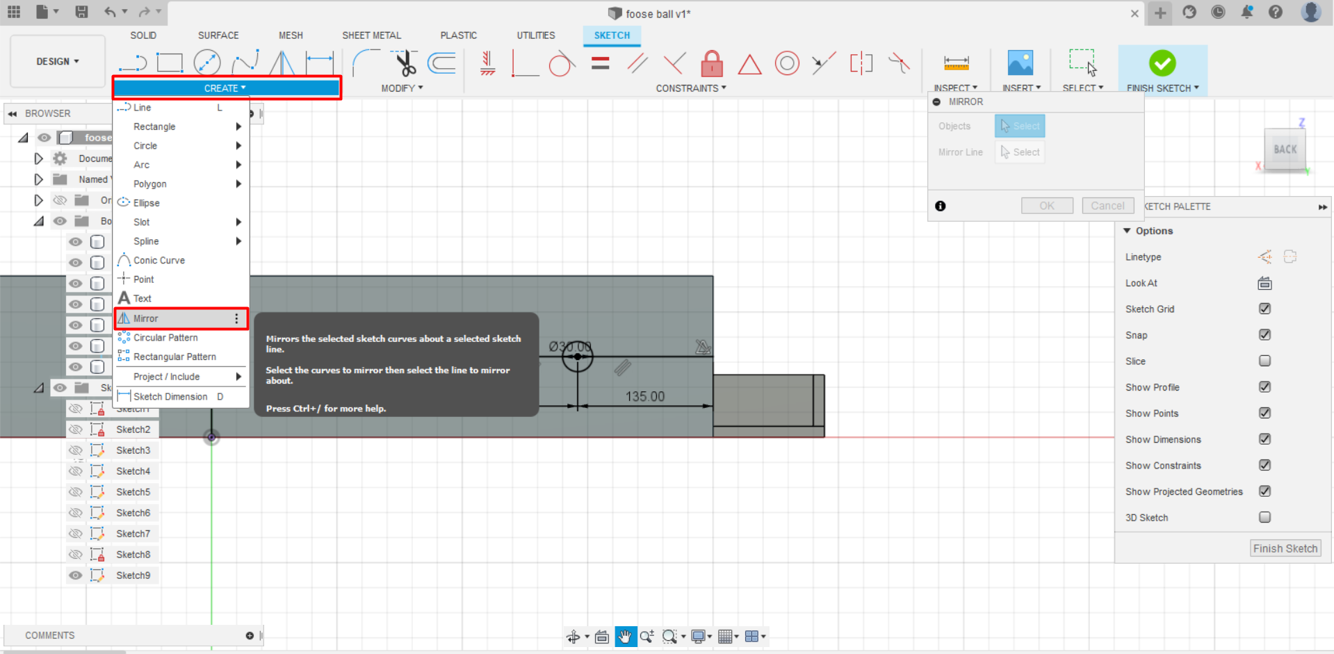
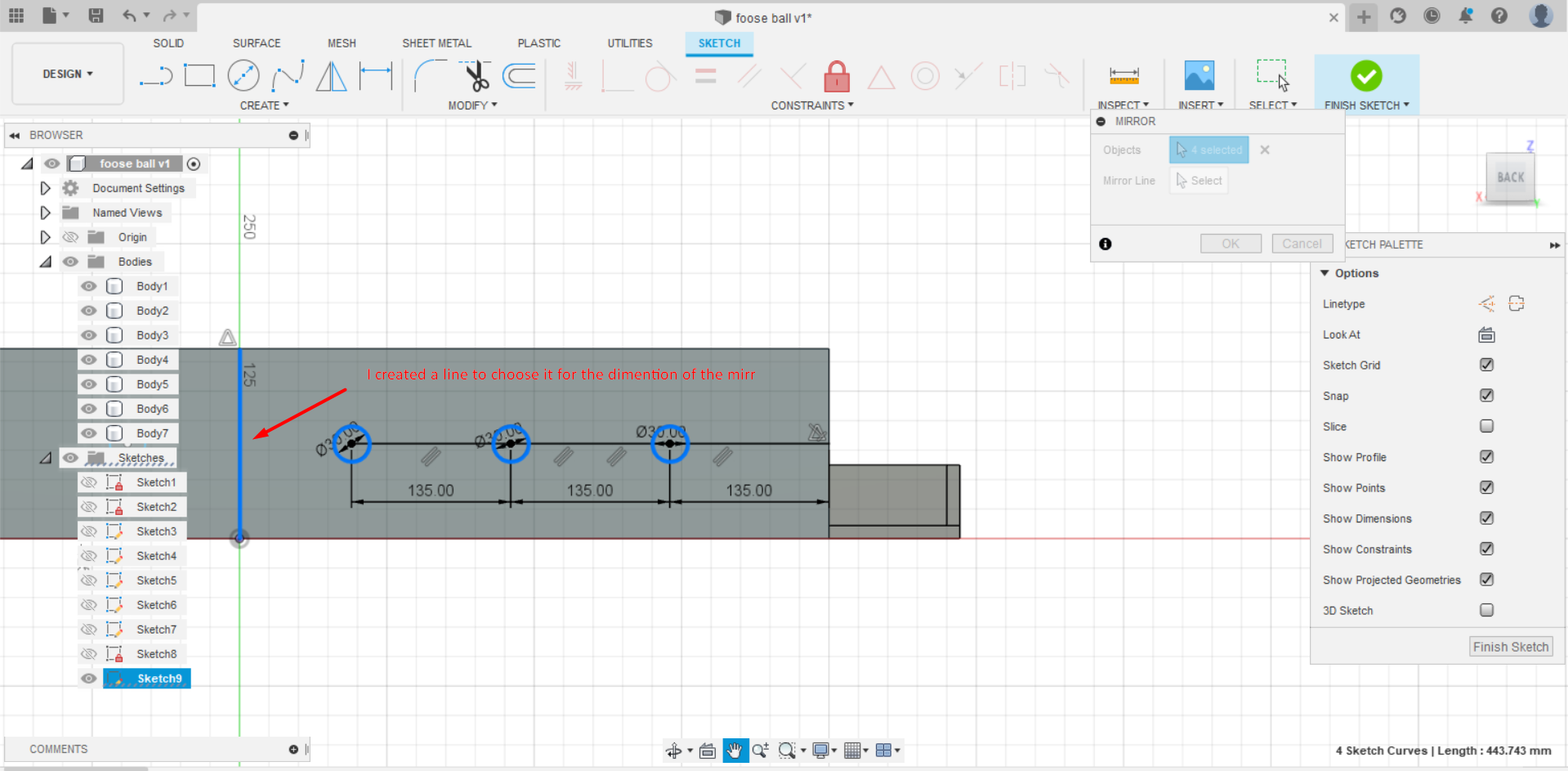
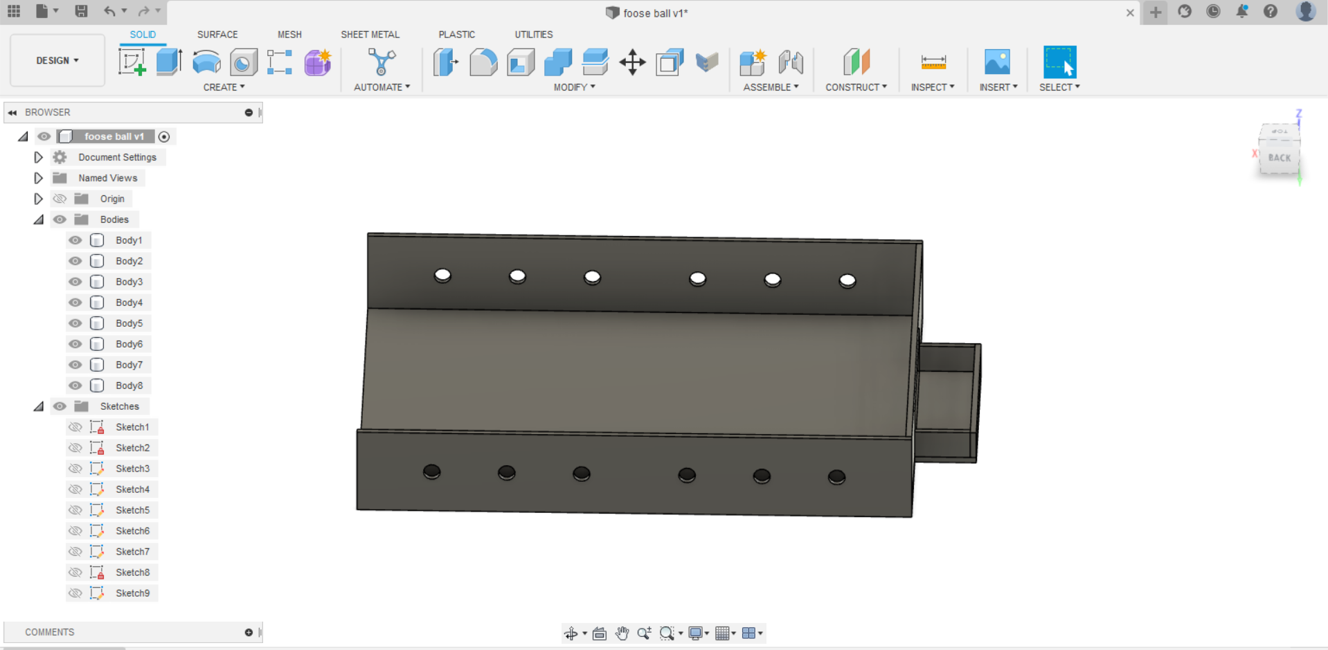
- Then, I started to make the side wall of the fooseball by adding a new sketch on the side of the goal wall. Additionally, I drew three circles on the right side with a diameter of 30 mm but i fixed them later to 27 mm after measuring the diameter size of the stick which was 22 mm and then I used the mirror to have them on the left side too. Finally, I selected all of them and unfilled them.
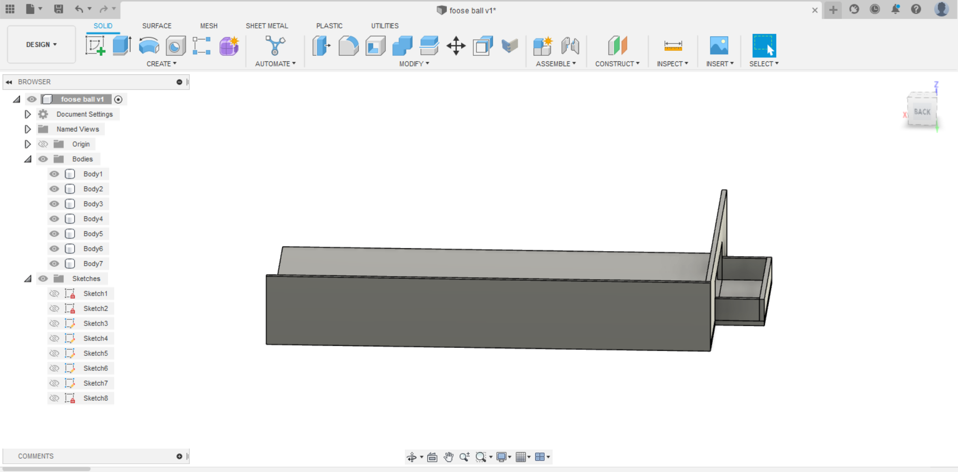
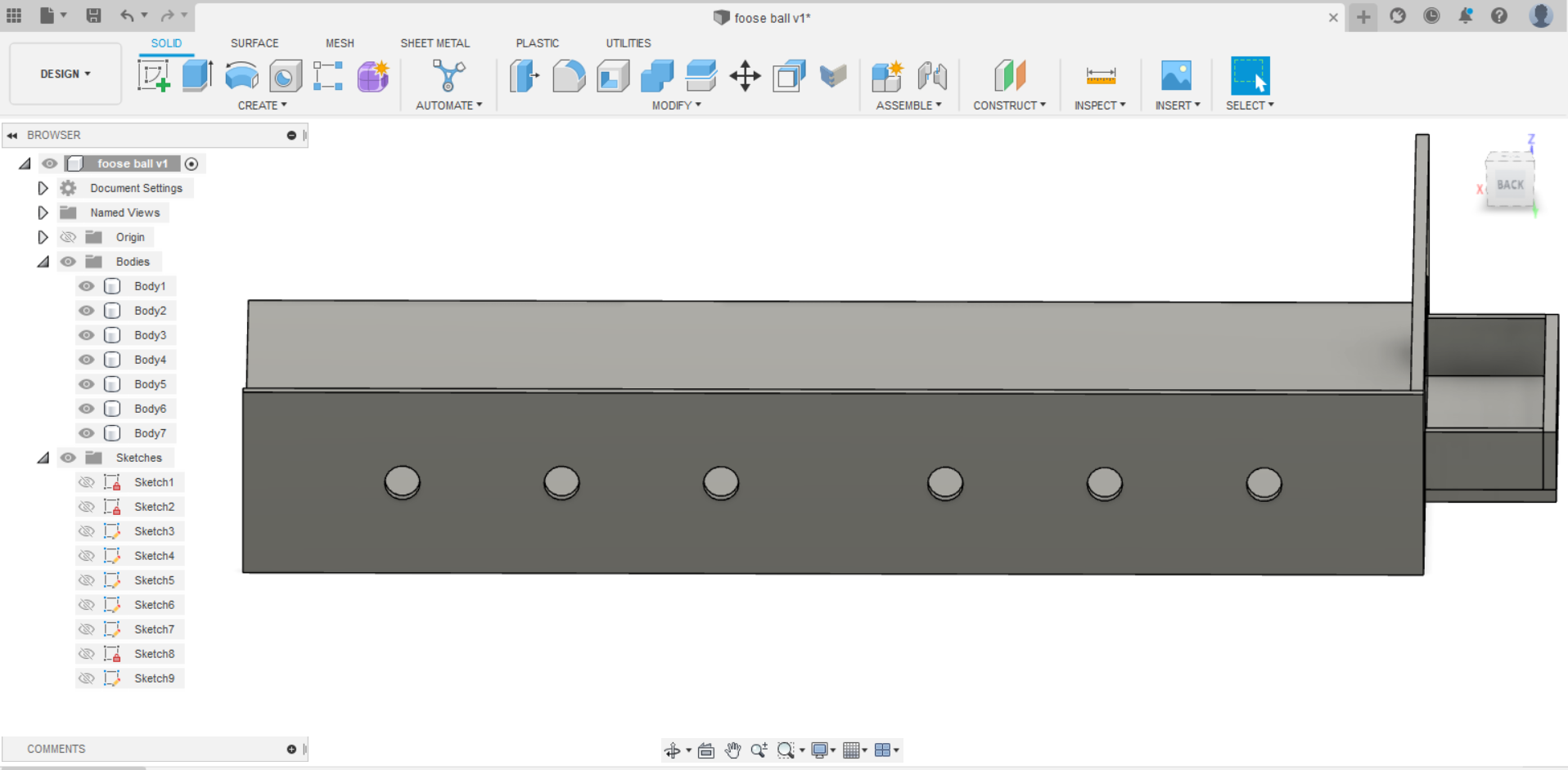
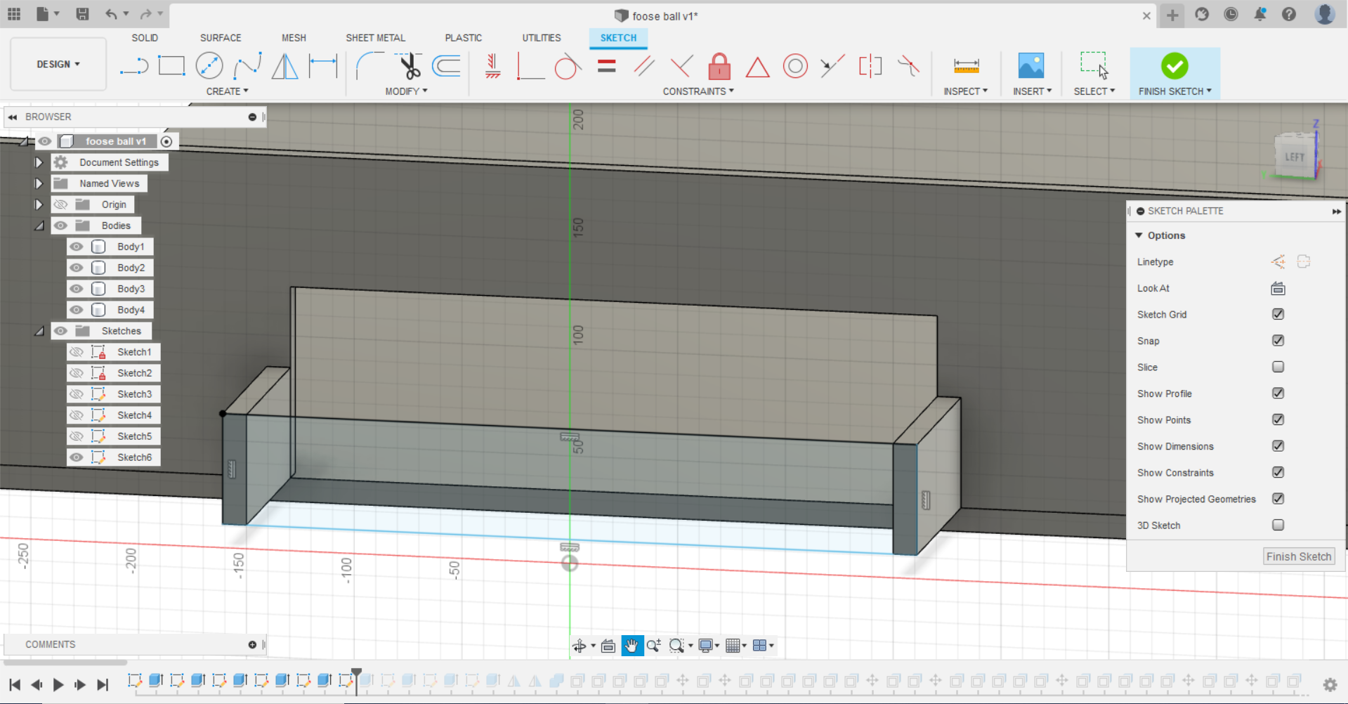
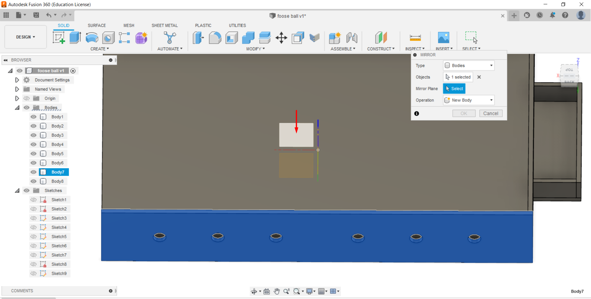
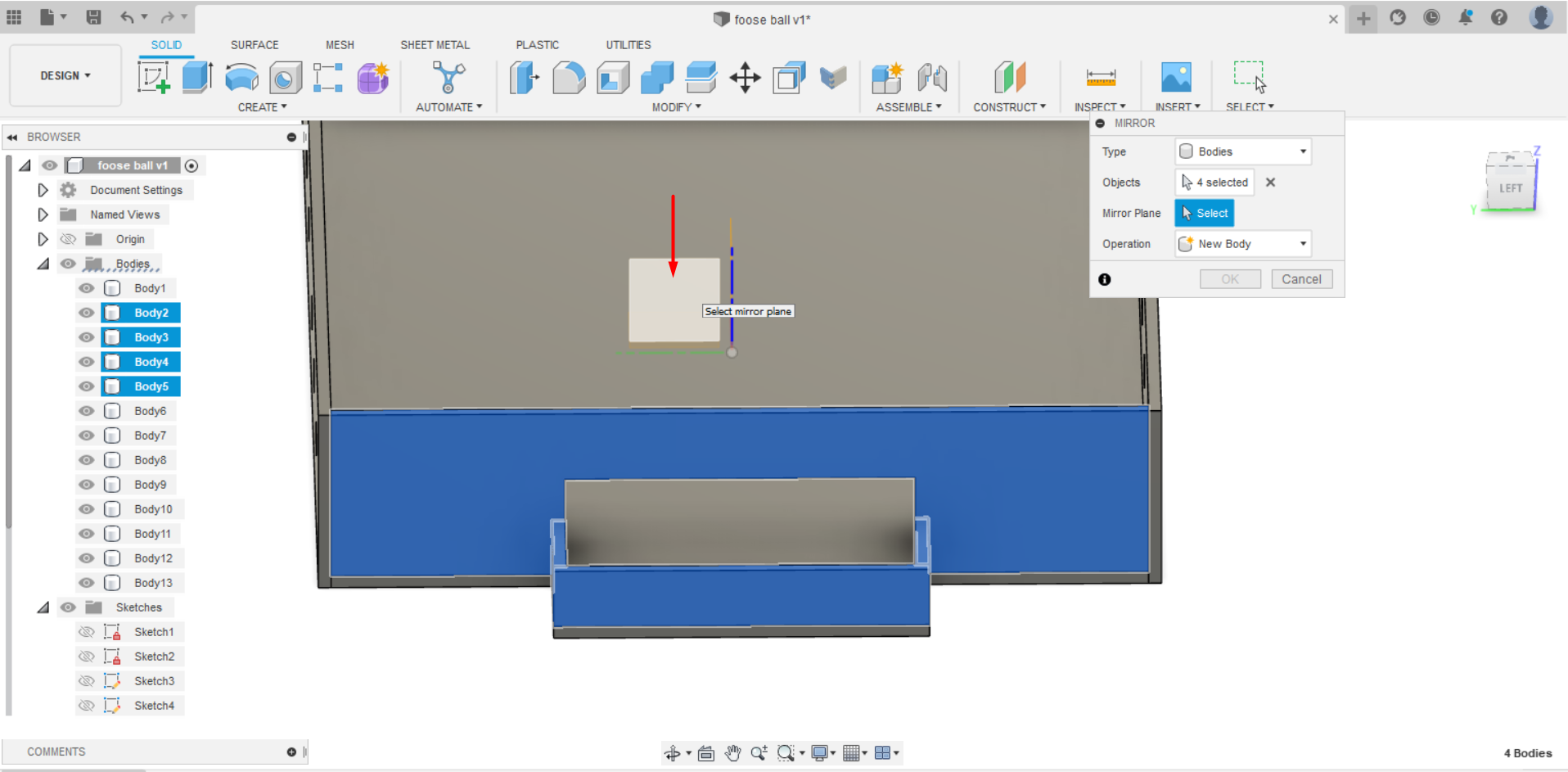
- And now I used the mirror to duplicate the side wall of the fooseball as well as the front goal.
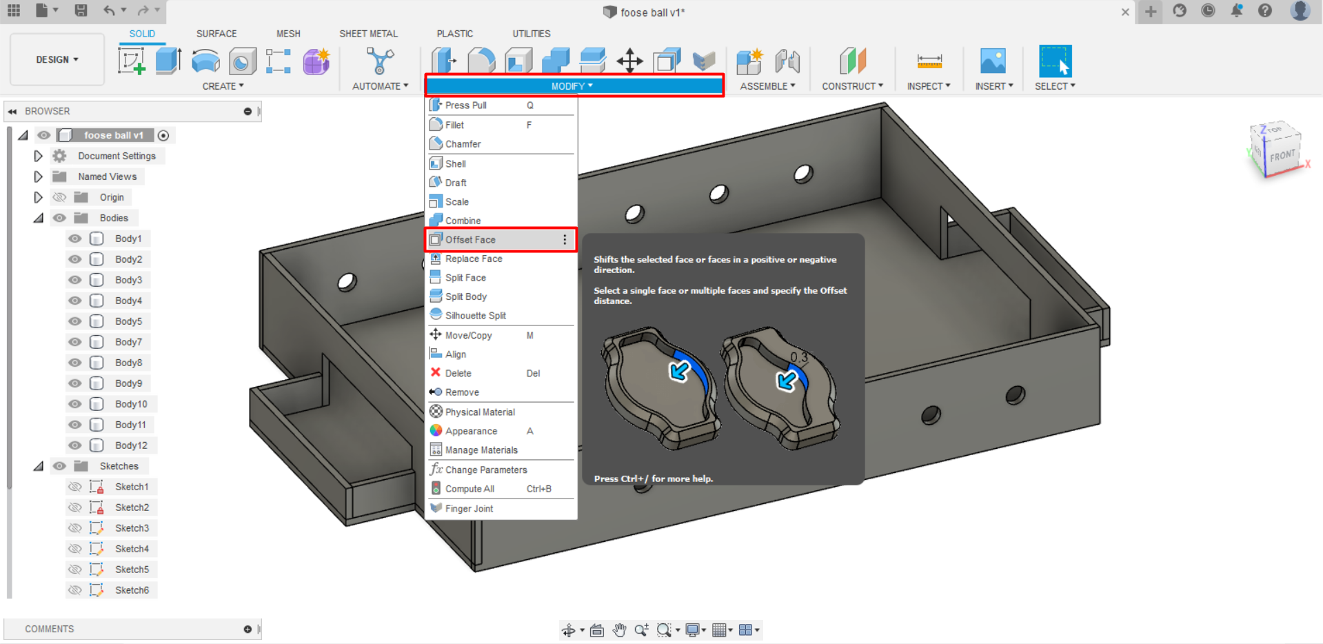
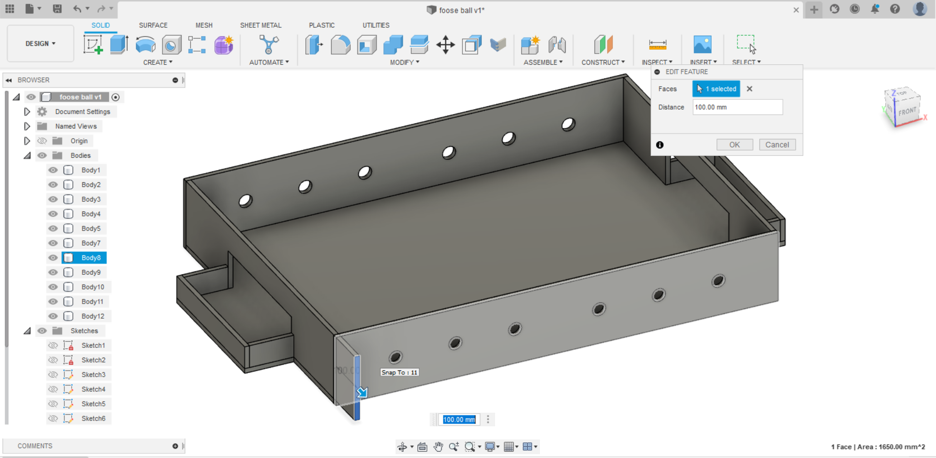
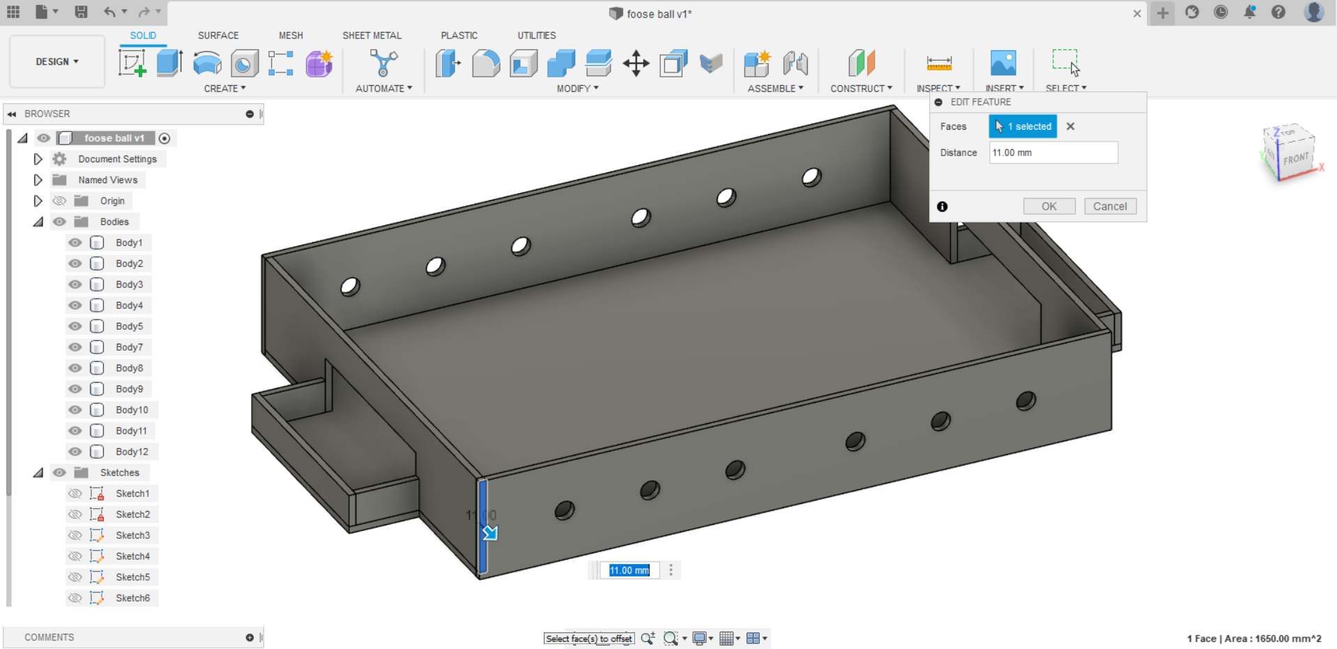
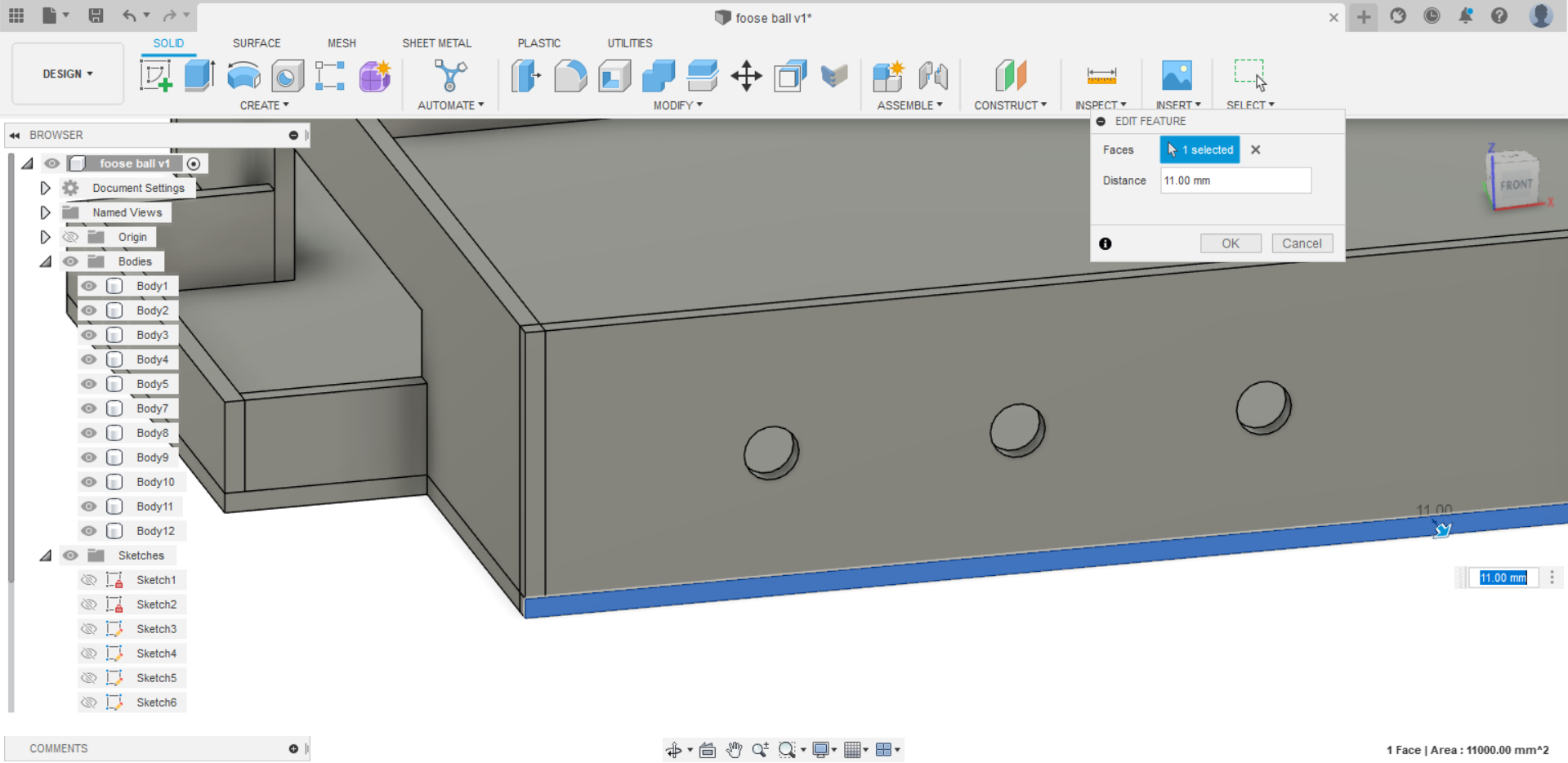
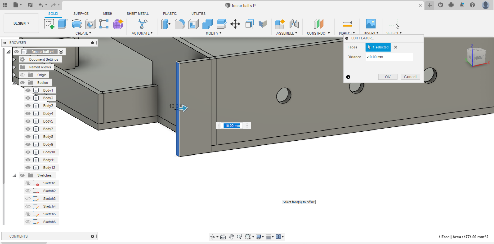
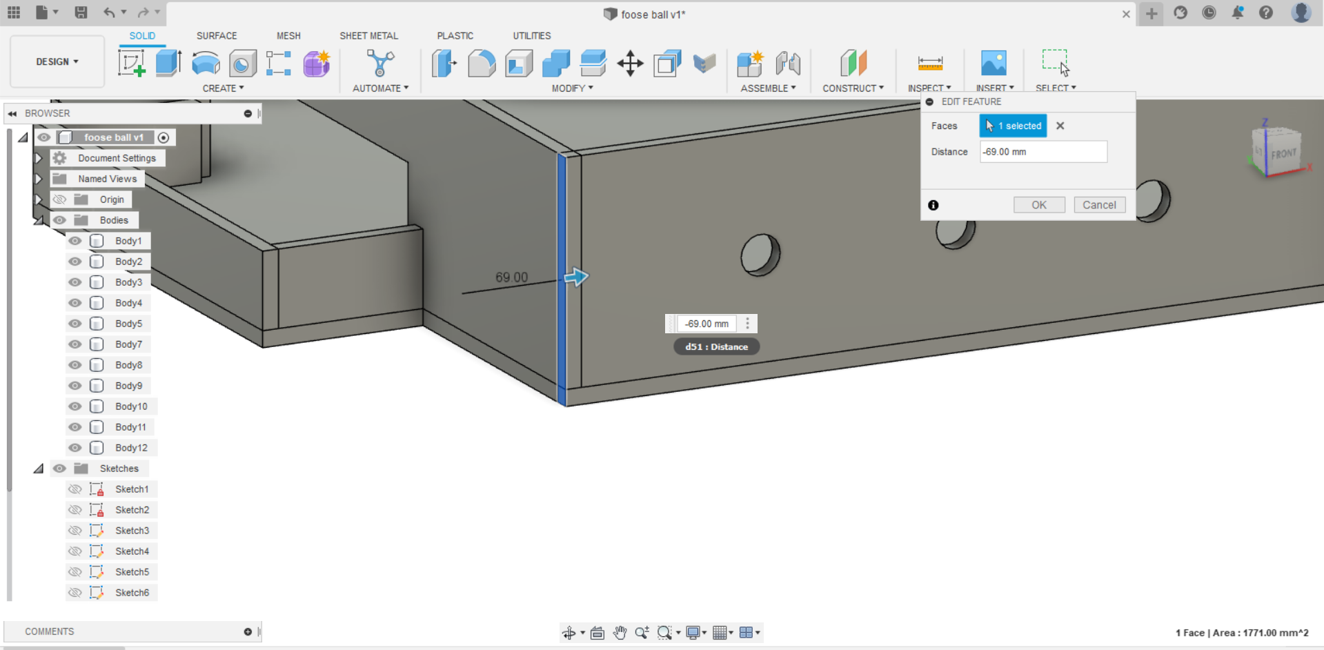
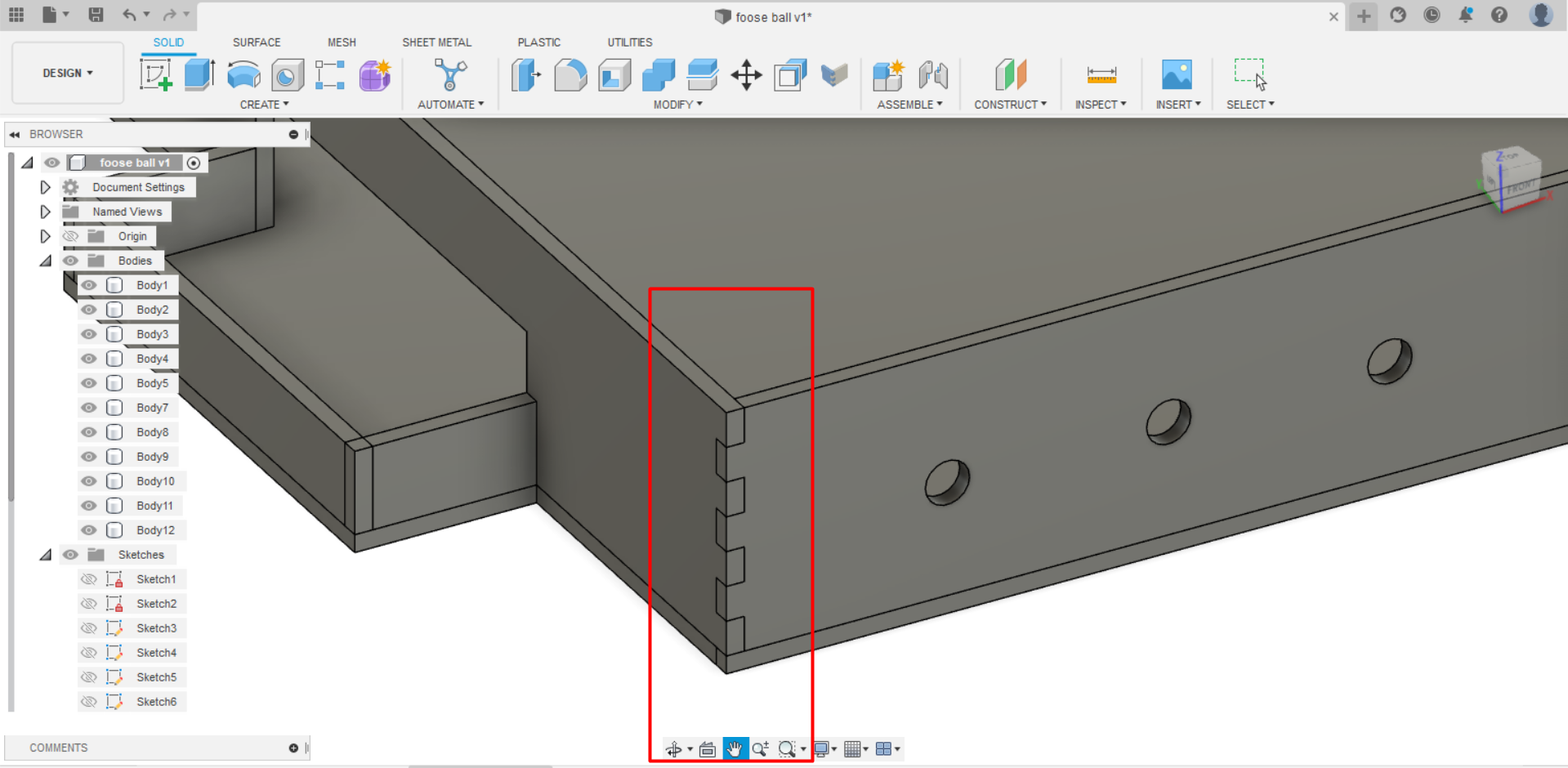
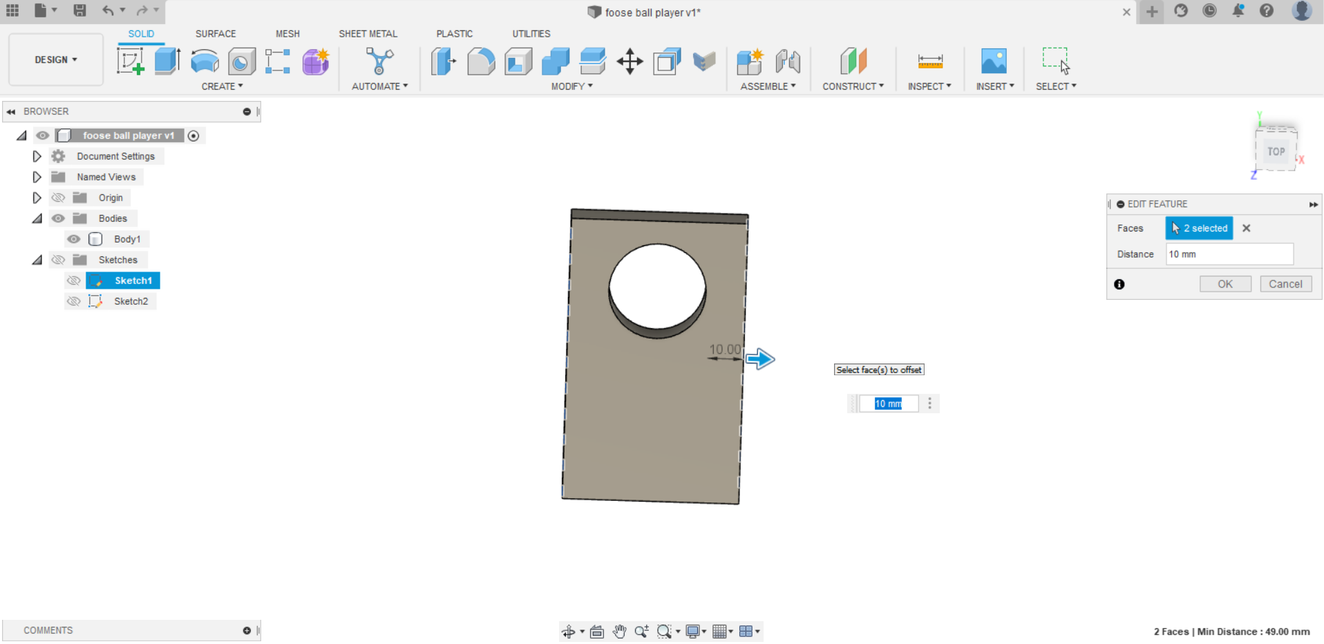
- Next, for the joints, I used finger joints in my design but before starting adding the joints, I had to edit my design with the offset face because finger joints require that each two bodies to overlap so it would be able create the joints. Moreover, i downloaded an add-in for Autodesk Fusion 360 that can help with creating finger joints. This is the link to donwload the add-in Finger joint add-in.
An example of what i mean by overlapping two bodies
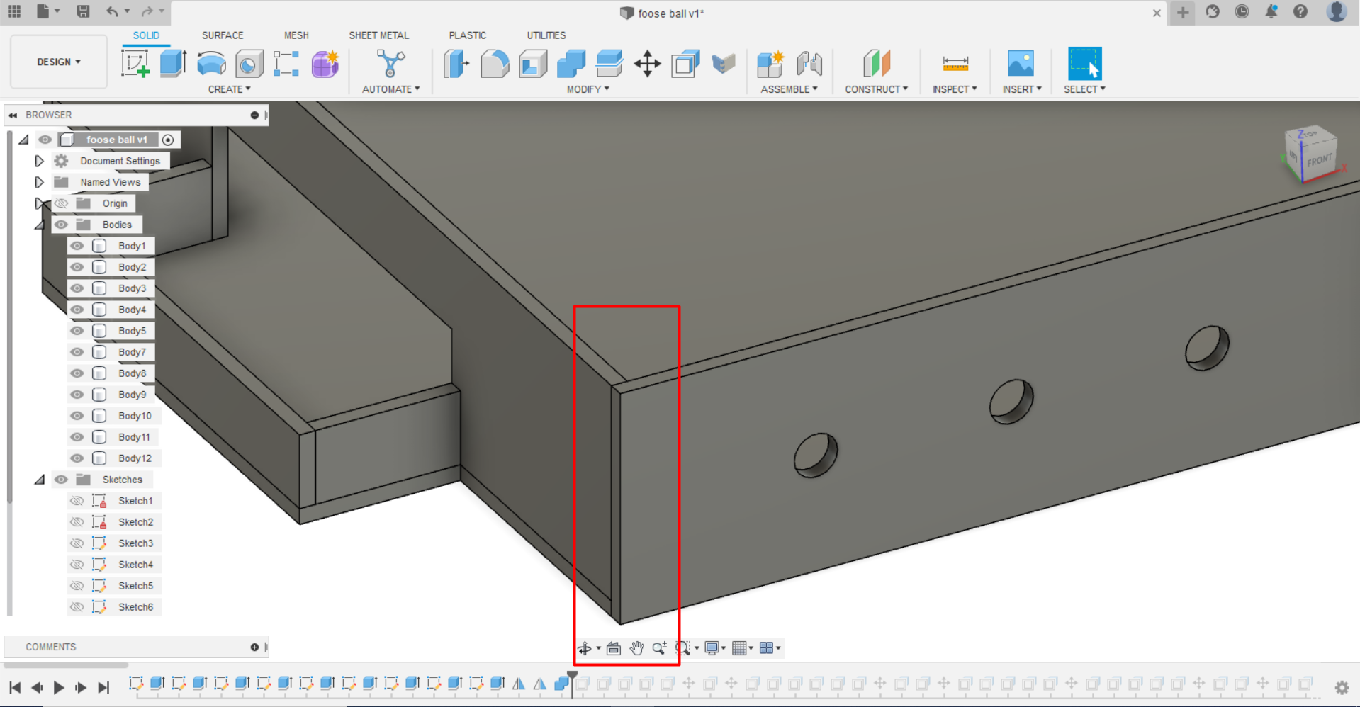
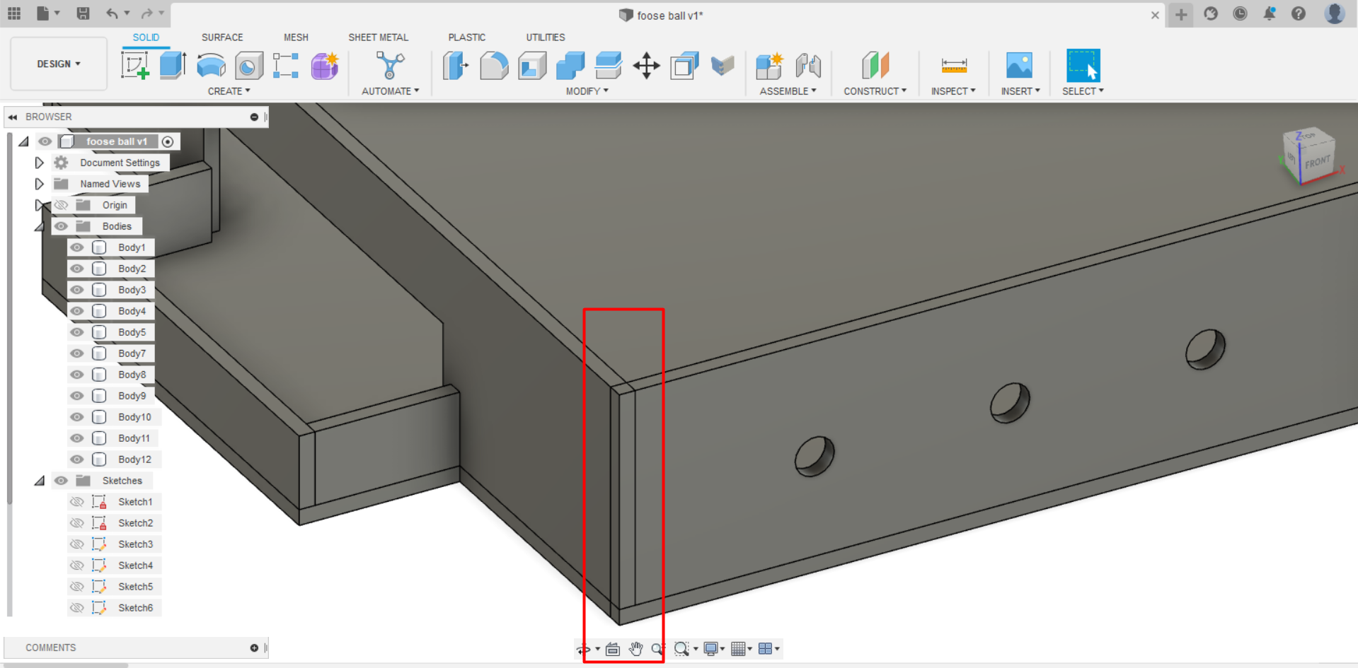
The result of the offset face and the joints in the corner
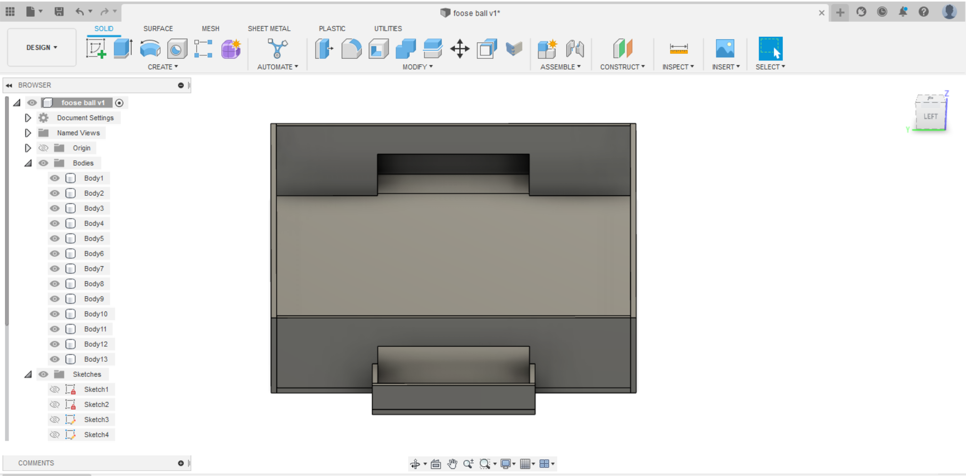
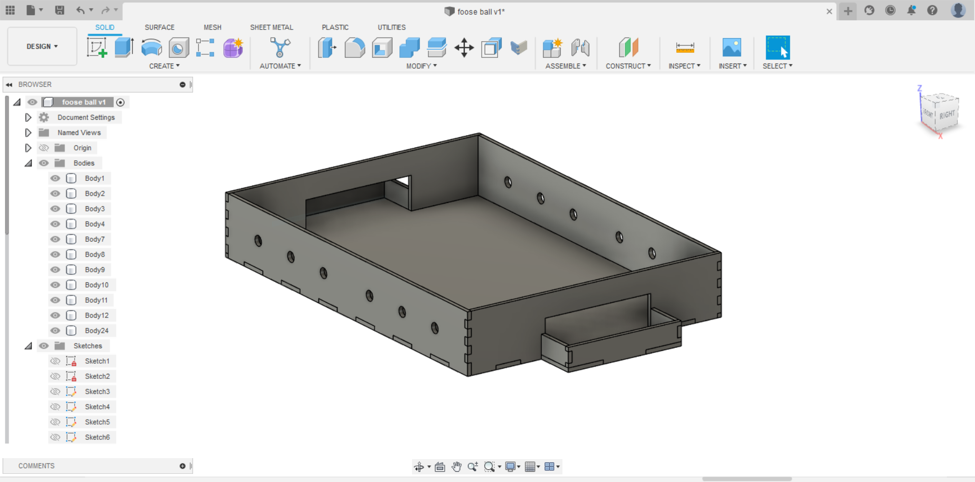
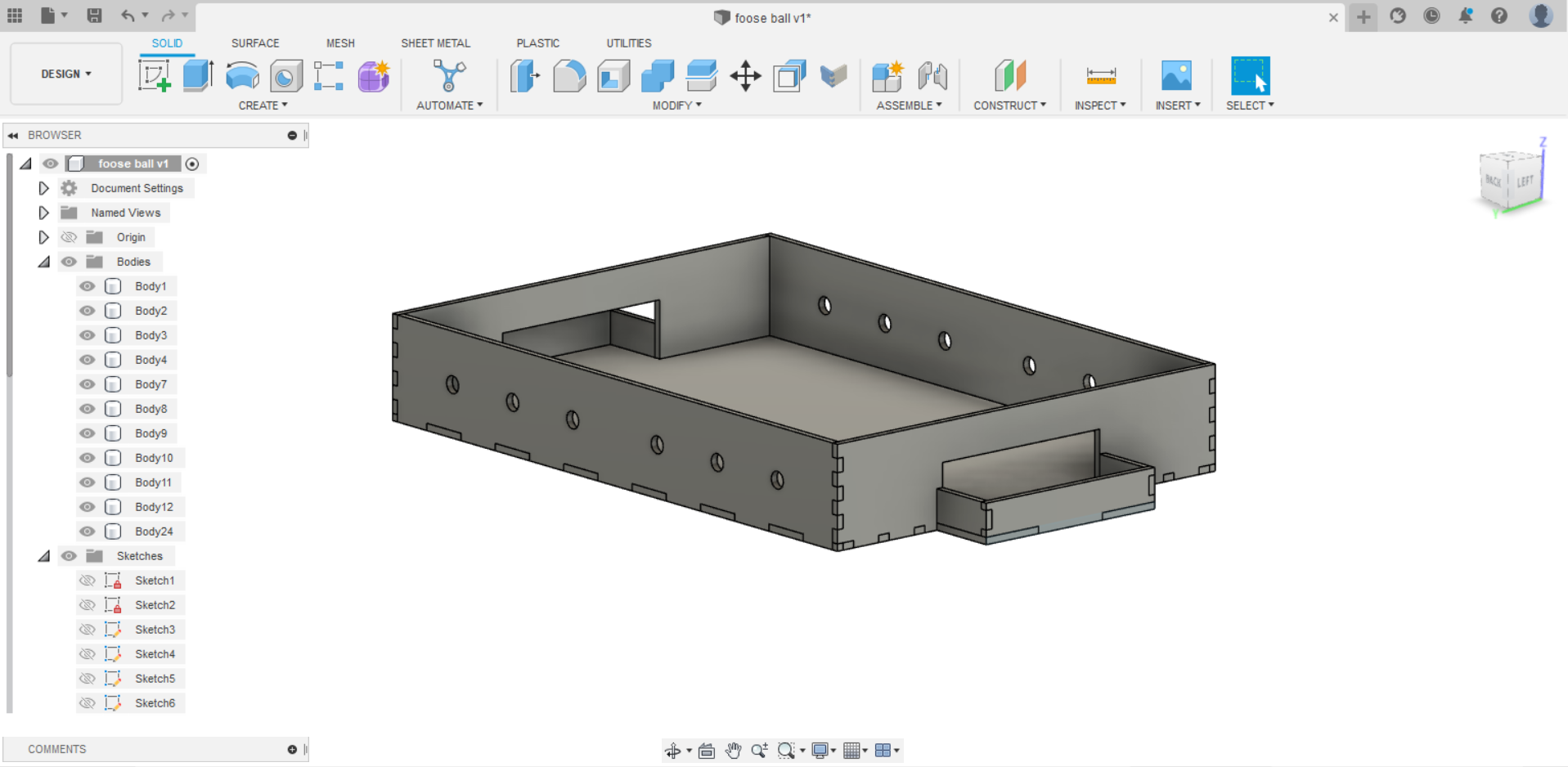
The result after being done from editing the design and adding all the joints
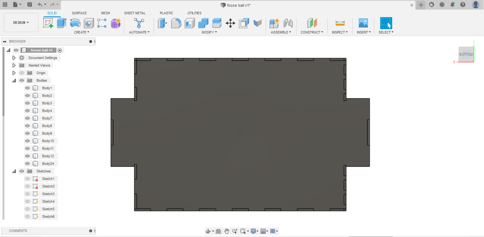
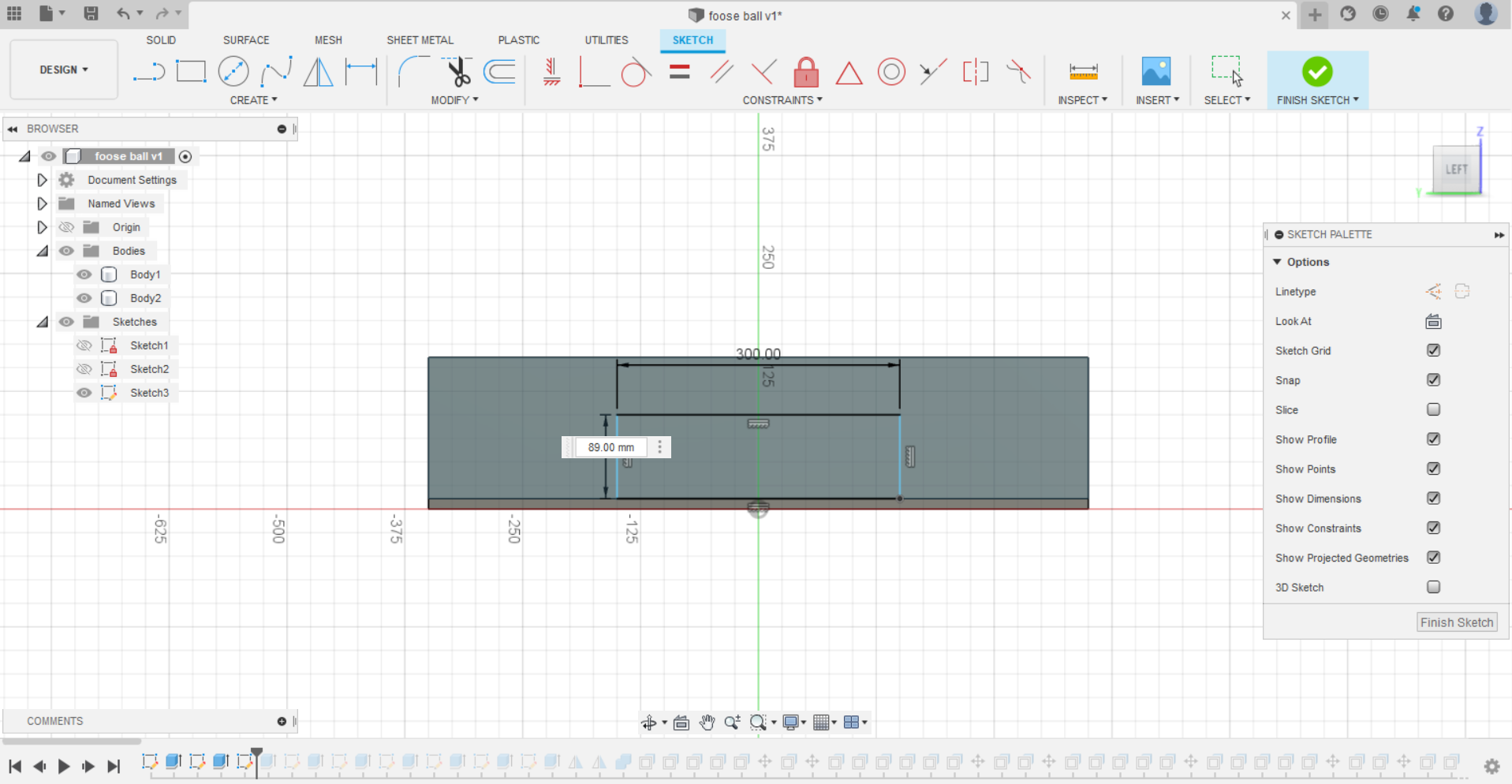
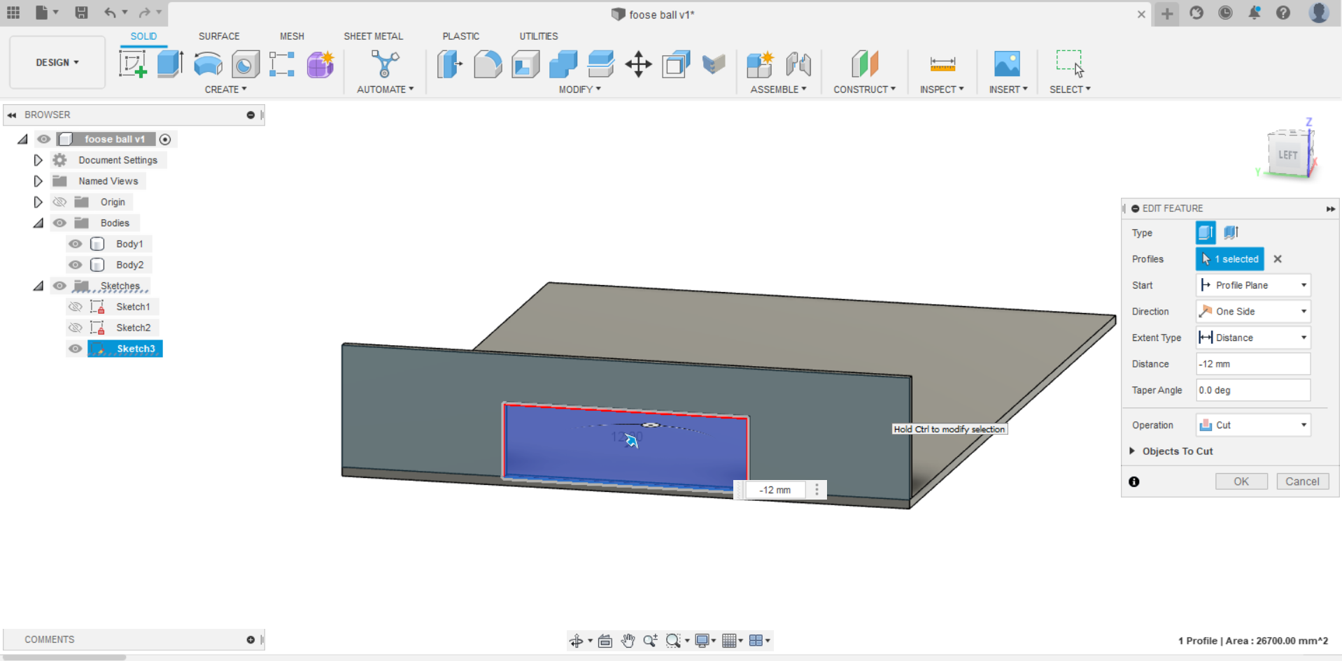
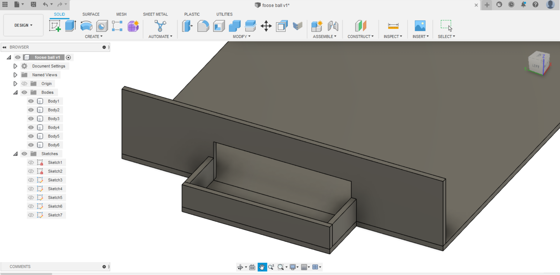
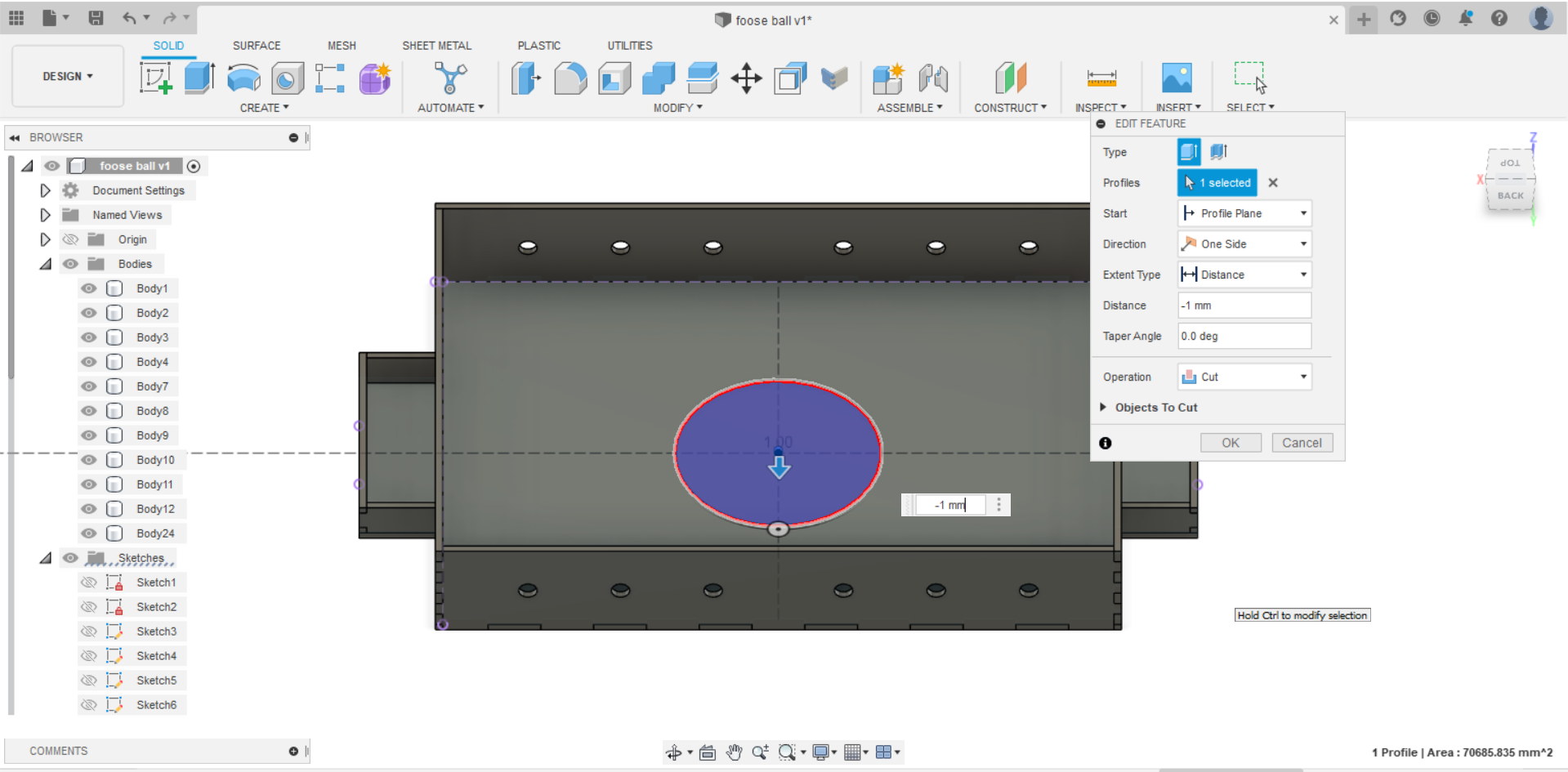
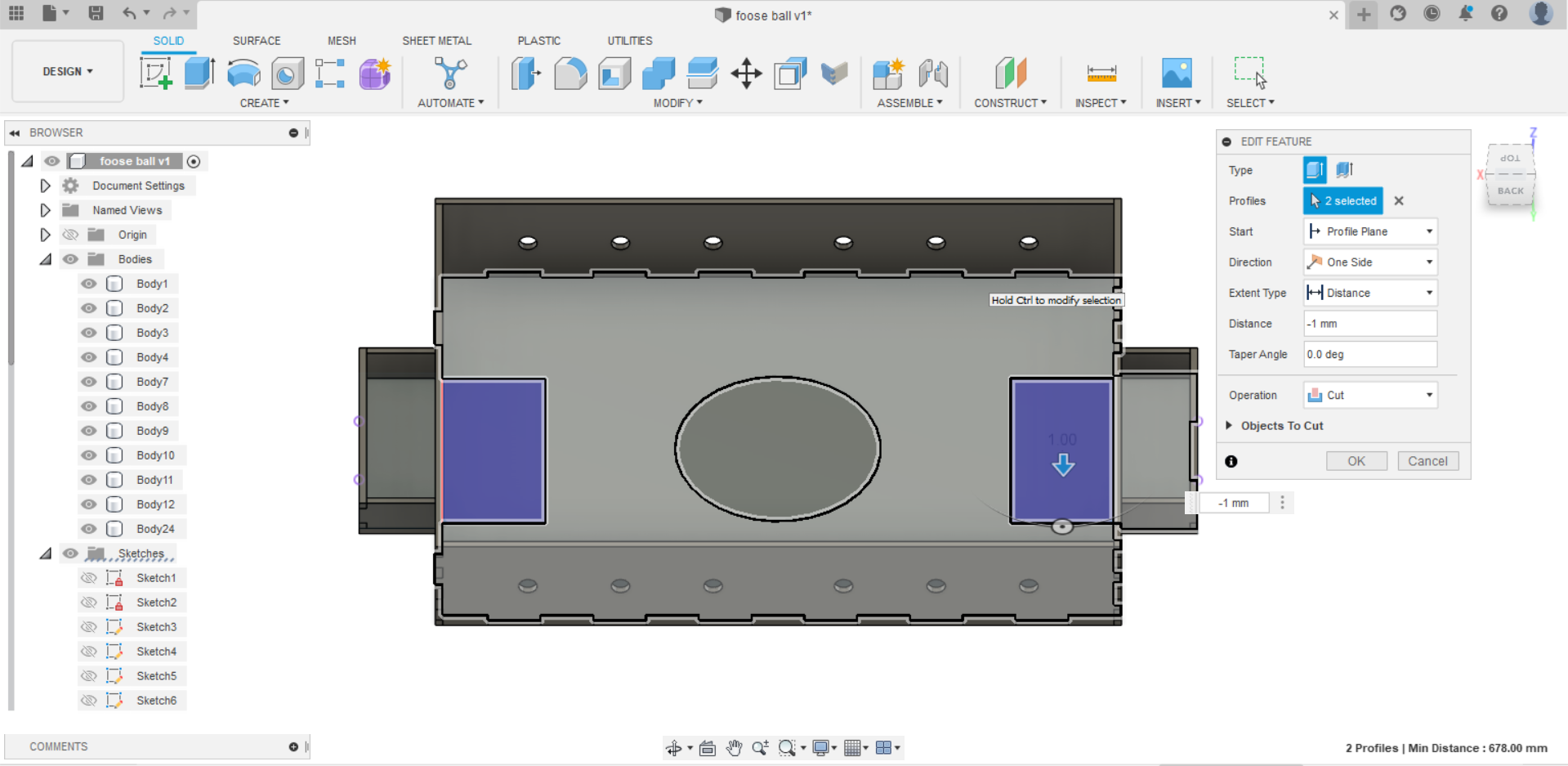
- For the finishing touches, I added two sketches to the base to design the circle in the center and the two rectangles that are each positioned close to its goal.
Hint: The circle and the rectangles are extruded with -1 mm because i want the machine to not go deep while cutting them.
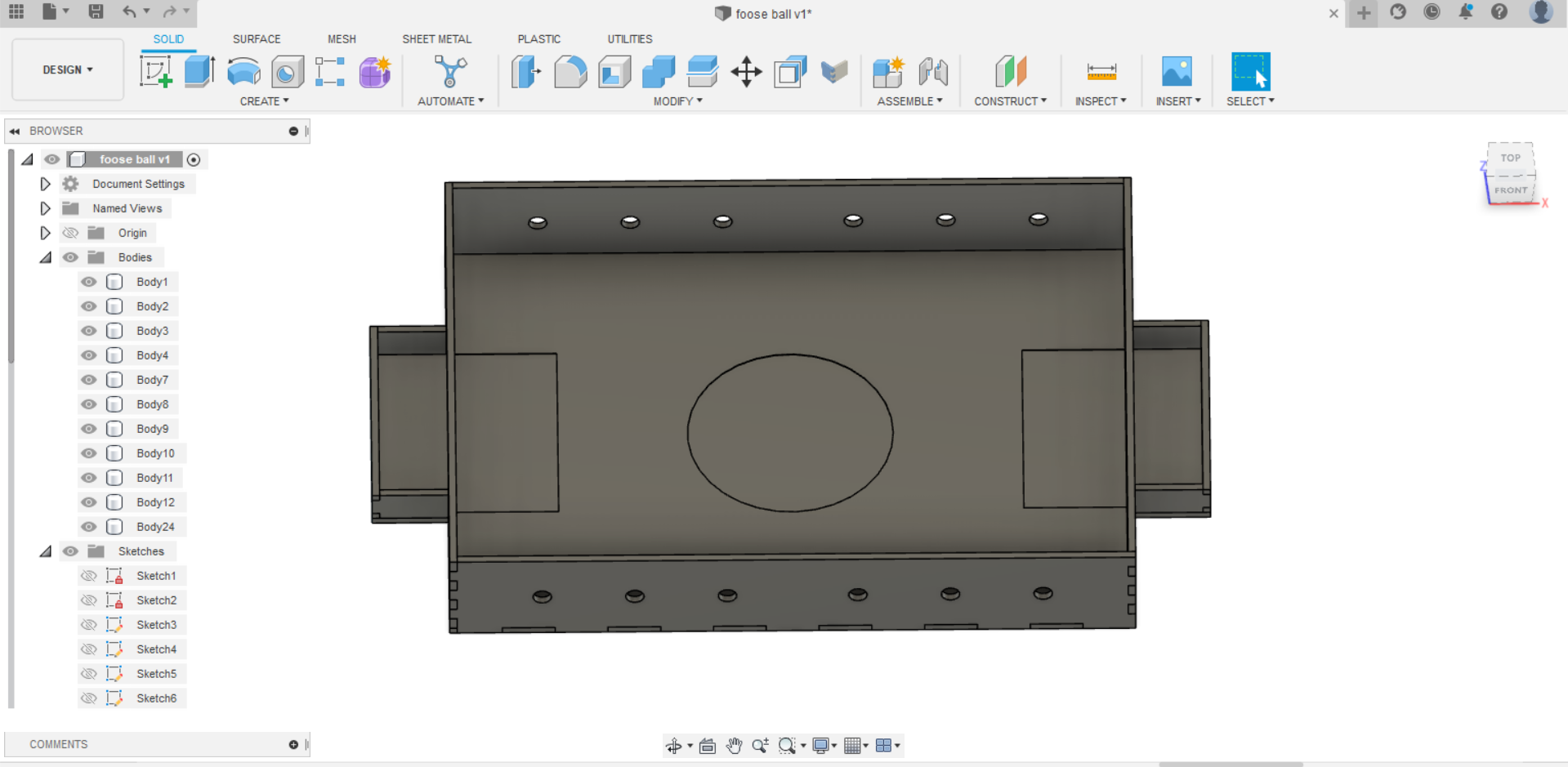
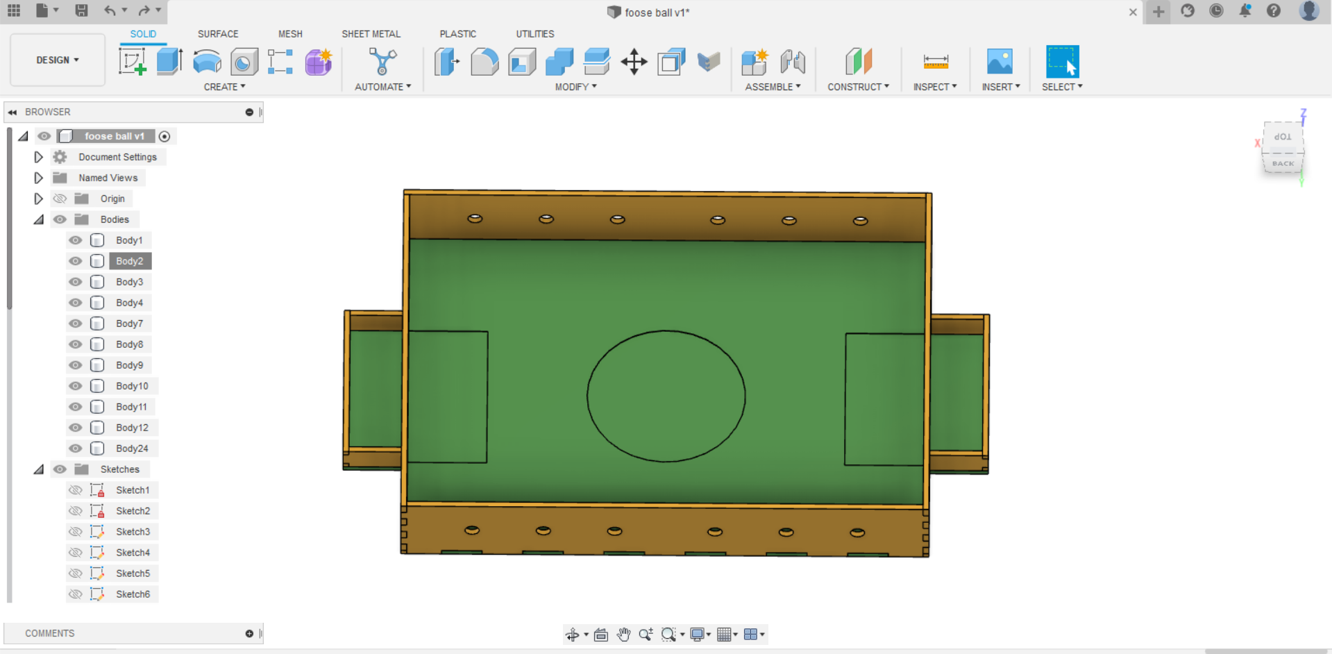
The final result
And preview the model below in 3D
To download the original file - Download
Designing the players
After I was done from the fooseball, I started to design the players for it. I created the design for one player and decided to let the CNC machine cut 24 players.
Hint: They are 12 players, but because the material is so weak, I chose to pair up every two. Additionally, before I started creating the player, I measured the length I would need it to be using a measuring tape and discovered that it was 80 mm.
- First, I started with creating a rectangle with the size of 29 mm depth and 80 mm width.
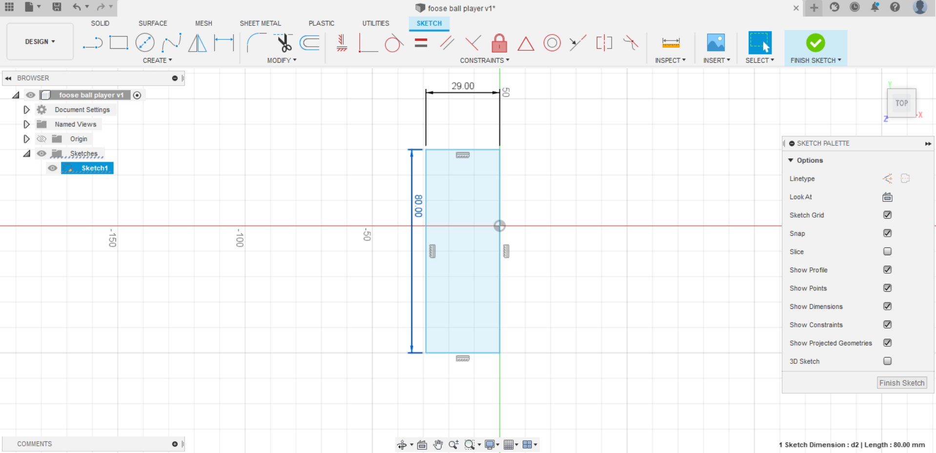
- Then I extruded it with a thickness of 11 mm.
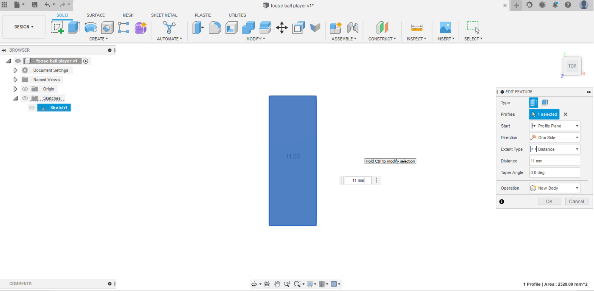
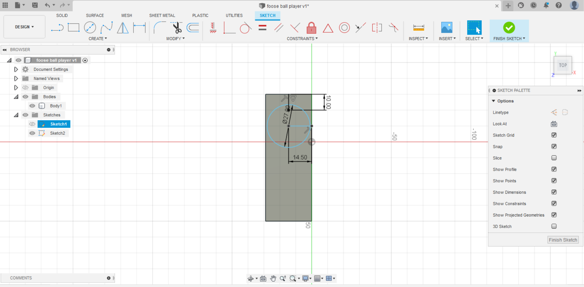
- Next, I added a sketch on the rectangle to draw the circle with a diameter of 27 mm and unfill it
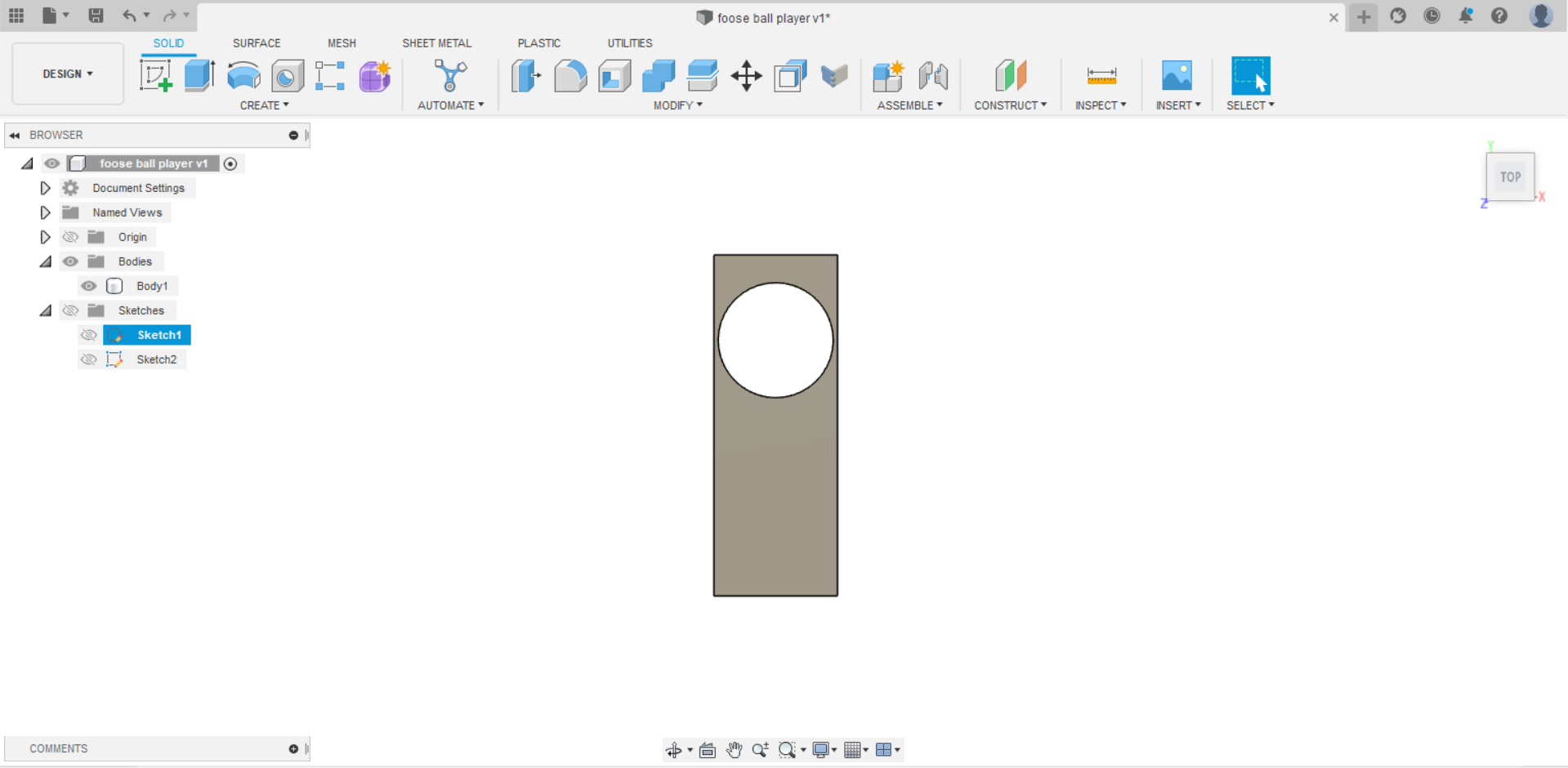
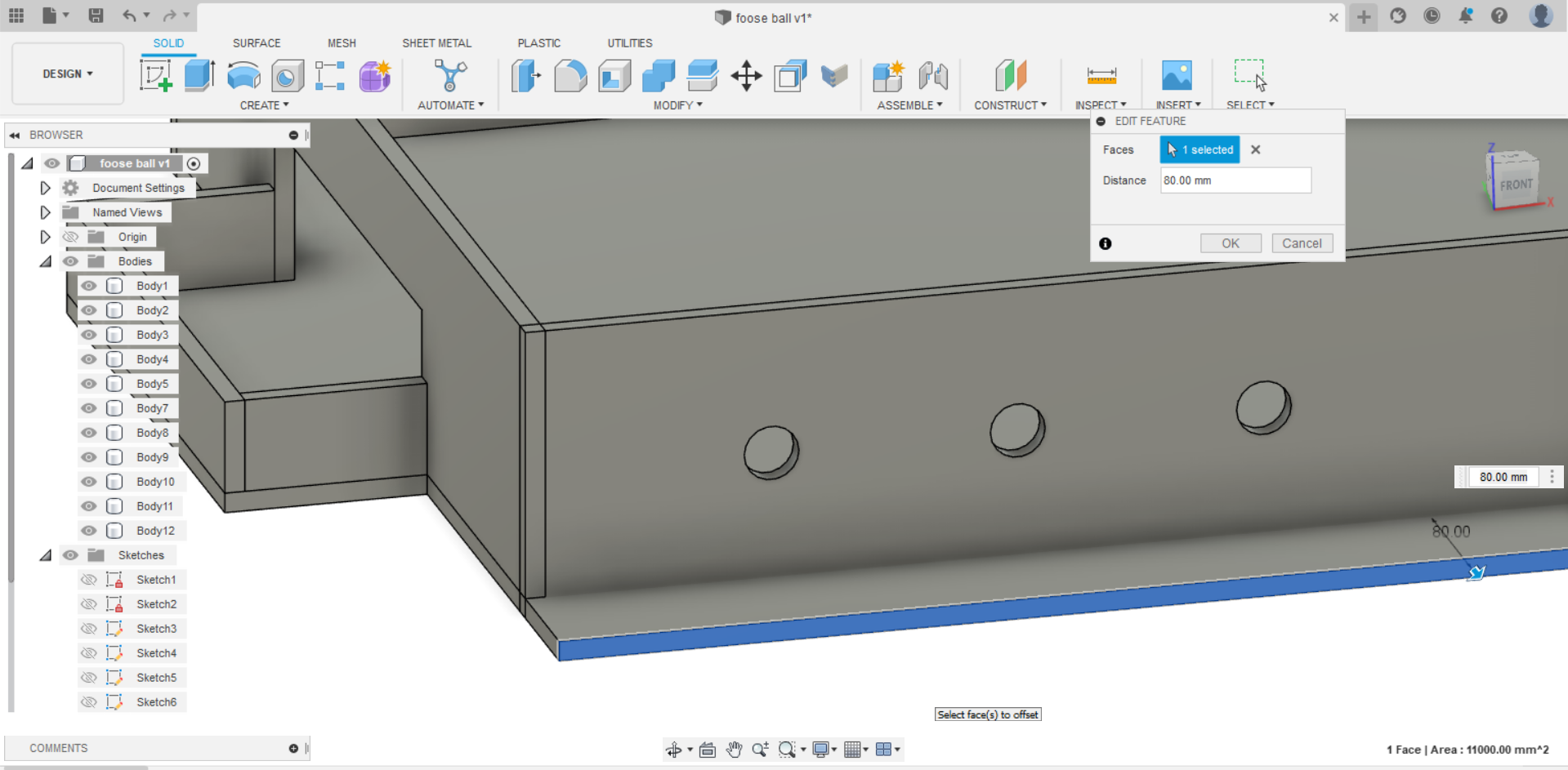
- As we can see, the depth needs to be raised because the design could shatter if the circle’s sides are too thin. As a result, I edited it using the offset face and added some rounded edges.
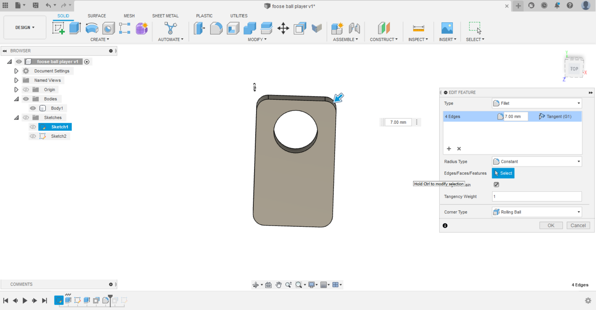
- The final result
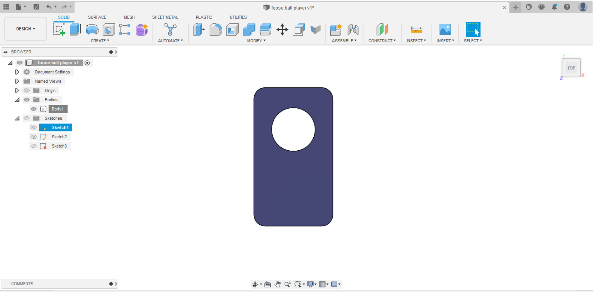
And preview the model below in 3D
To download the original file - Download
The cutting process using CNC machine
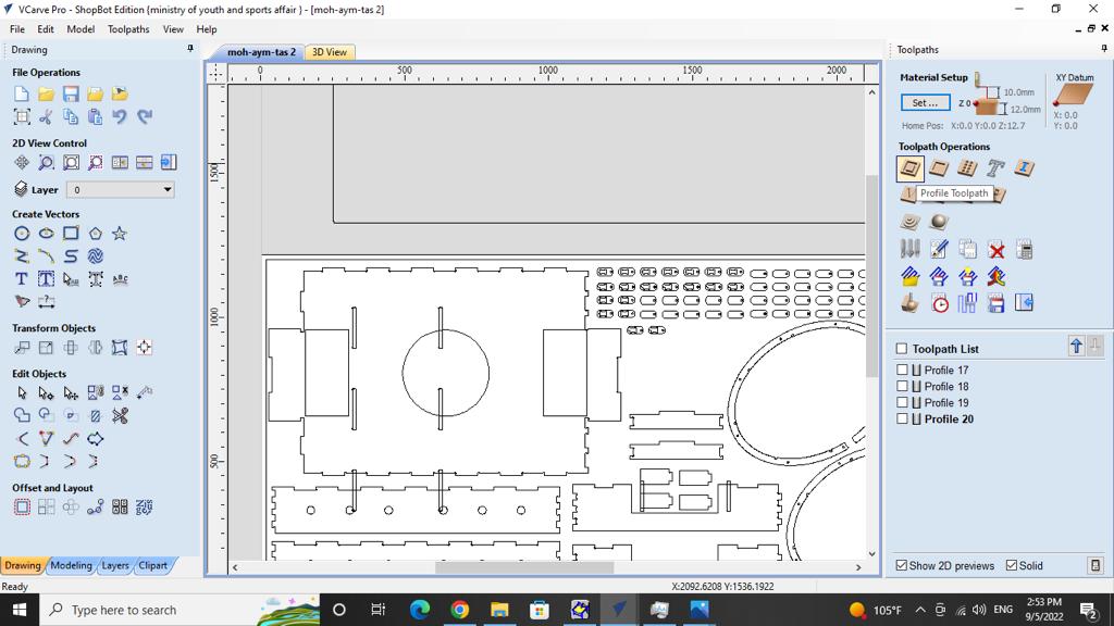
Vcarve Pro: VCarve Pro provides a powerful but intuitive software solution for creating and cutting parts on a CNC Router. VCarve Pro gives you the power to produce complex 2D patterns with profile, pocket, drill and inlay toolpaths, plus gives you the ability to create designs with v-carving textures as well as import and machine unlimited Vectric 3D clipart or single model files.
The Toolpath:
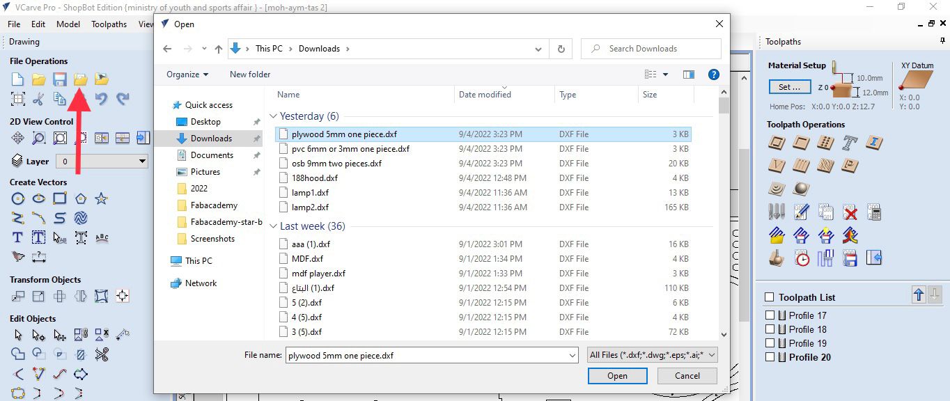
- First, save the design file as dxf and open it in VCarve Pro in order to construct the toolpath.
To download the DXF files
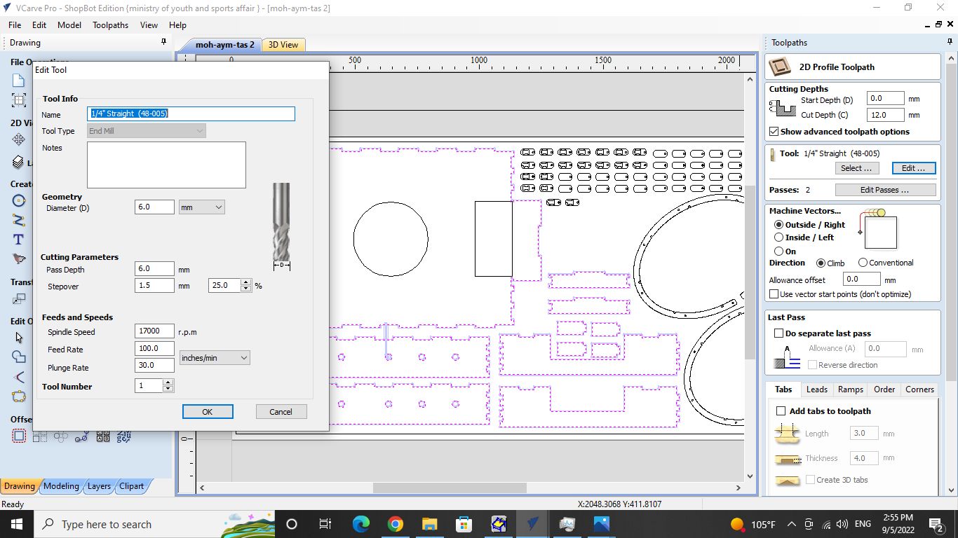
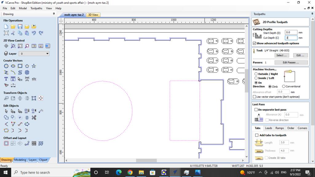
- The spindle speed for the drill was determined to be 17000 revolutions per minute. Additionally, the drill’s working speed which is the feed rate, was adjusted to 100 and the cut depth was set to 12 mm because the thickness of the MDF material is 11 mm. In regards to the circle and rectangular shapes as well. In order to draw them rather than cut deeply, the cut depth was adjusted to 3 mm.
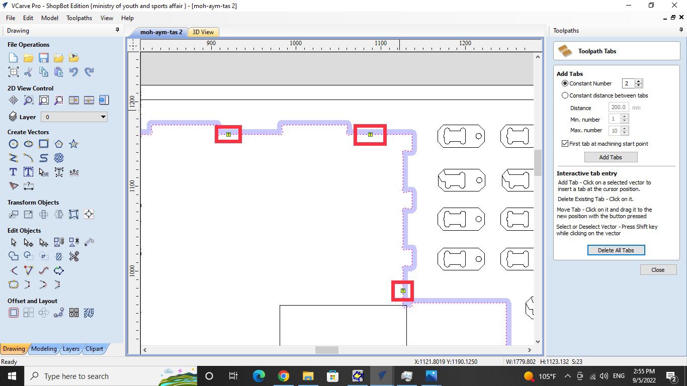
- Add some tabs on the design to let the material be fixed during the cutting process to get the highest level of accuracy.
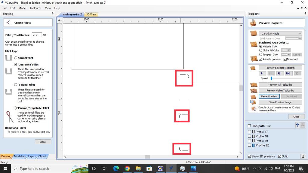
- A “Dog-Bone” fillet should be placed between each joint because when cutting materials with the CNC, a known problem is that while the CNC can make a perfect outer corner, the inner corners can never be more sharp than the diameter of the cutting tool.
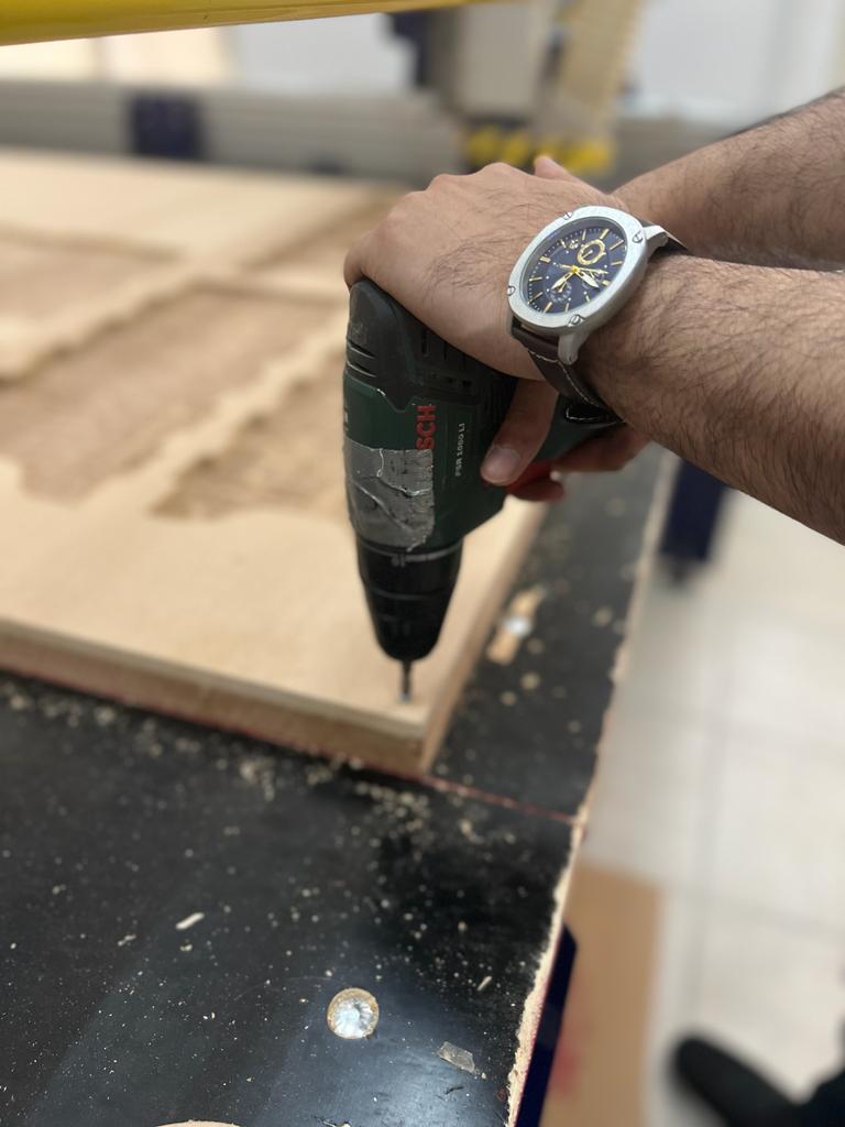
- Next, After being done from from the toolpath, I started to change the material with a new one because there was no space to cut my design on it after my colleague were done from cutting.
Hint: I need to use the screw to fix the material from the corners.

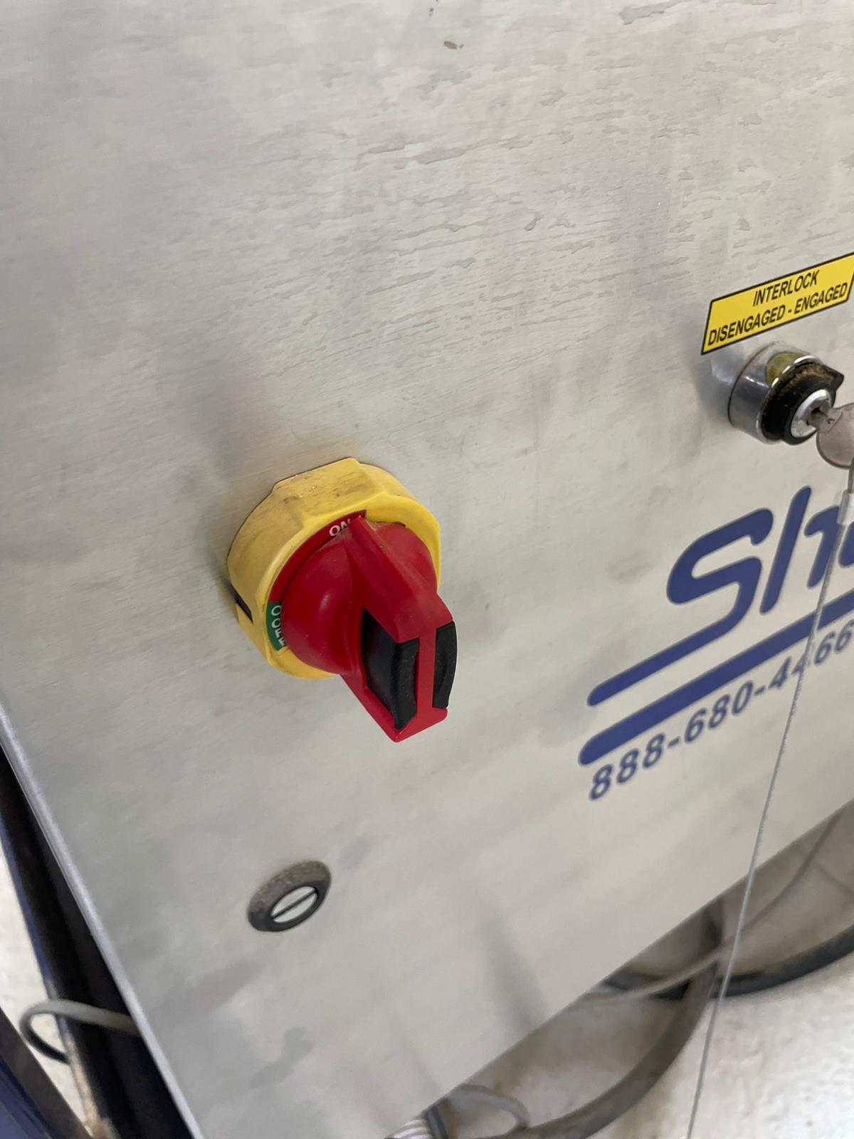
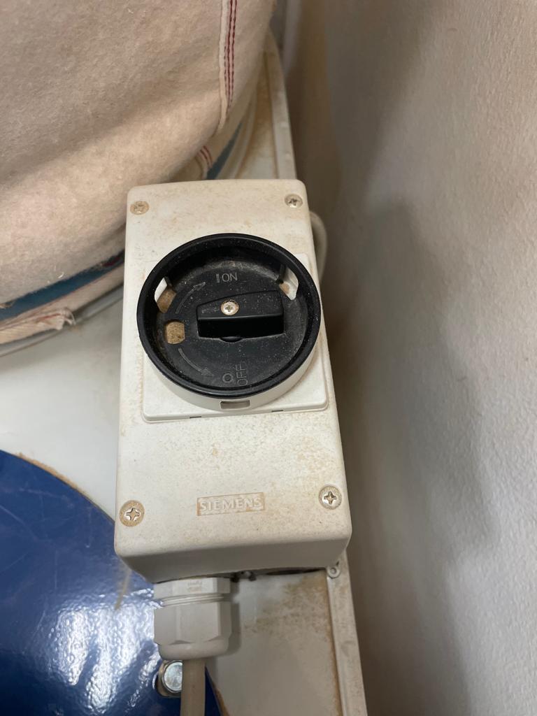
- Then, I turned on the CNC machine using the red switch on the bottom right.
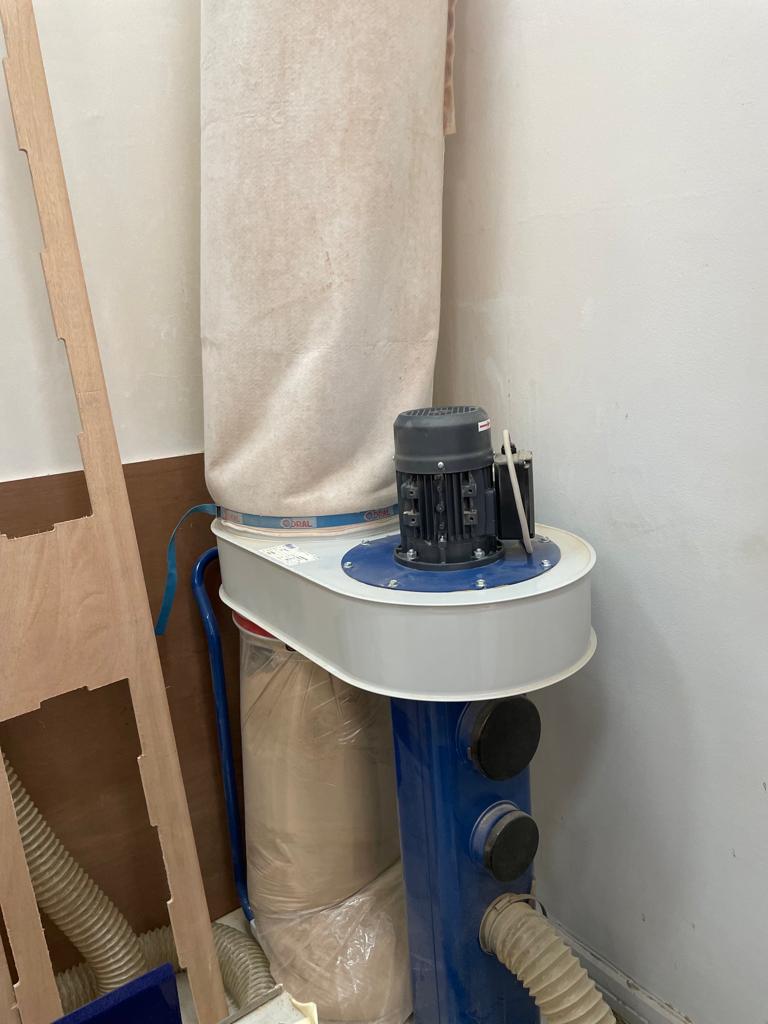
- Regarding the safety and before start cutting, Check to see if the vacuum cleaner is operational. As well as wearing safety eyewear.
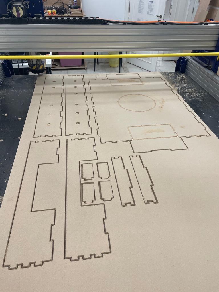
- Everything is prepared at this point, so I started to let the CNC machine cut my design as shown in the video, and the cutting process took around 15 minutes to finish.
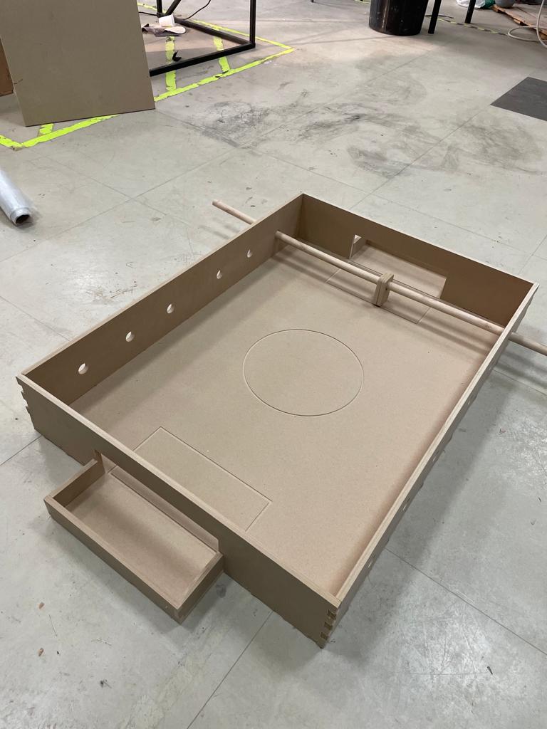
The assembling process
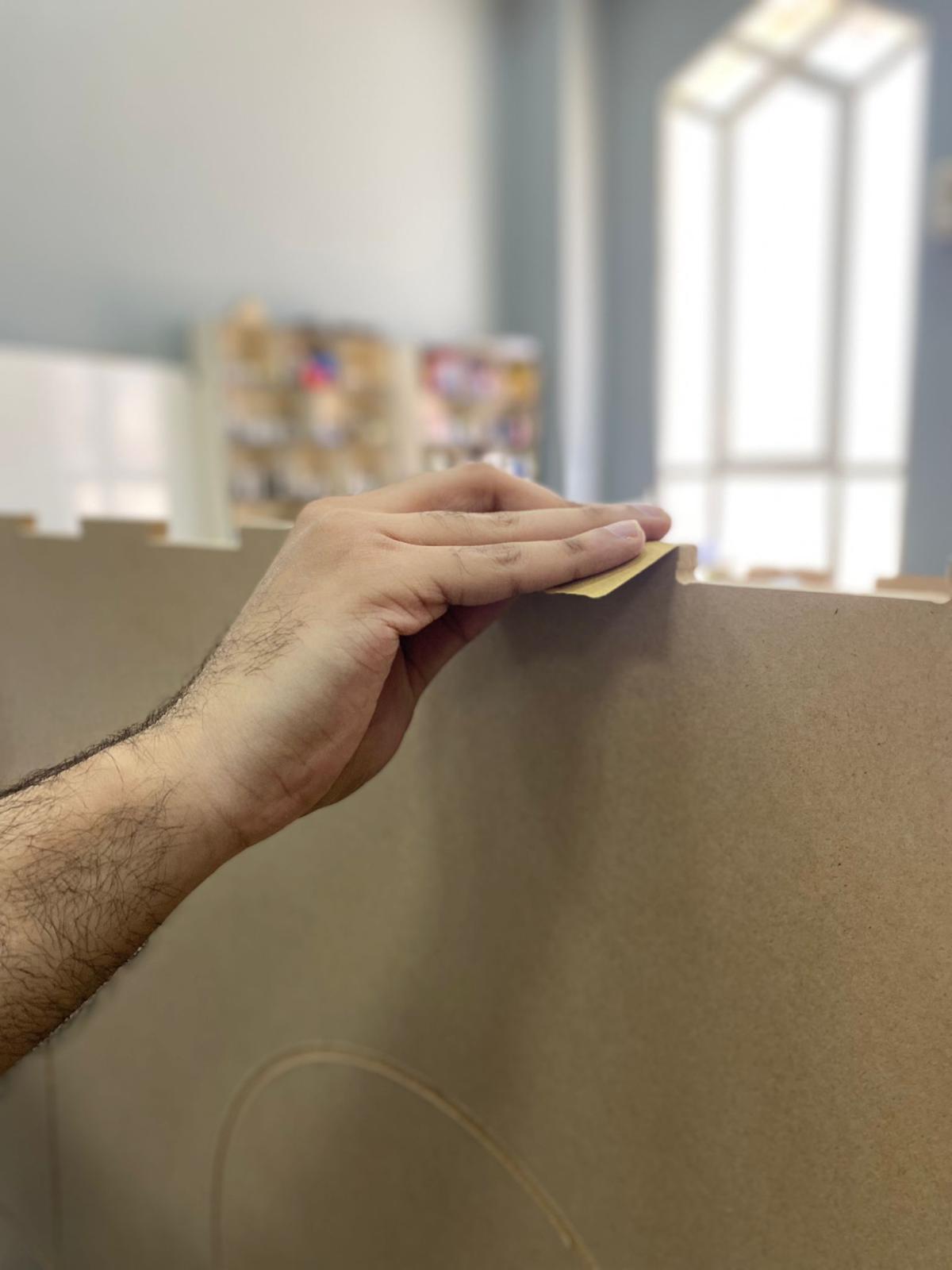
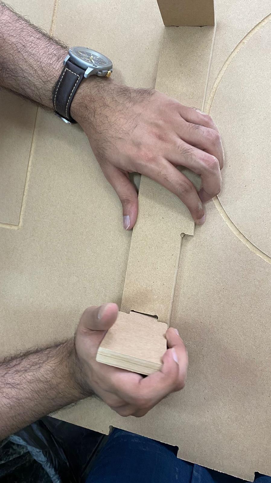
- I began with sanding the parts using the sandpaper.
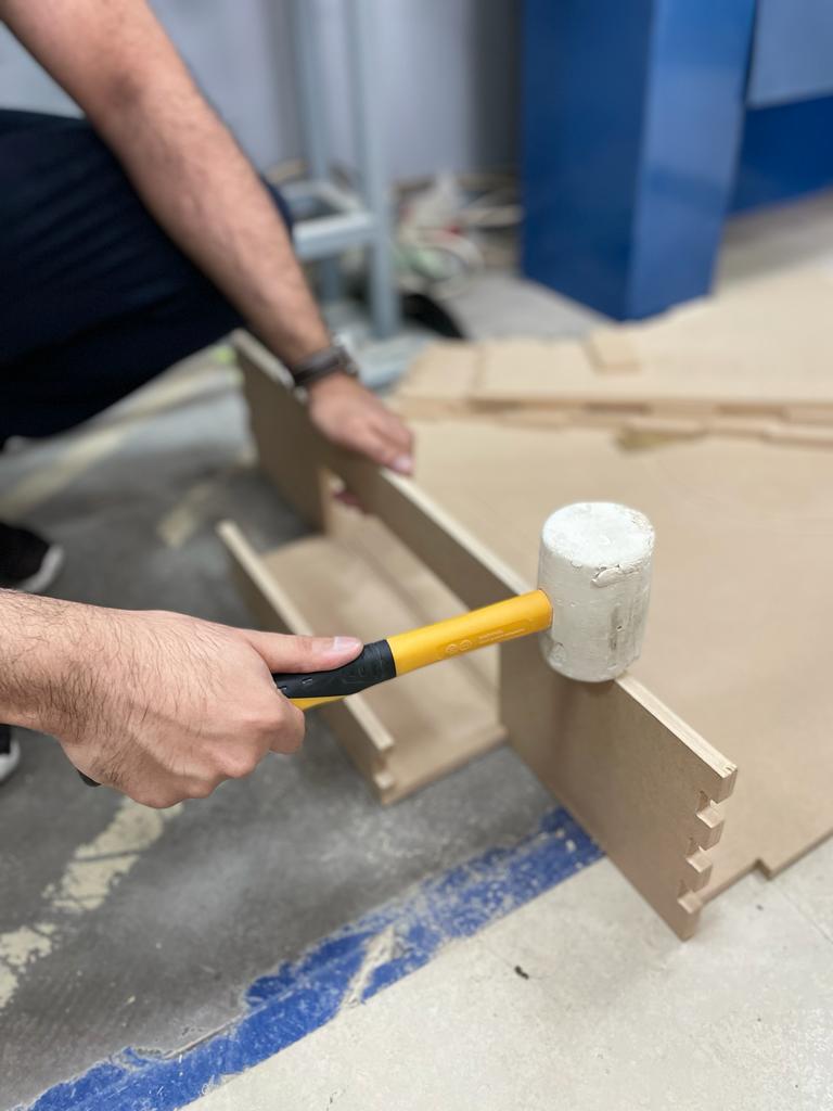
After that, I started putting the pieces together with the hammer, but some of them didn’t require it, so I just did it by hand.
Hint: The MDF material is so weak so i needed to be so gentle while using the hammer or the material will break. Also, i used a tool that helped me to fit some of the parts manually without the need of using a hammer.
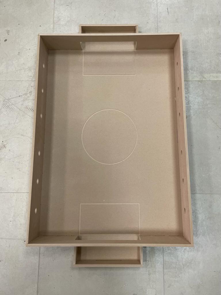
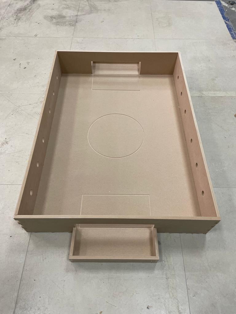
- The final result
The problems I faced during the assembling process:
-
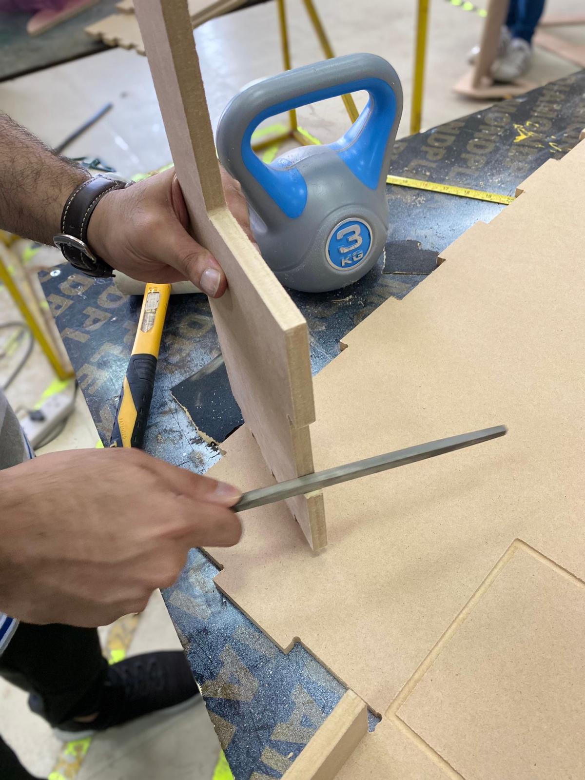
Because the MDF was weak, several of the joints were too close to get broken while using the hammer. I then overcame this issue by further sanding the joint with a tool until their size became smaller, at which point I was able to assemble them by hand without the use of a hammer. But because the larger parts have many joints and sanding them would take a lot of time, this approach only works for small parts like the goal block. For the big parts, i had to be so gentle and carful while using the hammer to avoid breaking the joints.
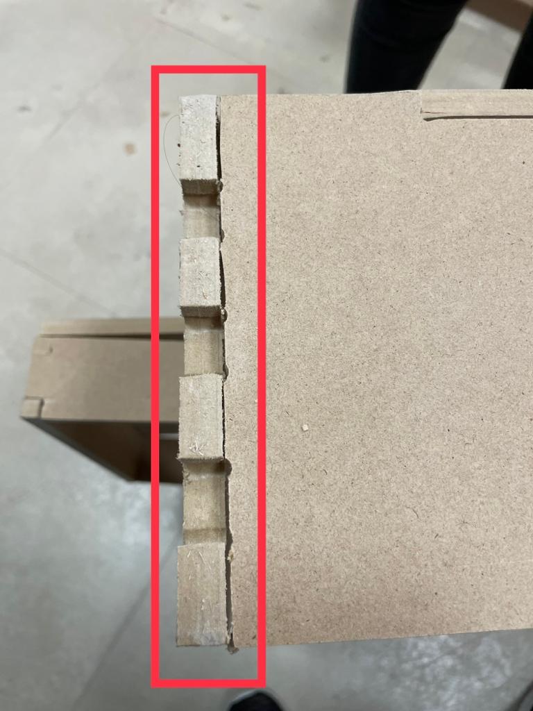
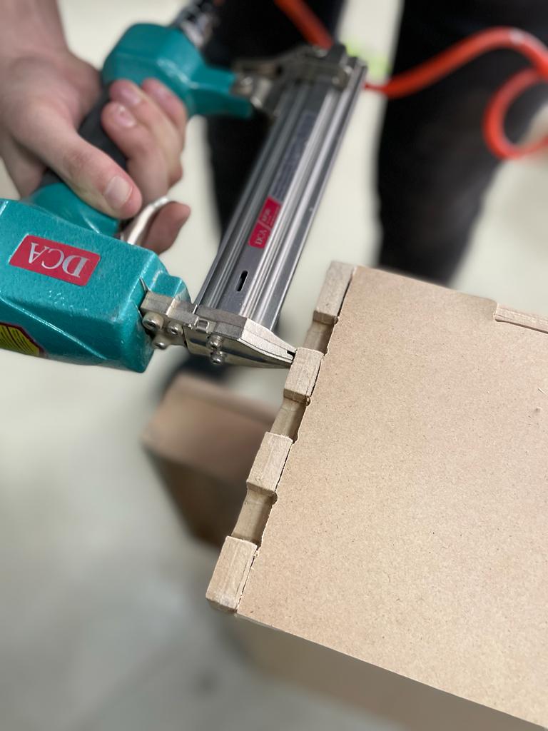
-
Another issue I ran into was that I cut the foosball’s side wall twice, which was a mistake because the front joints on both sides were actually different from one another. As a result, when I went to put them together, the joints on the left side wall were not fitting. So, I used a jigsaw to cut all the joints that were causing the issue, and then I used a stable gun to let the part be fixed with the one next to it. The outcome was satisfactory.