Week 2: Computer-Aided Design
This week we explored and familiarized ourselves with a number of different 2D and 3D softwares.
2D Design Softwares: Cuttle and Inkscape
Cuttle: an Online 2D Design Software Website
Features of Cuttle
- Simple tools, such as adding shapes like circles and rectangles.
- Modification of shapes, such as creating patterns with linear and circular repetition.
- Parametric design capabilities through creating and re-using components.
My Design on Cuttle
For my first design attempt, I first created an account on the Cuttle website and followed an easy step-by-step tutorial to learn how to use the useful tools. The tutorial showed how to execute a circular repetitive pattern design and it gave me the idea to try a mirrored symmetrical design.
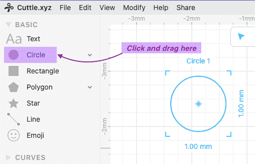
Step 1: Creating a Shape
First start by clicking on the Circle tool and drag it onto the canvas to add a circle.
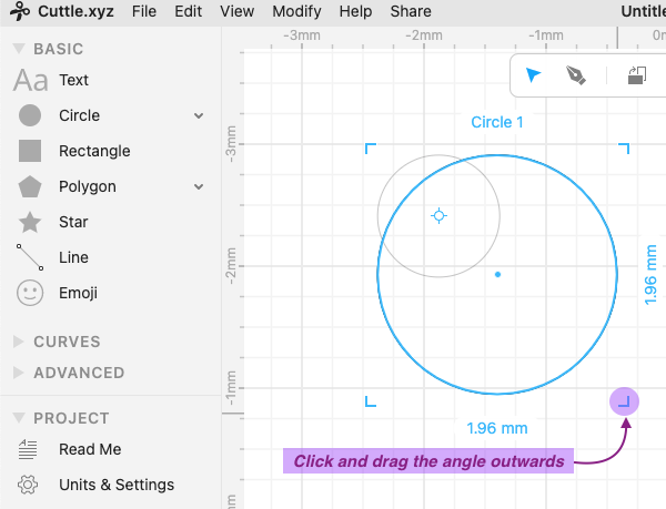
Step 2: Scaling a Shape
By clicking and dragging the angles at a corner of the shape, we can scale it to downsize or upsize it. I made my circle larger by dragging it outward.
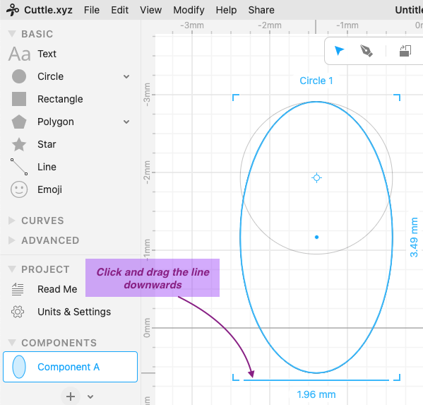
Step 3: Transforming a Basic Shape
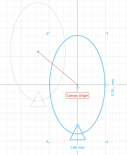
To change the shape of the circle, we can hover the mouse over one side of it until a blue line appers. By clicking and dragging the blue line on the bottom of the circle downwards to elongate, we can transform it into an oval shape.
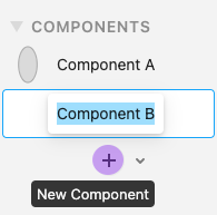
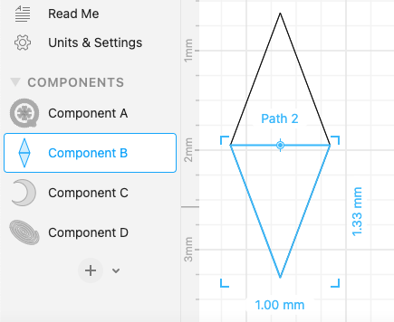
Step 4: Creating a New Component
By going to the Components category on the left-hand side of your workstation, you can click the + sign to add a component. Notice that it will open a brand new canvas for you to create the new Component B.
Info
The purpose of adding components is that it is beneficial for parametric designs. It allows us to control separate components of a single design without making the process too complex.
It’s also useful to create a component you use regularly and can be modified separately, because the modification will automatically be applied to ever instance that the component is used in the design.
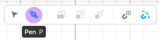
Step 5: Using the Pen Tool
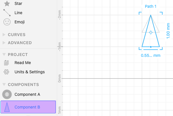
I select the Pen tool from the toolbar located in the top middle of our workstation page. The pen tool can be used to create abstract shapes or other geometric shapes that aren’t readily available in Cuttle.
I chose this tool to create a triangle by drawing three lines and connecting them at the nodes.
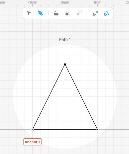
Tip
Using the grid-snapping tool (that is also found on the top toolbar) and drawing each line to meet with the squares of the grid will allow you to make a completely symmetrical shape.
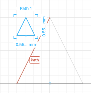
I then rescaled the triangle to my desired size.
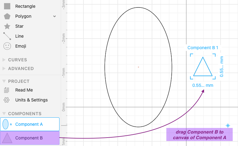
Step 6: Adding a Component to the Current Design
To add the component we just created to our original canvas that we’ll be making our design on, click and drag the Component B from Components.
I will move the triangle at the position I want it in by clicking and dragging it. Then I will select them both by clicking and dragging from one corner of the canvas to another. They will both be highlighted blue to indicate that they have been selected, so I will move it to the origin to prepare for my next step.
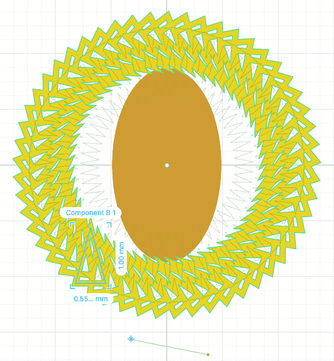
Step 7: Modifying a Shape to Create a Rotational Repetition Design Pattern
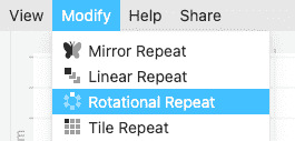
While selecting only the triangle (Component B), select the Modify menu on the top of the page, then click on Rotational Repeat. This will repeat the same trangle shape a set number of times while rotating around the axis that you choose. I moved my shapes to the origin in the step before for it to rotate around the origin.
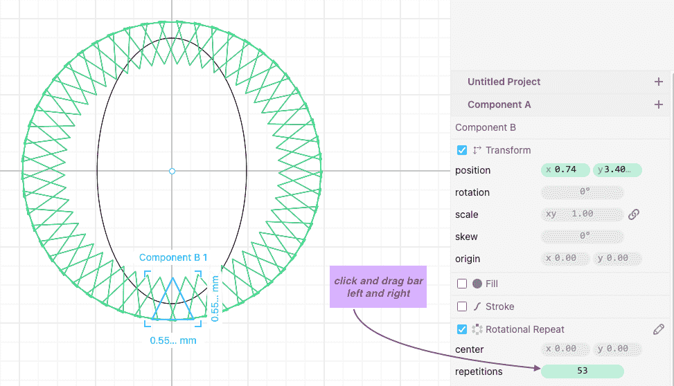
On the right-hand side of the workstation page, there is a panel that shows different features we can control of the Rotational Repeat, such as the number of repetitions and the center it will rotate around. I played around with value until I got the pattern I wanted. We can do this by clicking and dragging on the bar (highlighted in green) from left to right to decrease or increase the repetions.
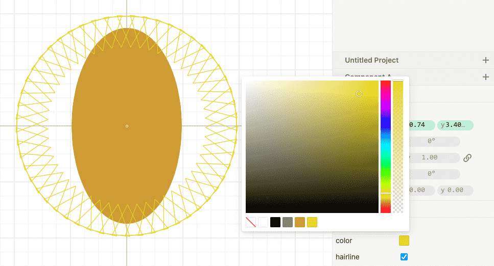
Step 8: Change the Color of Different Shapes
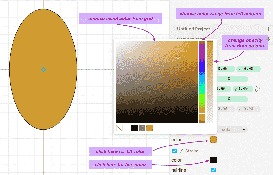
To change the color of each individual shape, notice that on the left-hand panel, you have a list of all the components on the current canvas that you’re working on. I clicked on Component A to select the oval. At the bottom of the same left-hand panel is a part we can modify called Fill. Ticking the box allows you to access the square that you then click on to select the color you want to fill the shape with.
You can click and drag around the color grid to see the shade of the color of the shape change. If you want to switch between different colors, click and drag the bar on the left colomn. If you want to change the opacity of the color (how transparent it is), click and drag on the right colomn.
To change the color of a line stroke, we can use the same steps mentioned above. I repeated this process for Component B.
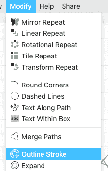
Step 9: Adding an Outline Stroke
Adding an outline stroke allows you to add width to line shapes. Find this by going to the Modify menu and clicking on Outline Stroke.
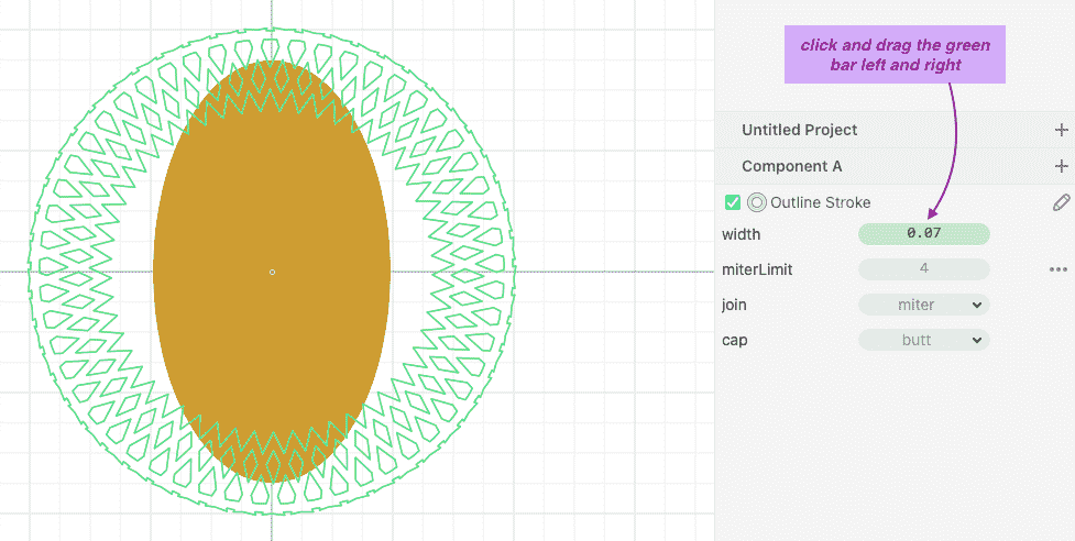
We can control the width of the outline stroke on the left panel by clicking and dragging on the bar (highlighted in green) from left to right to decrease or increase the width.
Step 10: Modifying Existing Components Separately to Change the Current Design
Info
This step is an example of the benefits of parametric design.
The benefit of us creating a separate Component B is that we can go into that separate isolated canvas at any time to modify it. I do this by clicking on Component B in Components and making the shape taller by clicking and dragging it.
If we go back to the original design in Component A, we can see the result of changing Component B. The changes that we made so far are still applied, but we can go back and change any aspect of the design we want to. I also decided to transform the shape by rotating it. We can do this by hovering the mouse near the angle on the corner until an arrow appears. Clicking and dragging the arrow either clockwise or anti-clockwise will rotate the shape. Since we used Rotational Repeat, the rotation will be applied to all the shapes.
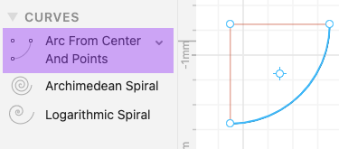
Step 11: Creating a Shape with Curves
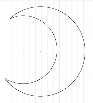
I added a new Component C to open a new canvas as we’ve done before. On the right panel is a Curves section. If we expand it we can see different options. I selected the Arc From Center And Points by clicking and dragging it to the canvas.
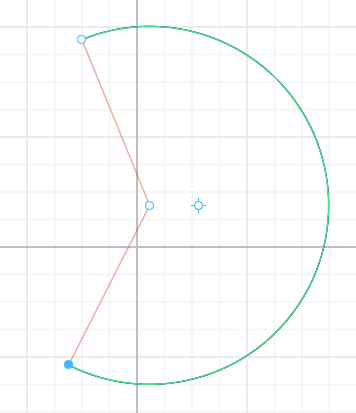
By clicking and dragging the different nodes, I made a circular curve to the shape and size that I wanted.
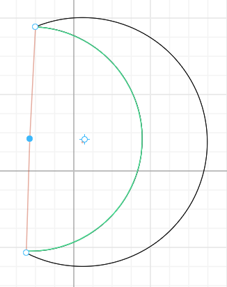
I then clicked and dragged and resized another curve of the same type and adjusted the shape to how I wanted it to form a half moon shape.
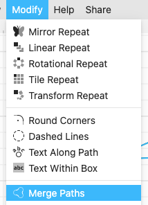
To join the two curves together, I went to Modify > Merge Paths that connected the curves together.
Now that they were connected as one shape, I adjusted the shape to what I wanted.
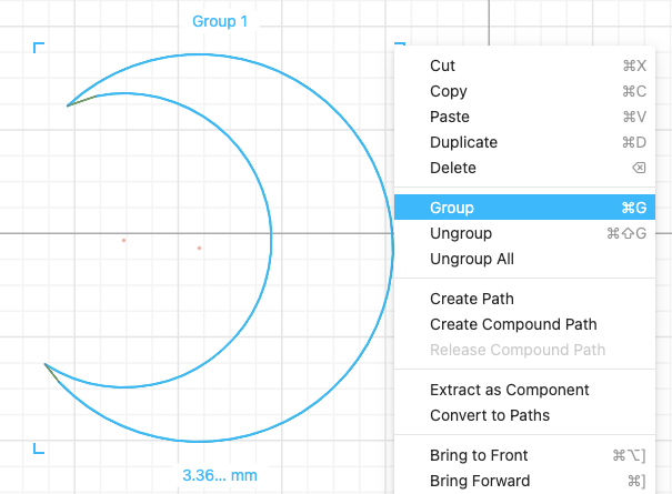
I then selected all and grouped them together. This will make it into a solid shape that we can then fill to color it in.
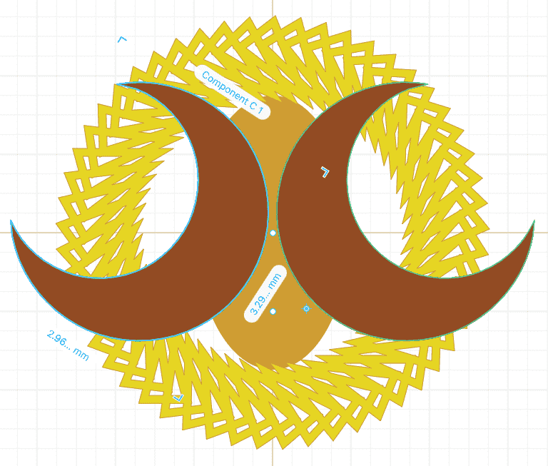
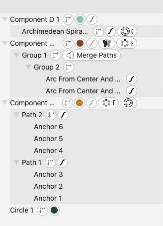
Step 12: Mirroring Shapes
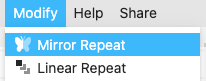
To mirror a shape and have its duplicated reflection, select the shape you want to mirror and go to Modify > Mirror Repeat. I did this with Component C to have two moons back to back.
We can see the result below where I also rotated the shape to my desired position.
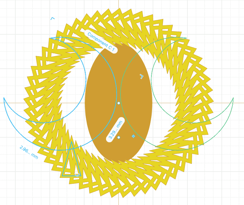
I then coloured in the shape.
Note
Notice that any change in appearance I do to Component C1 (left), which is the original shape and not the mirrored one, translates to the mirrored shape Component C2 (right).
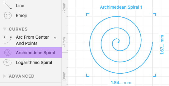
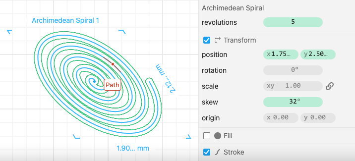
Step 13: Creating a Spiral Shape and Modifying It
I added a new Component D and went to Curves, then clicked and dragged the Archimedean Spiral to the canvas.
I then went to Modify > Outline Stroke and adjusted the width of the outline to 0.13 where I preferred it.
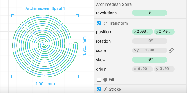
You can also transform shapes by skewing them. To do this, look for skew on the right side panel and drag the bar (highlighted in green) left or right to the skew angle you want.
Step 14: Playing Around With and Finalizing the Design
At the current stage, I do not want to add any more components to my design, but I want to play around with the composition of the design until I am satisfied with it. I can do this by repeating actions that were discussed in previous steps.
I decided to modify Component B by duplicating it and aligning them together as if they are reflecting each other to create a more complex shape for my design. As we discussed before, this change will translate to and appear in our original design.
After rotating and re-scaling each of the different shapes to the appearance I wanted, and also changing some of the colors to compliment each other more, my design was complete.

We can see that throughout the creation of our design, each of our actions and modifications have been documented by Cuttle as a timeline. This is useful for keeping track of the different steps you completed, or to go back and change one of the previously done modifications. This is available on the right side panel as a drop-down list, which can be expanded to show more information.
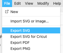
Step 15: Exporting the Design
We can export Cuttle designs as SVG files or other formats. Notice that it also says Import SVG, which means that our SVG files will be possible to re-open in Cuttle.
You can download my SVG file for my design here.
Note
You do not need to save your project as you work in Cuttle, because the website will periodically autosave your project for you. It will be available for you online to re-open and continue editing.
Inkscape: a Free Open-Source Application for Digital Art
Features of Inkscape
- Great open-source alternative to Photoshop for all your image-editing and digital art needs!
- Used to create vector images, primarily in SVG format
- Can open and edit DXF files on it
My Design on Inkscape
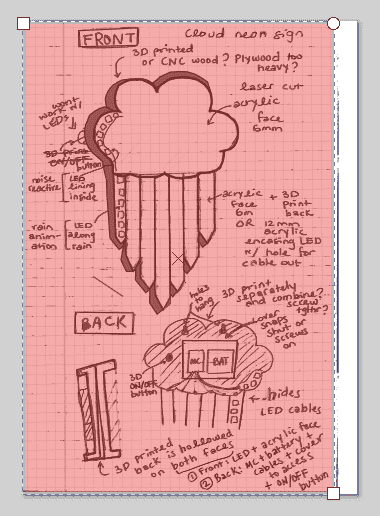
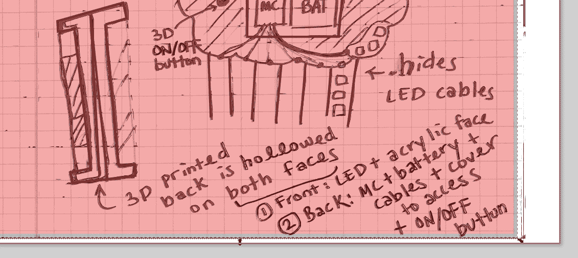
I decided to use Inkscape as my primary way to trace and edit my hand-drawn sketches of designs I’ve pre-planned before I started modelling them. This sketch I’m about to work on is the sketch for my final project idea! Using Inkscape will help me polish it and make it clear enough to add to my final project page!
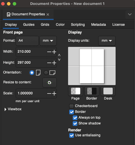
Step 1: Importing the Sketch
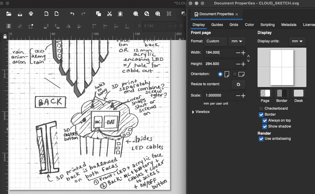
First, the moment we open up Inkscape, we can adjust the document size by navigating to File > Document Properties:
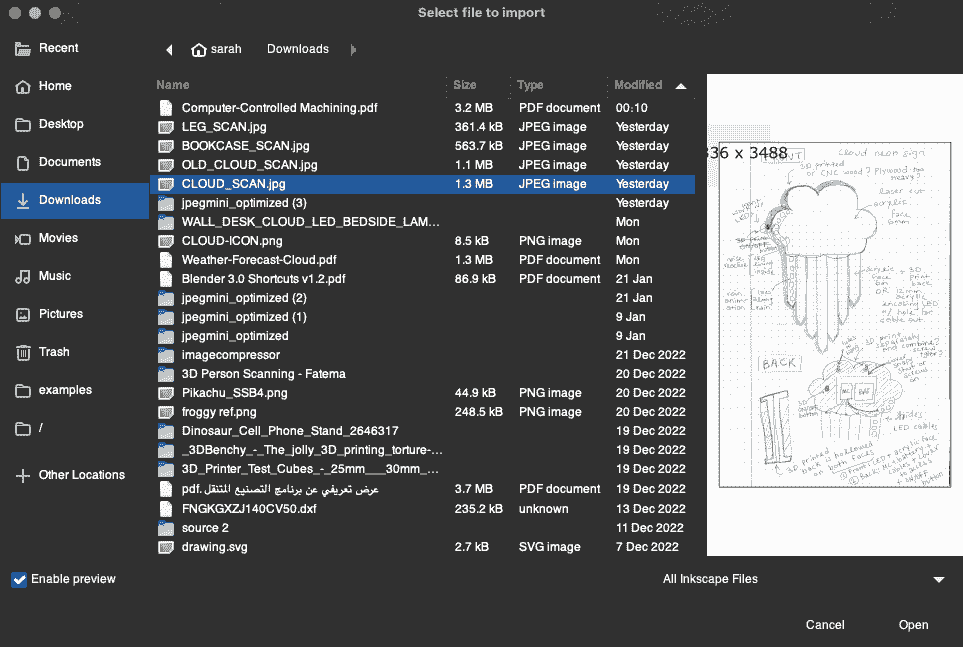
Next, I imported the sketch that I scanned on my printer:
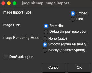
As soon as you import the image, you get options for how it should be imported into Inkscape. I want to ensure the quality stays intact since it is hand-drawn, so I select the Smooth Image Rendering Mode:
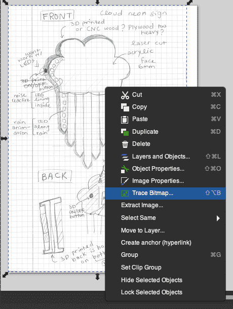
Step 2: Tracing and Enhancing the Sketch
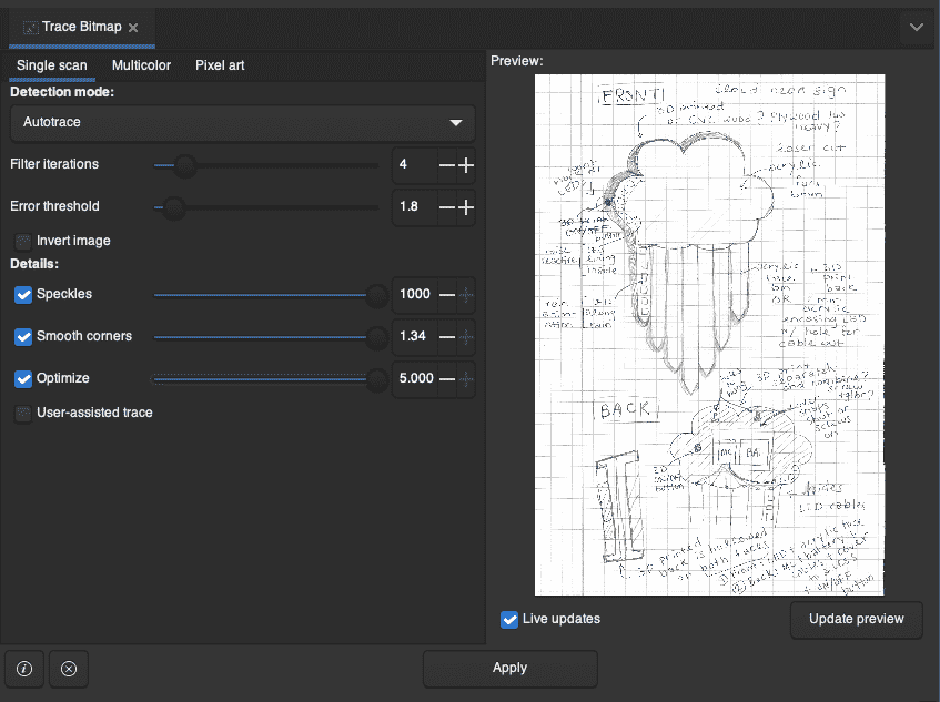
Once the imported sketch is added to my canvas, I can now select it, then righ-click and click on Trace Bitmap:
Choosing this option will now open up a panel on the righ-hand side of the workspace with options for how to trace out the bitmap and controlling certain properties. The good thing about this feature on Inkspace is that it allows for live updates, which means that while you’re adjusting any of these parameters, such as the Detection Mode, it will automatically update with a very short delay to show you what these changes will look like.
To trace out my hand-drawn sketch, since the lines and the shading were kind of irregular and not consistently opaque, as they were done with pencil, I wanted to lay the traced bitmap over the existing sketch to reinforce and define the lines, but keep it looking like a sketch.
For the first round of bitmap tracing, I used the Edge Detection Mode, which helped clearly define the letters of all the labels and notes I had for annotating the sketch, but the actual sketch drawings weren’t fully defined yet. So next, I started another bitmap trace to create multiple layers of them, and used Autotrace Mode, which was the best way to get as many of the drawings to appear as clear as possible.
Step 3: Drawing Over the Sketch
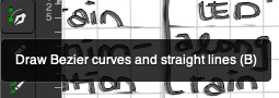
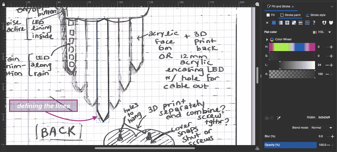
To further define my drawings, since they were still faint in certain parts, I used the Draw tool to draw Bezier curves and straight lines for the straight lines and the curved lines in my drawing.
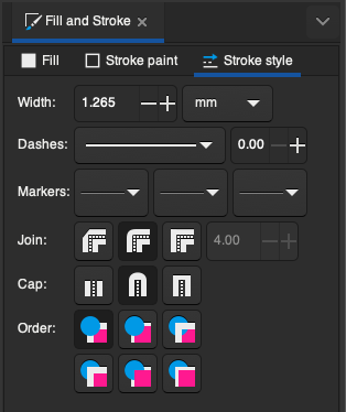
As we saw with the Bitmap Trace tool, the Draw tool also opens up a panel for editing different things such as Stroke paint, which is the colour of the lines, and Stroke style which lets you pick the width and the line type and other features.
For the Stroke paint, in order for it to match my drawing, I used the eyedropper tool to pick out the color of the lines in my drawing. This way, anything we draw over it will blend in almost seamlessly. I’ll also be using the Fill for drawing over the shading later on.
This is what the drawing looks like before I start drawing over it. We can see that the straight lines are almost completely faded and undefined, so I’ll start there.
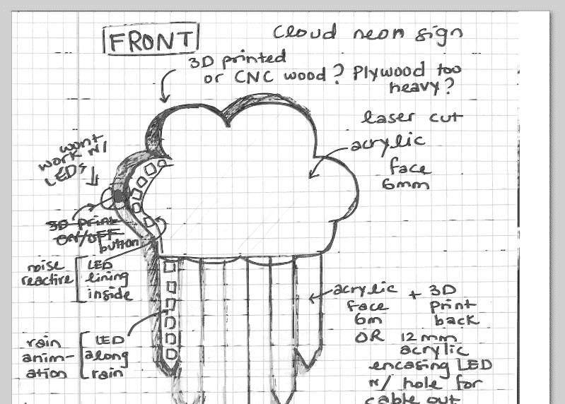
I start out by defining the first line to see the difference it makes, and we can see that the color and width I’ve chosen blend in and make the drawing more legible.
I then draw over the rest of the straight lines. I further go on to define the shaded parts on the underside of them. To do this, we have to close the loop of lines to create a self-contained shape in the form of where you want the shading to be. This way, we can use Fill to fill in the shading colour we want to use. You can see this on the panel on the right-hand side:
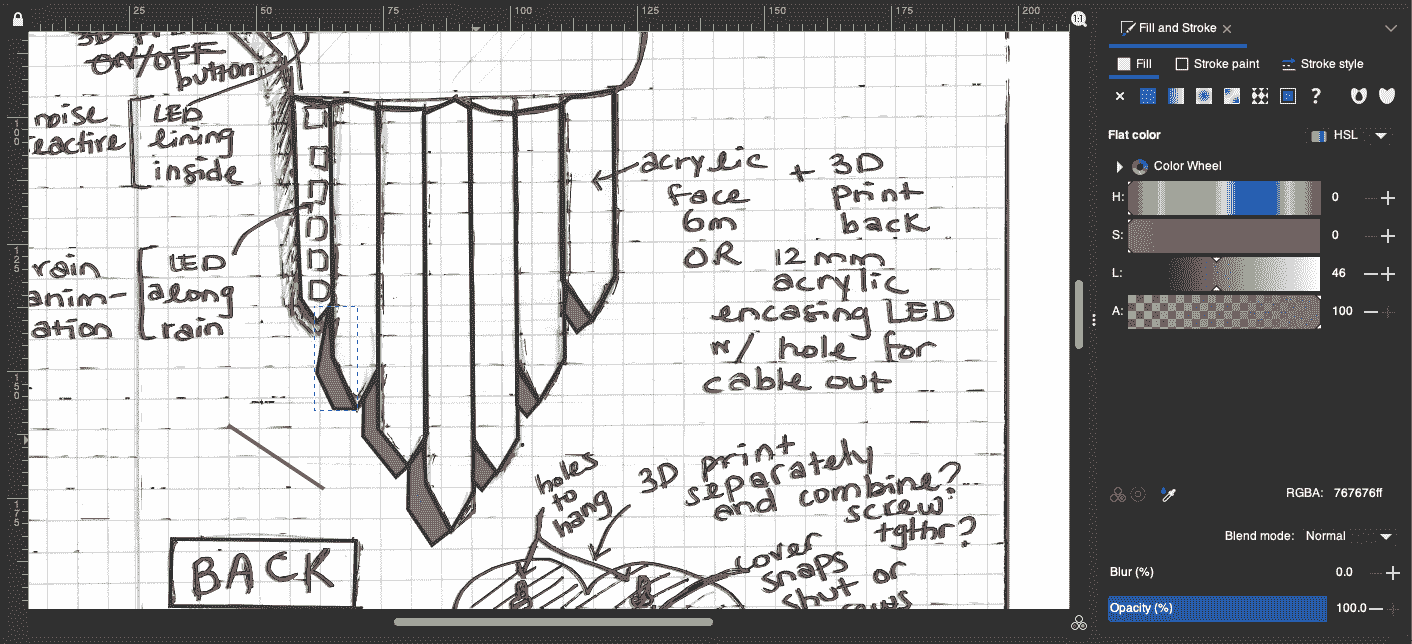
Next, I can go onto define the curved lines, as well as add shading to them. You’ll see in the next photo, I decided to make the width of the lines thicker in Stroke style to make them clearer.
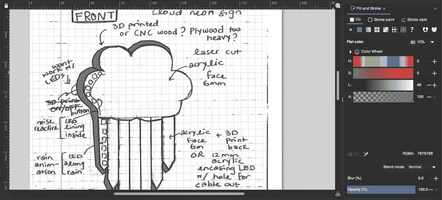
After further drawing across the sketch, and once I am satisfied with how it looks, I’ll then select all by clicking CTRL + A (or CMD + A in my case), then right-click and choose Group to create one object of the image with all the layers of editing we’ve done.
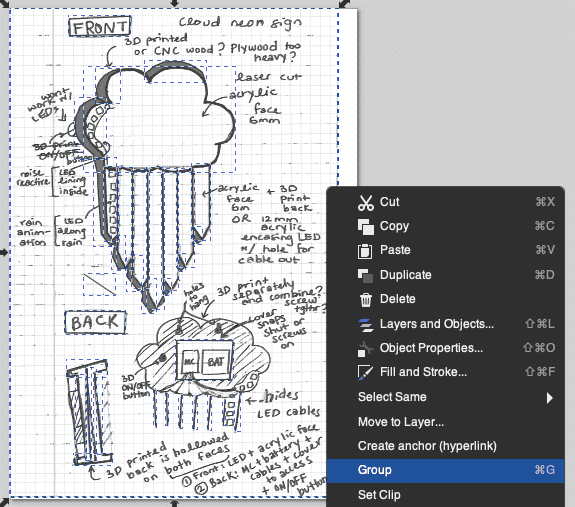
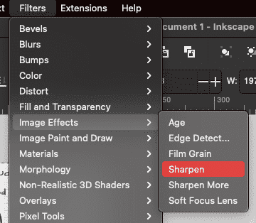
I then add the last finishing touch by adding a Sharpen Filter to the image to make it even clearer by navigating to Filters > Image Effects > Sharpen.
Step 4: Cropping the Sketch
My sketch is almost done, the last thing I want to do is crop out the lines that were caused by the scanning process to give it a cleaner finish.
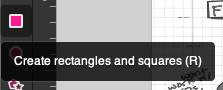
To do this, I select the tool to Create rectangles and squares:
I then draw a rectangle over the general area of what I want to keep of my sketch. This doesn’t have to be perfect, because we’ll then switch to the Select tool (hotkey S) to resize the rectangle to our needs.
To make this easier for myself to see the sketch and decide how much I want to crop off, I choose a Fill colour for the rectangle and lower its opacity enough for me to see the sketch underneath.
Using the Select tool, I can now zoom into the edges of the sketch and drag the rectangle to the exact position I want to crop it at.
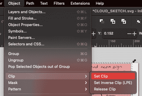
Once I am done doing this, I will then select the sketch image and the rectangle (or just select all), then navigate to Object > Clip > Set Clip. This will make the sketch take on the shape of the rectangle on top of it, effectively cropping out the parts we don’t want to keep.
The good thing about using the Clip object mask for this cropping process is that I can easily choose to uncrop it and revert it back to the original image. To do this, simply navigate to Object > Clip > Release Clip.
Next, as the final step in the cropping process, I will resize the document as we did before by going to File > Document Properties so that it fits the exact size of my sketch.
Step 5: Exporting the Sketch
The export file type we will be using is SVG, to do this, navigate to File > Export and rename and save it to the appropriate folder locally. This type of file can easily be imported into other softwares, including the 3D softwares we’ll be exploring after this.
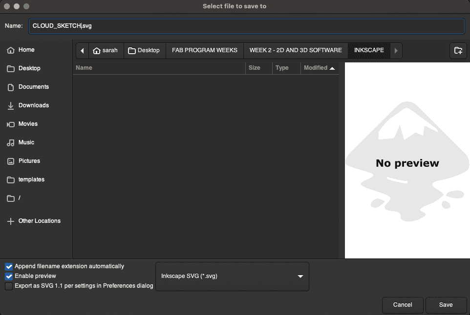
You can download my SVG file for my sketch design here.
BONUS: Editing DXF Files
Another crucial benefit of Inkscape is that you can open up DXF files on it. These are files that, as we’ll see in the 3D Softwares section next, contain the 2D sketch for the faces of our 3D designs.
This example is a DXF file for my Week 5: Computer-Controlled Machining project. We’ll go into that more when we get to that section, but the important thing to note is that when using machines that cut 2D designs, we must use 2D DXF files to give them that information in order to fabricate our designs.
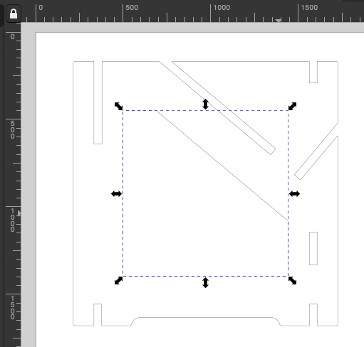
This was my design, which looks okay, but there was a problem during exporting that is not visible until I try selecting it on Inkscape.
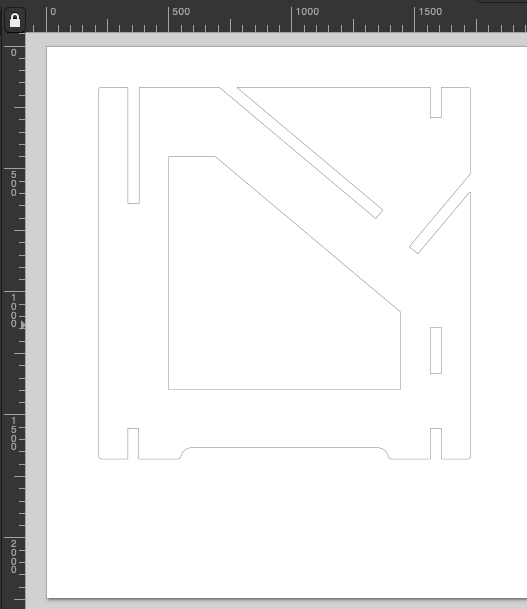
Once I try selecting it, I can see that the entire design is not connected together as one object. We can see this here because I am able to select the shape in the middle separately from the outer square shape.
Tip
To avoid this issue, make sure you Project all sketch elements you want to include in Fusion 360 before saving as DXF.
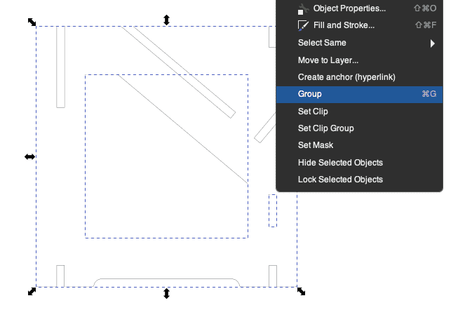
To resolve this issue, I select all the components of my sketch, making sure that they haven’t been moved out of place, then right-click and choose Group to combine them into one object.
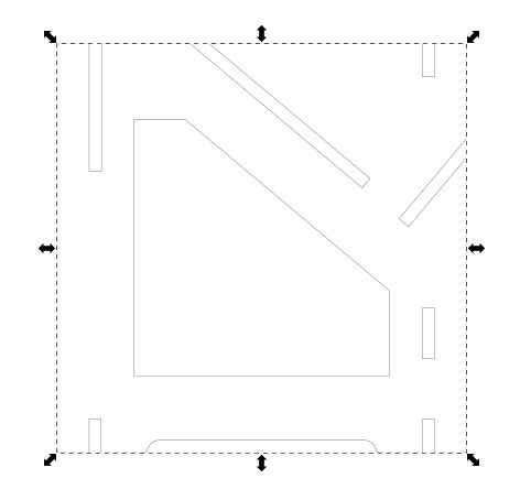
We can now see that when I select all, I am only selecting one object, so I know that the entire thing has been combined correctly, and now it will be ready for me to download to my machine! See Week 5: Computer-Controlled Machining for more details about this design and the final product!
Tip
It is best practice to always open up DXF files on Inkscape to double-check these minor issues before you can move forward!
3D Design Softwares: Fusion 360 and Blender
Fusion 360: a Subscription-Based 3D Modelling Software
Features of Fusion 360
- 2D Sketching and parametric design capabilities with components.
- 3D Modelling from 2D sketches that allows for multiple ways of transforming and manipulating solid 3D material.
- Files can be exported and uploaded to Sketchfab for an interactive display.
Tip
To have full free range of motion while moving around your 3D model in Fusion 360, you can use your mouse to Orbit by clicking on Shift + Scroll Wheel and moving your mouse around to move alone all axes. You can also Pan by holding the Scroll Wheel and moving your mouse around. Scrolling will zoom the plane in and out.
My Design on Fusion 360
For my design, I followed a helpful tutorial to learn how to use Fusion 360 correctly, as the learning curve was steep and I struggled with understanding the different steps and components of the 3D design.
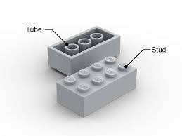
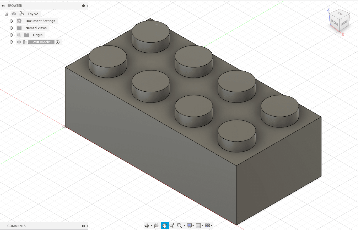
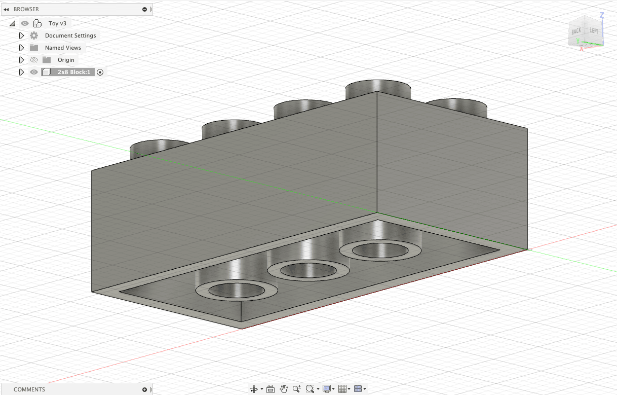
My design was a 3D model of a toy block modelled after a LEGO brick, as shown below.
Step 1: Creating the Block
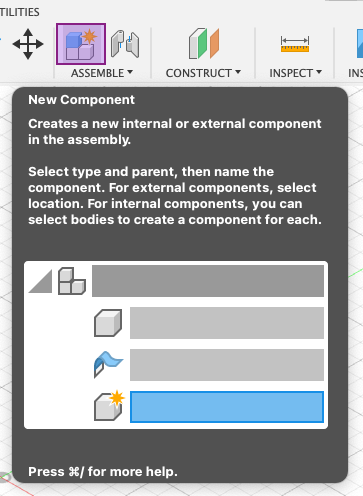
After creating a new project, we will start by creating a new component in the form of our toy block. We do this by selecting New Component from Assemble.
Tip
Getting into the habit of creating components for each model you make is good for parametric design.
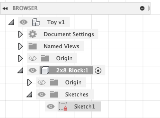
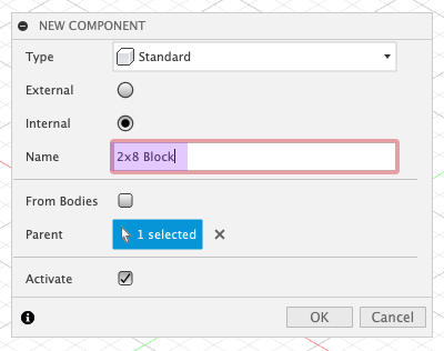
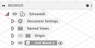
This will prompt us to name our component, which we will call 2x8 Block, representing its dimensions.
On the left side of the page, we can see that our component has been added to our project files.
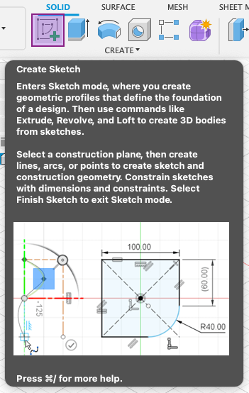
Next, we will start our model by first sketching it out. This will help us establish both the shape and dimensions of it.
Tip
All tools in Fusion 360 show a description of its use when you hover your mouse over their icon.
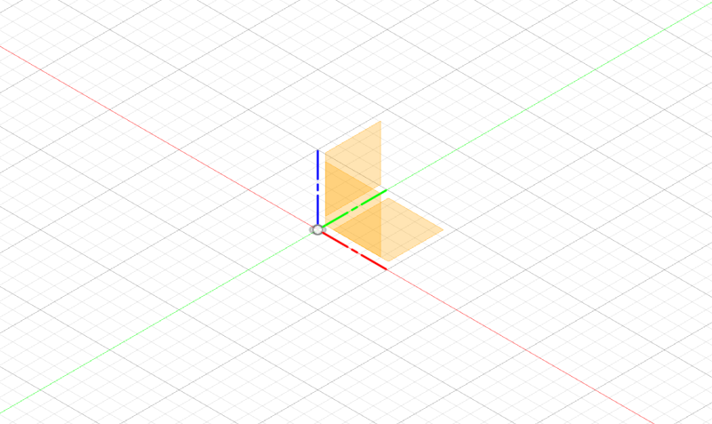
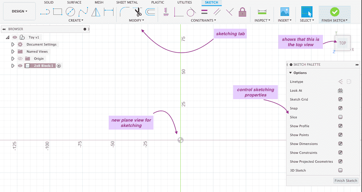
After clicking Create Sketch we will see this, which is prompting us to choose which 2D plane to draw our sketch on.
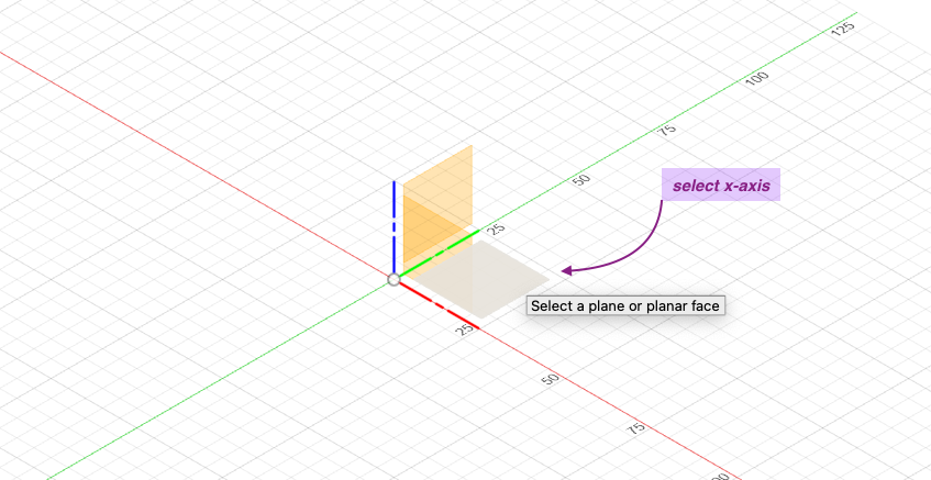
Since our block will be set down on a flat surface and will have a rectangular shape, we will choose the X plane.
Once we do this, our view will change to the Sketch tab, where we will have new tools, an axis with measurements shown in millimeters, a cube that shows us the orientation that we are on (which shows that we are looking at the top view), and a sketch palette.
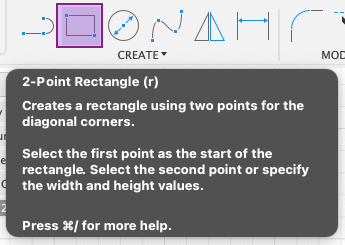
We will start by creating a rectangle shape by selecting 2-Point Rectangle.
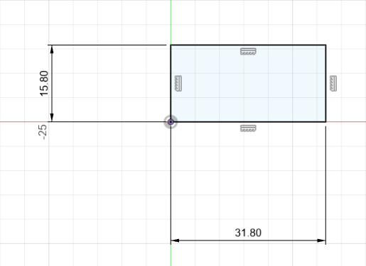
We will then draw a rectangle starting from the origin on the axis by clicking and dragging out. We can set the number of the width by typing them and hitting TAB to lock the measurement and switch to the length and repeat the step.
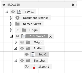
We can now see that our sketch has been added to our files.
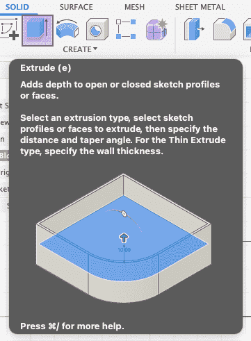
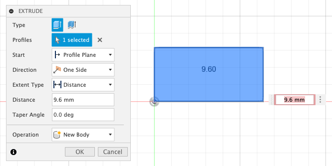
Next, to turn our sketch into a 3D shape, we switch to the Solid tab and select Extrude.
We then select our rectangle sketch as the shape we want to extrude and set the distance for how much we want the thickness of the block to be.
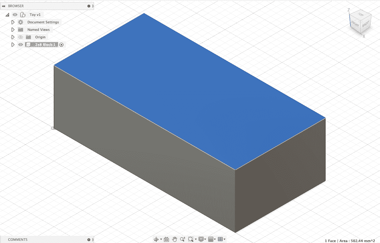
We can now see that our sketch has been used to make a 3D shape through the addition of a body to our files.
Step 2: Creating the Studs
We can see how our block looks like now. To add the studs, or the 3D circles on the top surface of the block, we will need to create a sketch on the top surface of the block.
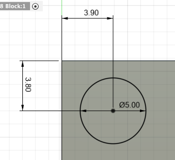
In our Sketch tab, we will use the Center Diameter Circle tool to sketch our studs.
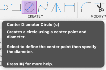
By clicking and dragging on top of our first rectangle sketch, we can form a circle and then set the measurement in the same way as before by typing in the value.
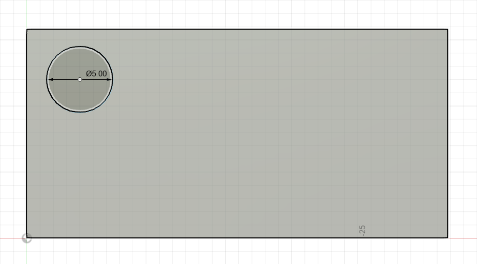
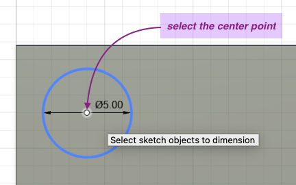
In the next steps, we will need to create more studs by duplicating our initial sketch. We will first use the Sketch Dimension tool to set the distance that we want the sketch to maintain between itself and the boundaries of our rectangle sketch.
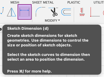
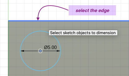
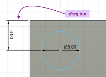
First select the center point of the circle, then select the top edge of the rectangle. This will set the dimension on the side that is next to it and we can set the value by typing it in.
We repeat the steps on the other side, but selecting the left edge instead of the top edge.
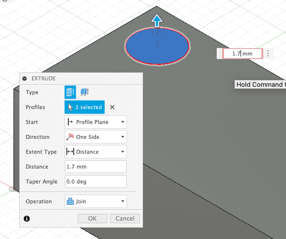
We can now create a 3D shape of the stud from our sketch by going to Solid > Extrude and setting the distance or the thickness of the stud.
Note
Notice that the operation says Join, this means that the 3D body of the stud that we are making will be joined with the 3D body of the block to form one connected 3D body.
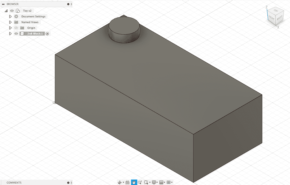
The result will look like this, with both the stud and the block joined together as one 3D body.
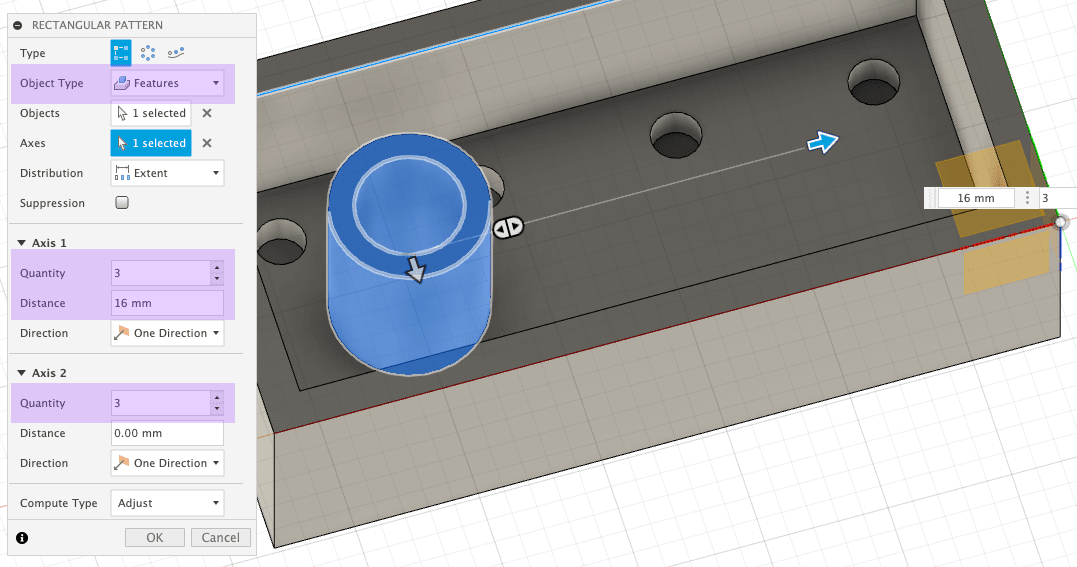
To create the remaining studs, we will use the Rectangular Pattern tool to duplicate the initial stud we made.
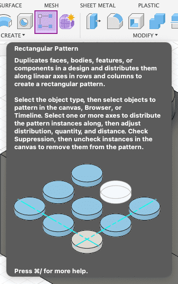
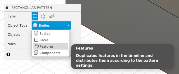
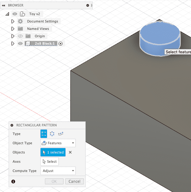
We will have a Rectangular Pattern toolbar to control the operation we want to do. First start by clicking on Features in Object Type, since we will not be duplicating the whole body since that would include the block. The stud is considered a feature of the body. Then we will select the stud for the Objects.
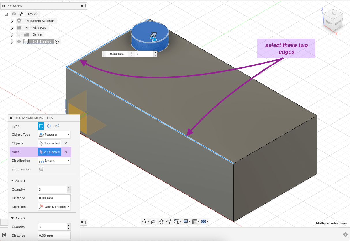
After this, we will select the Axes and choose the axes we want our pattern to follow. We will select two sides to follow the width and the length of the block.
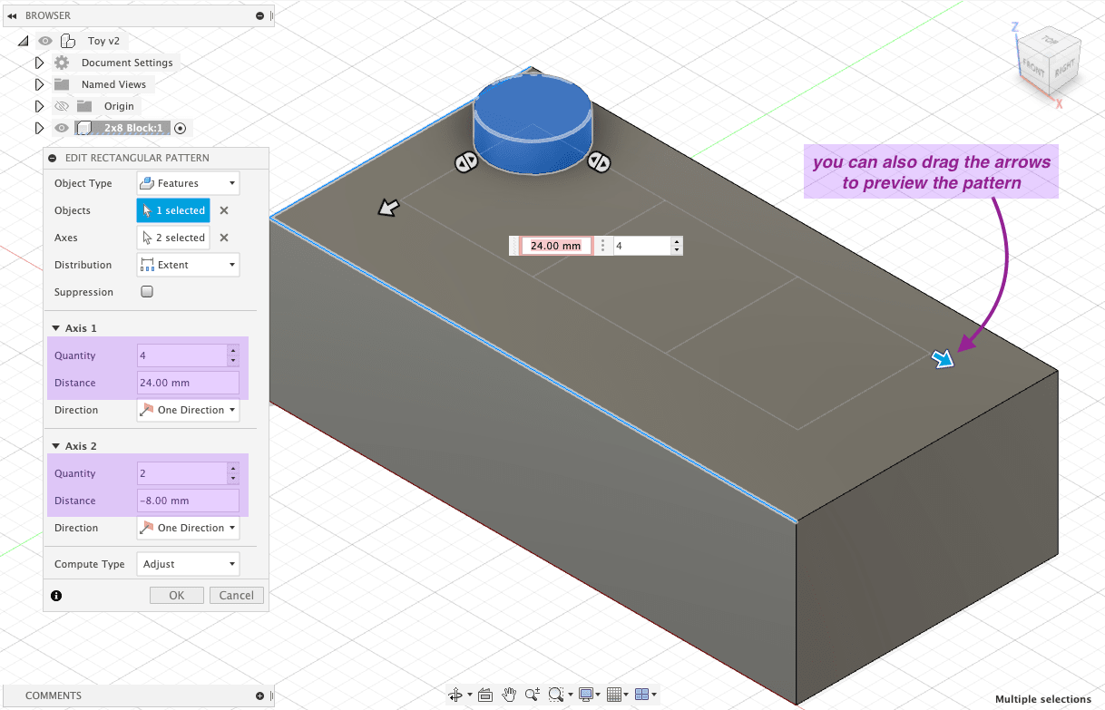
Referencing the pattern of the studs on the toy block picture, we can see that there are 2 columns and 4 rows of studs, making them 8 studs in total. Knowing this, we will select the quantity of Axis 1 as 4 for lengthwise and Axis 2 as 2 for widthwise.
The result after using the Rectangular Pattern tool has created all the studs for us and now the top part of the toy block is finished.
Step 3: Creating the Tubes
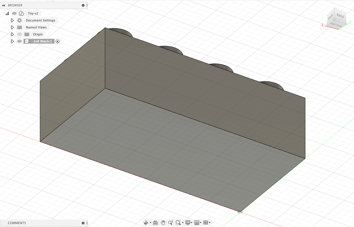
Next, we move onto the bottom part of the toy block where it is hollowed out and we have three tubes.
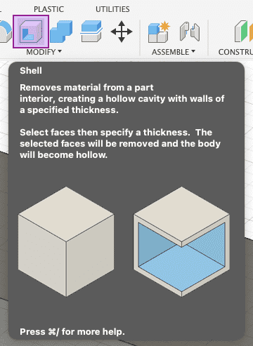
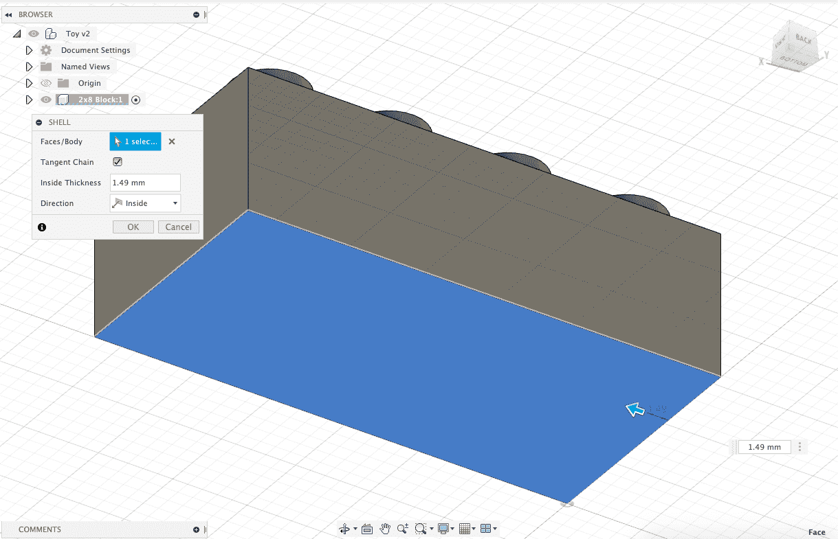
To first hollow out the bottom, we will select Solid > Shell which will create a hollow cavity in the body of our block from the bottom face.
We then select the bottom face and set the desired thickness that will border the cavity.
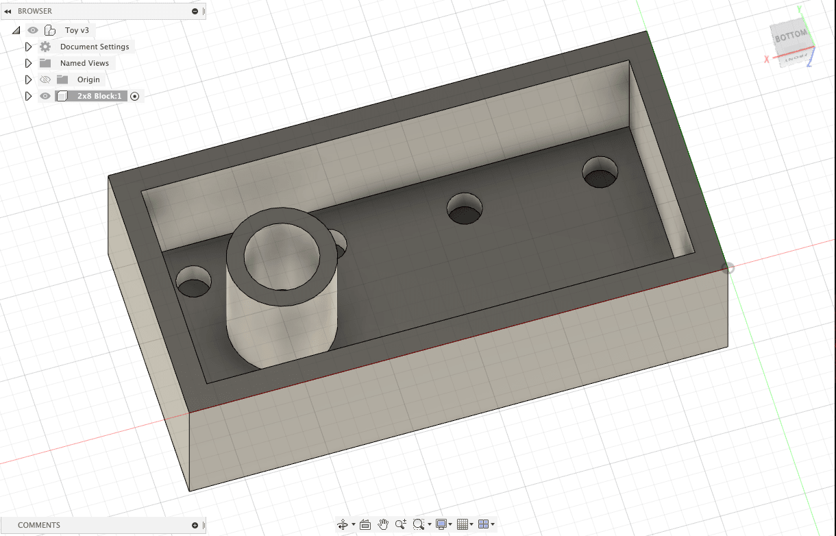
This is the result of the bottom after using the Shell tool.
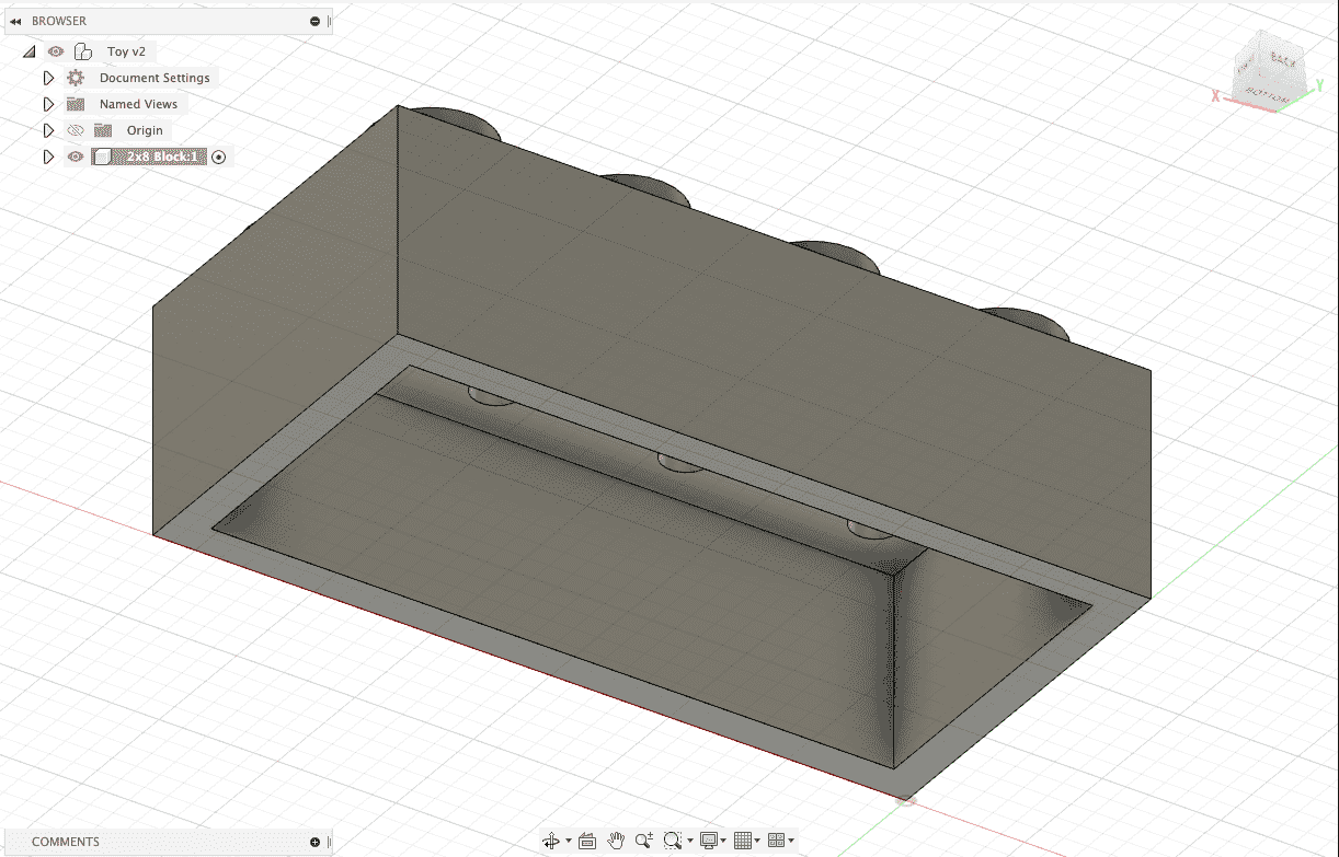
We can now switch our view to look completely into the bottom of the block. We can see that there are markers where our studs were joined with the block. By right-clicking we can create a sketch on this plane.
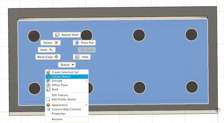
To create the tubes, we first must establish the position of the initial tube we will create, so we can later on repeat the steps we did with duplicating the studs with Rectangular Pattern tool with the tubes. To do this, we will first need to figure out the midpoint between each grid of the four studs so that the design of the tubes is symmetrical. We will do this by first creating a construction line.
To do this, we will select the Line tool from the Sketch tab.
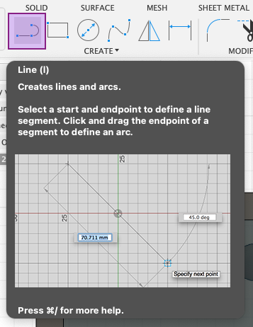
To draw our construction line, we must first select the Construction linetype, otherwise it will sketch a regular line. Then, we will click on the center of one of the circles on the leftmost grid of 4 studs.
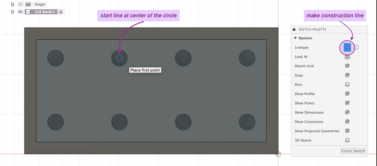
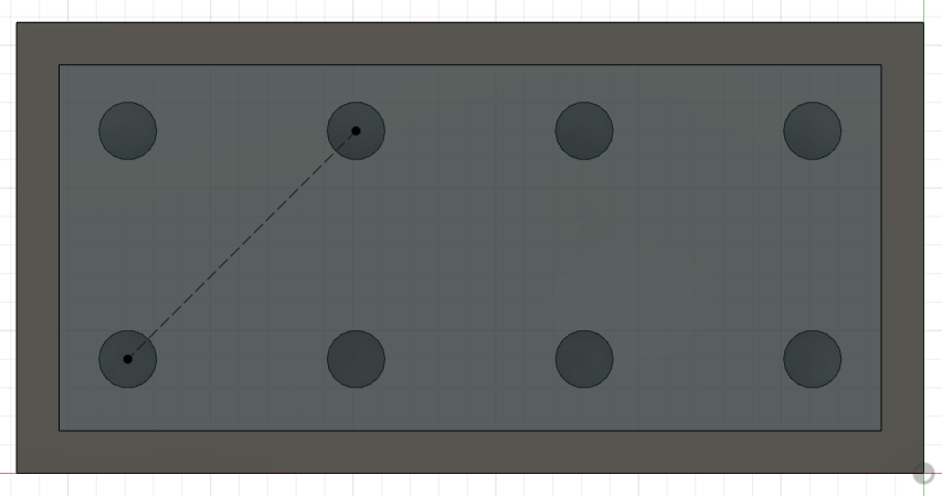
Then, we will draw a line diagonally to connect it with the center of the circle across from it on the grid.
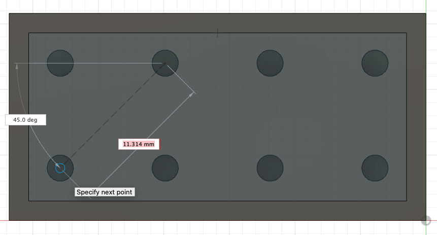
This creates our construction line to start our sketch.
Then, we will switch to the Center Diameter Circle tool (make sure you de-select the construction linetype) to sketch our tubes. Hovering the mouse over the construction line, we can find the point where a triangle symbol is visible. This represents the midpoint of the studs in this grid.
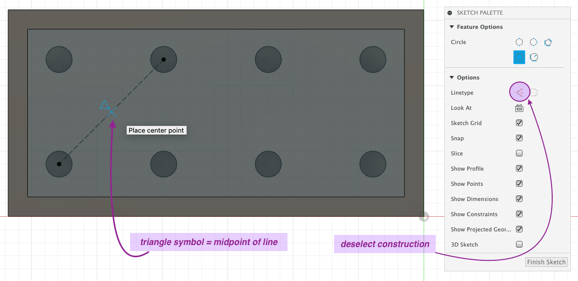
Sketching a circle from the midpoint that we established, we can now type in the size of it.
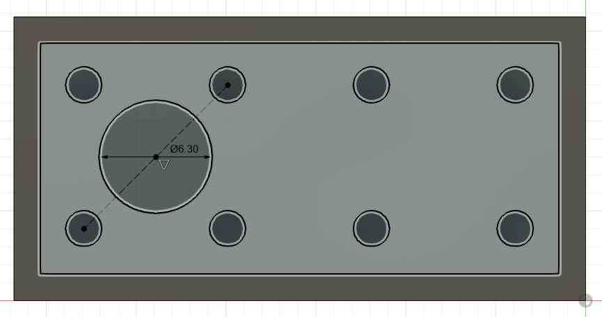
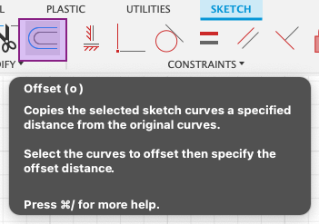
To create the actual shape of the tube, we will use the Offset tool that will copy the circle.
We will set the Offset position to the thickness of the tube and click on Flip. This will allow us to make a sketch that will already be the exact shape of the tube when we later extrude it.
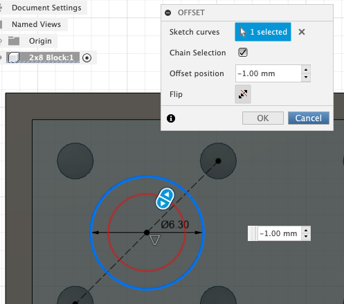
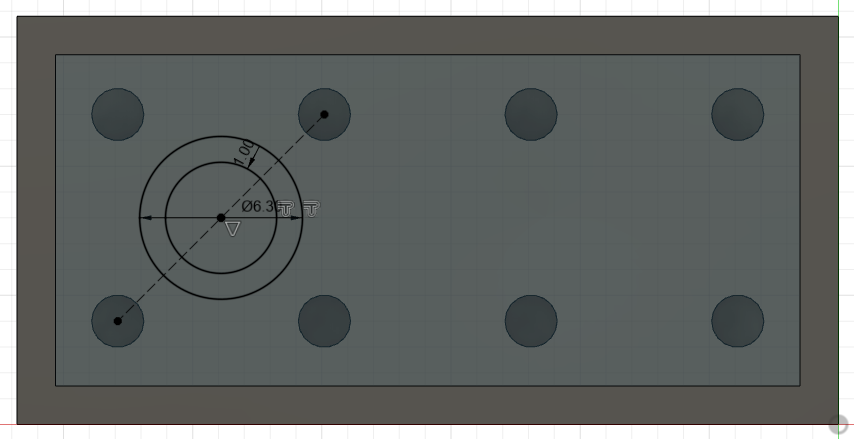
The result of setting the offset shows the final sketch for our initial tube.
To create the initial tube, we will go to Solid > Extrude and set it to the distance we want it to extend. Note that this value should not be more than the height of the block itself.
Note
Notice that the operation here also says Join which means that our tube will be joined with our block as one 3D body as well.

The initial tube after being extruded is complete. We can now use it to create the other two tubes.
By following the same steps as we did with duplicating the studs, we will use the Rectangular Pattern tool again for the same purpose. Setting the Object Type as Features again since our tube is connected to one body. We choose the Axes to the boundaries of the block. Also referencing the photo, we set the quantity to 3 lengthwise.
Tip
In Fusion 360, the arrows that appear while using the Rectangular Pattern tool can be dragged along the axes that you set and can preview the shapes that will be duplicated. These are not visible in screenshots but are helpful for checking if the pattern you are setting is correct or not before hitting OK.
The result after shows the completed row of tubes on the bottom of the toy block.
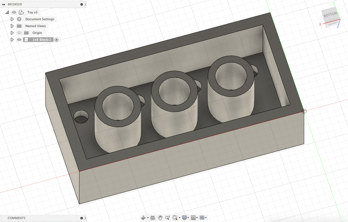
From this view, we can see all features of the toy block are complete.
Step 4: Polishing the Design of the Toy Block
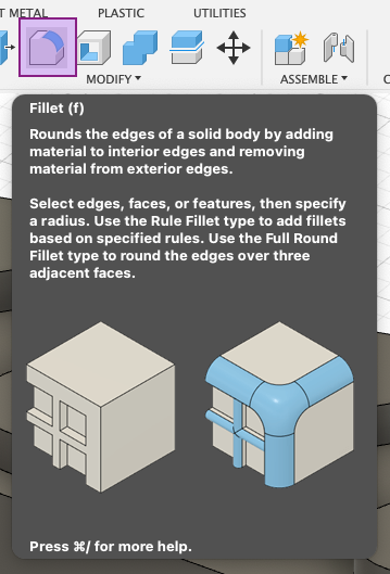
There are many ways to polish a design. We can first start by softening the hard edges of the block by using the Fillet tool.
We can select all the edges of the studs and the block and set the value we want for the fillet.
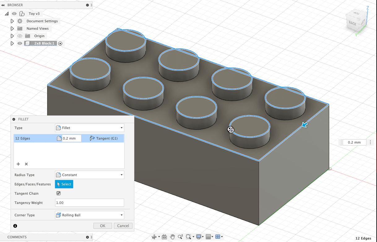
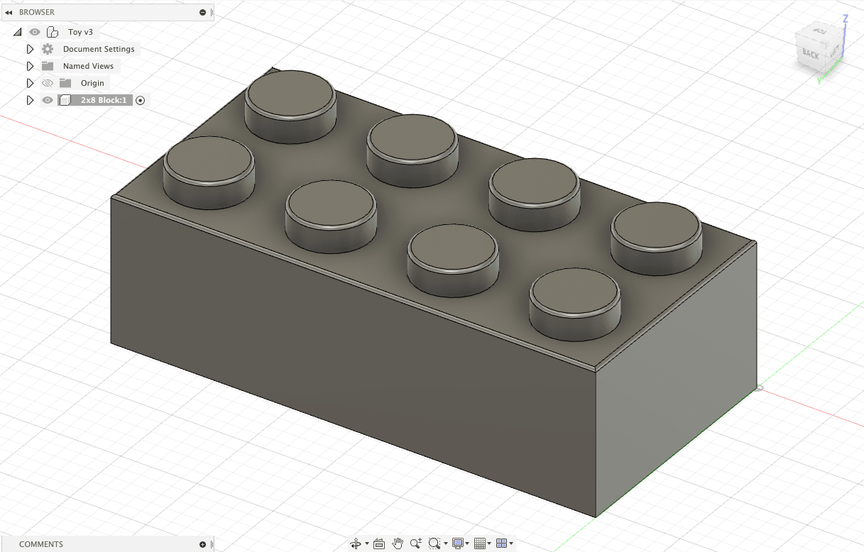
Just that slight change made it look more polished.
Next, we can change the color of the design. This had no impact on the actual fabrication of the design since that depends on the raw material used, but it will give an idea digitally of what the product would look like once fabricated.
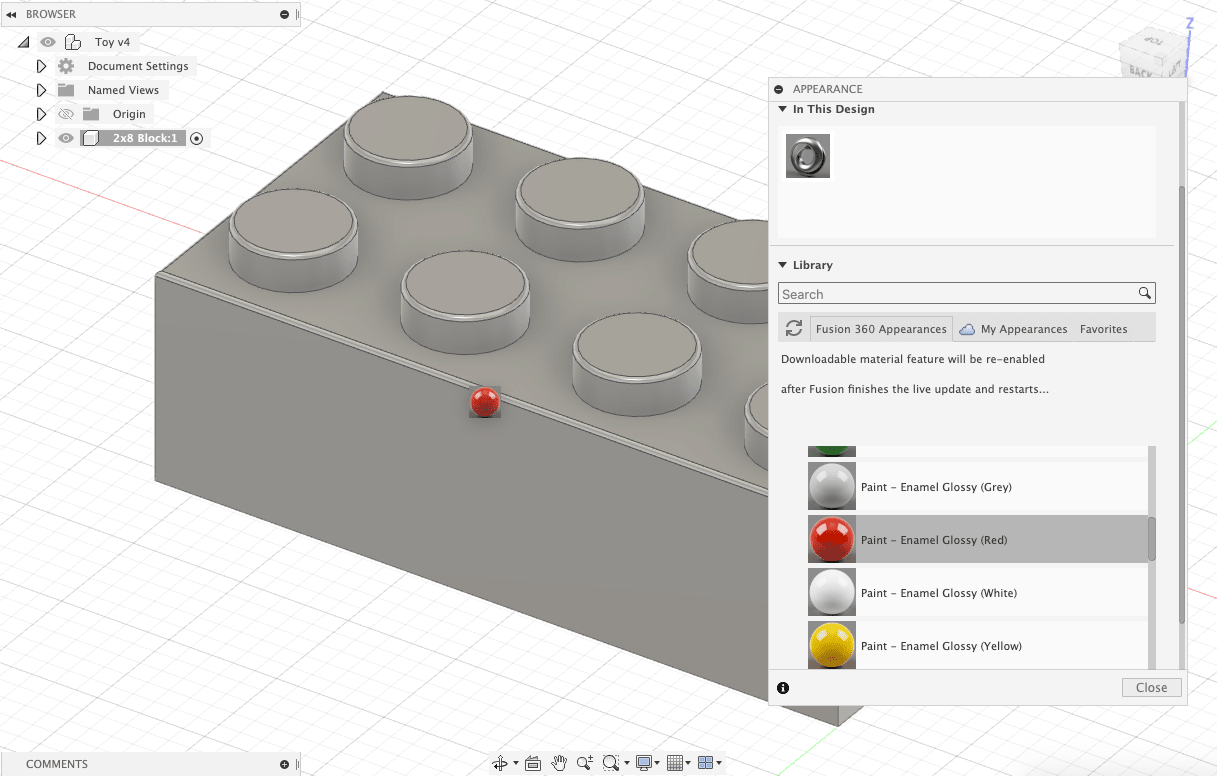
We can do this by going to Modify > Appearance.
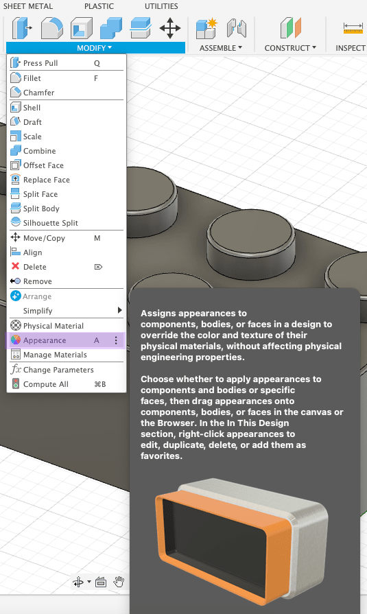
To get the finish of a plastic toy block, I chose Paint > Glossy.
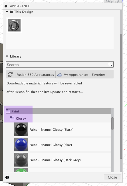
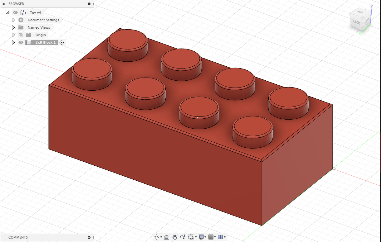
To use the color, simply hold and drag the color onto the model.
The final result of the toy block.
Step 5: Exporting and Sharing the Design
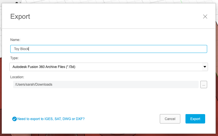
We can export our 3D models multiple ways on Fusion 360. The first is as a F3D file, which will be editable on the application software. Also good for saving the files locally since it saves all projects on the cloud.
You can download mine here to open up on Fusion 360!
Another way to export 3D models is as a STL file, which we can then upload to Sketchfab to share or embed.
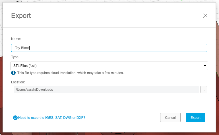
Aftering signing up on Sketchfab and clicking Upload, we can then publish our model.
Note
Set the download as Free so it can be downloadable.
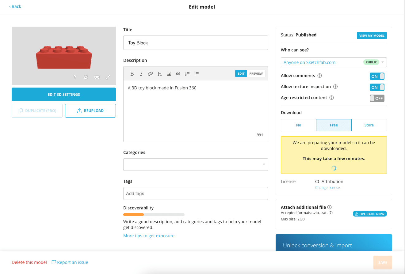
Visiting the page that you published, you can then click on Embed and copy to your clipboard the embed code.
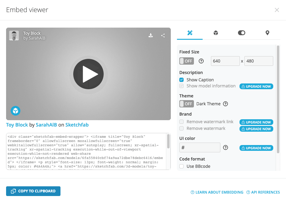
Here is an example of embedding my toy block design on Sketchfab:
The final way to share our design is by generating a share link directly from Fusion 360 that we can then embed directly and make it available for download.
We can do this by right-clicking on our project file, and going to Share Link. This will then show a window where we can generate a link and choose for it to be downloadable.
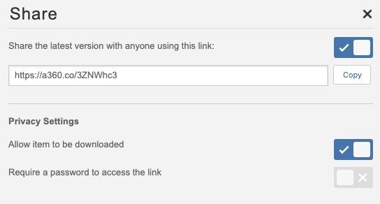
The code for embedding the share link is as follows, while inserting your share link into src="INSERT LINK":
<div class="fusion"><iframe width="640" height="480" src="INSERT LINK" frameborder="0" allow="autoplay; fullscreen; vr" mozallowfullscreen="true" webkitallowfullscreen="true"></iframe></div>
Here is the result of embedding our share link:
Tip
Note that these will not display on Atom, so to check out the design you included, push it to your website and double-check that it is interactive and downloadable!
Blender: a Free Open-Source 3D Modelling Software
Features of Blender
- Multiple workspaces for modeling, sculpting, rendering, animation, etc.
- Used by professional designers and artists of multiple fields, including movie animation, video game development, VFX artists, and character designers to name a few.
- Bug fixes are handled quickly since it’s an open-source software (and a great free alternative!)
Blender can be a difficult and overwhelming software to use for beginners, as it has so many useful features to offer, and also requires a good knowledge of how to navigate around the application.
During my research, I found a great resource through a creator that exclusively makes Blender tutorials, I will be following one to create a doughnut  for this design!
Tip
He also provided the following Blender Shortcut Hotkey Cheatsheet that was handy during the design process.
My Design on Blender
Step 1: Creating the Doughnut
Tip
The controls for panning, orbiting and zooming in and out on the canvas are as follows:
Orbit = Hold scroll-wheel and move mouse
Pan = SHIFT + scroll-wheel and move mouse
Zoom in/out = move scroll-wheel up and down
You can also use some commands, such as Grab for moving objects around and Scale for scaling up or down objects, according to a specific axis, as follows:
Grab = G + move mouse
Grab along X/Y/Z = G + SHIFT + X/Y/Z + move mouse
Scale = S + move mouse
Scale along X/Y/Z = S + SHIFT + X/Y/Z + move mouse
To begin, I delete the cube that automatically opens in a new project. You can do this by left-clicking to select the cube and clicking the hotkey X.
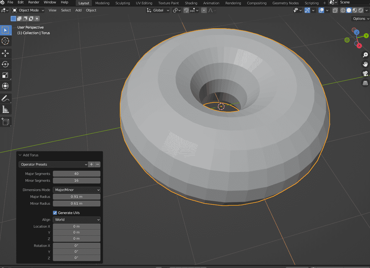
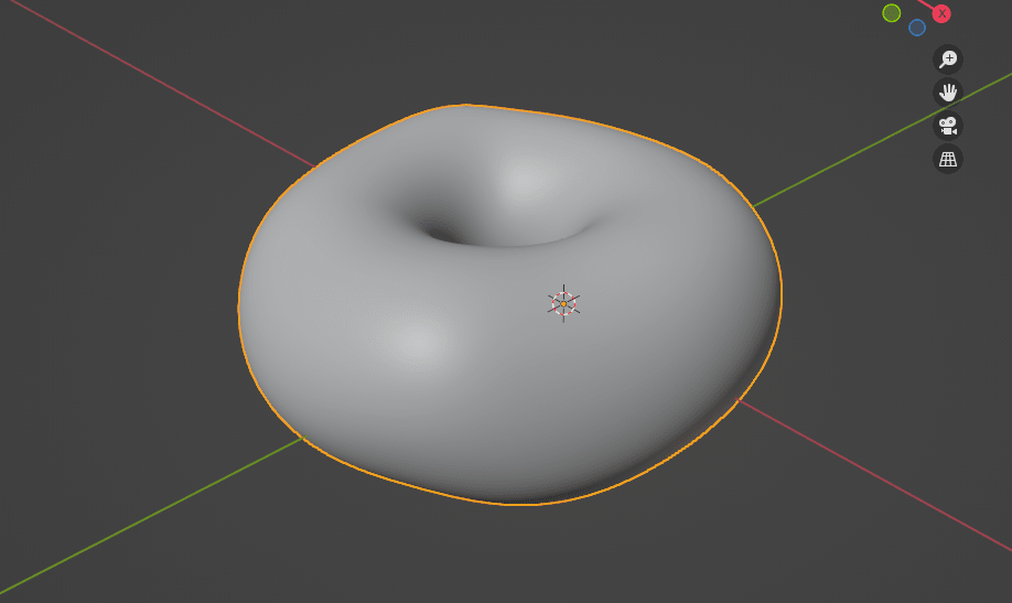
I then added a shape that would most closely resemble a doughnut, which is a Torus shape. To add it, click SHIFT + A and navigate the pop-up menu to Mesh > Torus.
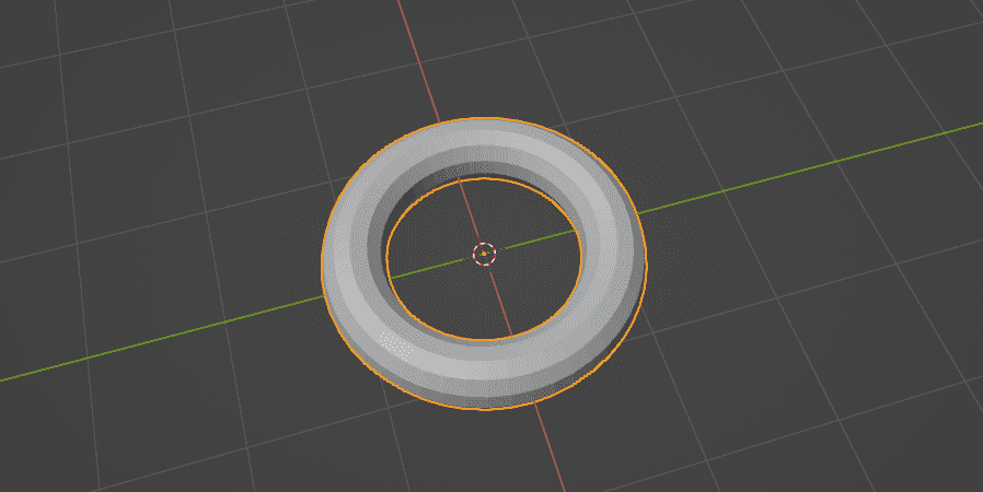
To adjust the faces on the shape, I changed the Major and Minor Segments shown on the Add Torus menu that pops up after adding the shape. It is important to keep the base design as low-poly as possible, as we can smooth it out later on in the design process, and a high-poly base model will make this unnecessarily difficult to render at the end.
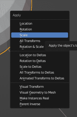
I then re-scaled the shape to 9 cm by clicking S, then CTRL + A to open up the Apply menu and clicking Scale to apply the change.
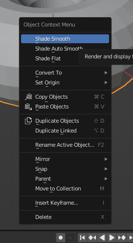
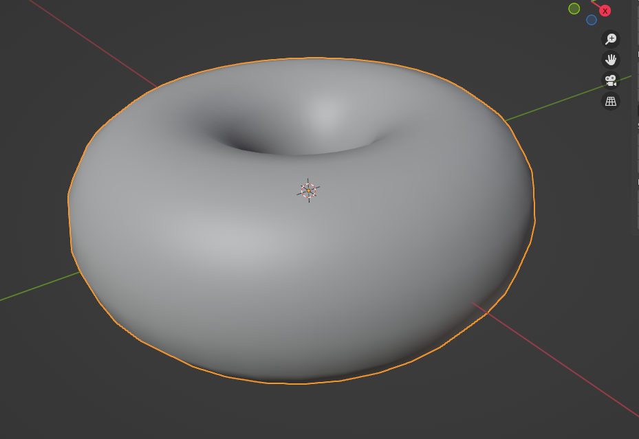
I then select the shape and click on !!!!!!!!!! and Shade Smooth to round out the faces to look more like a doughnut.
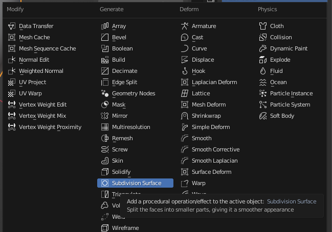
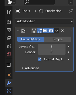
To start editing, I start by clicking on the drop-down menu on the top toolbar where it says Object Mode and selecting Edit Mode. I then navigate to the wrench  icon on the toolbar on the right side and click Add Modifier > Subdivision Surface. This will allow me to to split the faces of the torus mesh into smaller faces to give it a smooth appearance and also so I can add more detail to it in the design process.
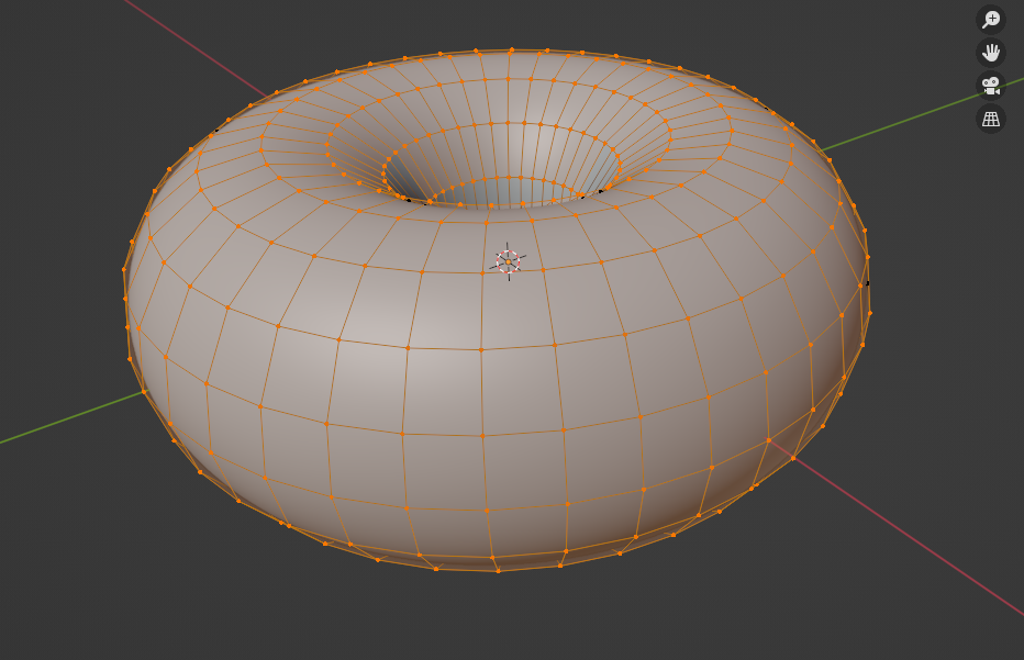
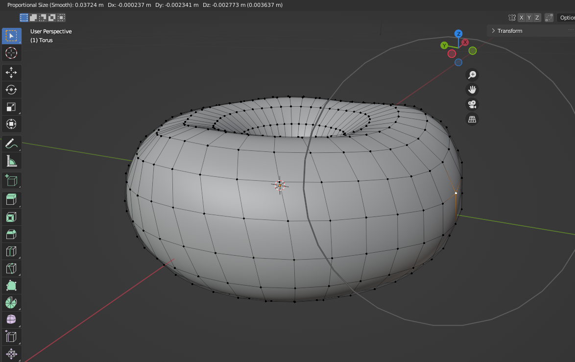
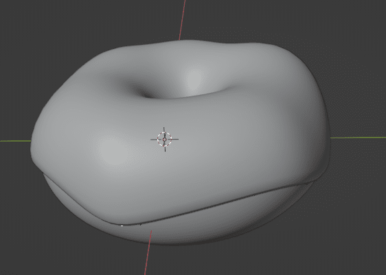
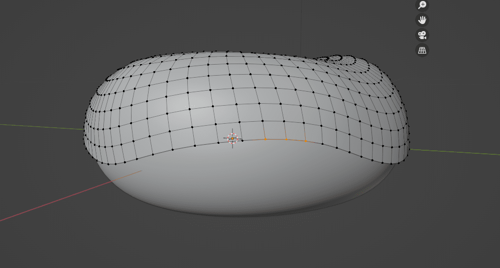
After applying it, we can now see the vertices manipulate the shape to make it more irregular and organic. To do this, I first click on O to turn on Proportional Editing, then click on a point on the side I want to add shape to and use Grab by clicking G to manipulate the shape of it to make it wider on different sides of the doughnut. The benefit of using Proportional Editing for this part is that it will pull multiple points together at once, making the shape manipulation process faster and look much smoother than if I manually selected each face or vertix that I wanted to change.
Now our doughnut isn’t a perfect torus shape and looks more organic (switch back to Object Mode to see how it looks so far):
Tip
It helps to look at reference images of whatever you’re modelling! I looked up photos of doughnuts with icing on them on Google Images for this design.
Step 2: Creating the Icing on the Doughnut
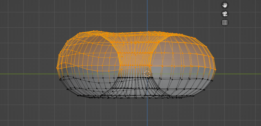
For the next part, I want to add the icing that will lay on top of the doughnut. To do this, I will first align to the side view of the doughnut by clicking the NUMPAD 3 on my keyboard.
Note
Numpad shortcuts only work on the actual numpad on a keyboard, not the row of numbers on the top half of the keyboard. If you don’t have this on your laptop keyboard, you can instead click the axis you want to rotate your view to on the top right-hand corner of the canvas.
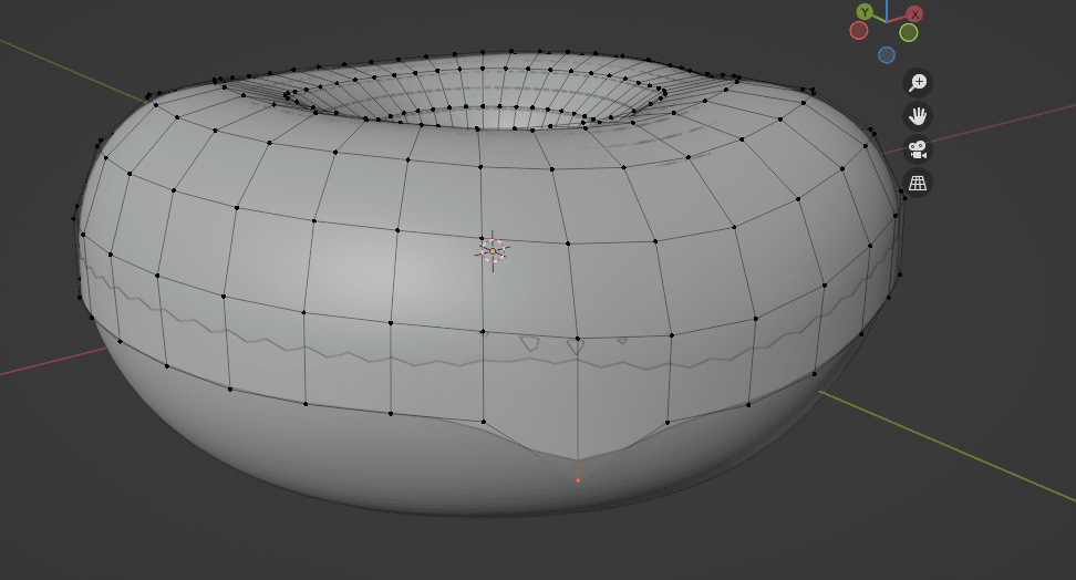
I will then click Z and select Wireframe to allow me to select the whole top half of the doughnut, then click SHIFT + D to duplicate the selected area.
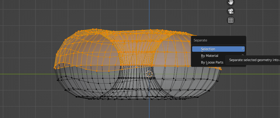
To make the duplicated top half a separate component than the doughnut itself, I click on P to open up the Separate menu and click on Selection.
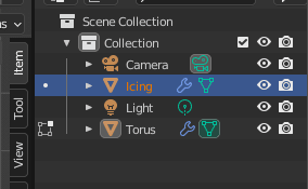
This will create a new object called Torus.001, which will be added to our Collection that we can see on the top of the right toolbar. We can rename this to Icing and rename Torus to Doughnut for clarity.
Note
We can also see Light and Camera in our Collection. We’ll use these later when we get to the rendering part of the design.
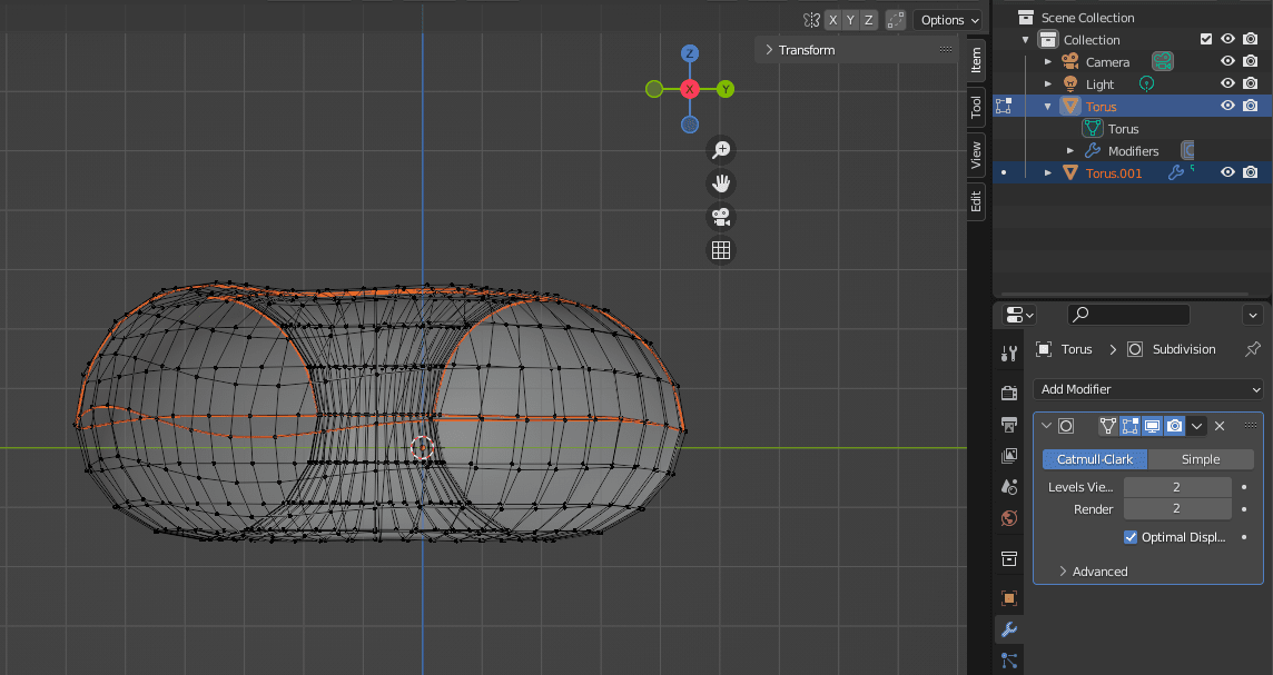
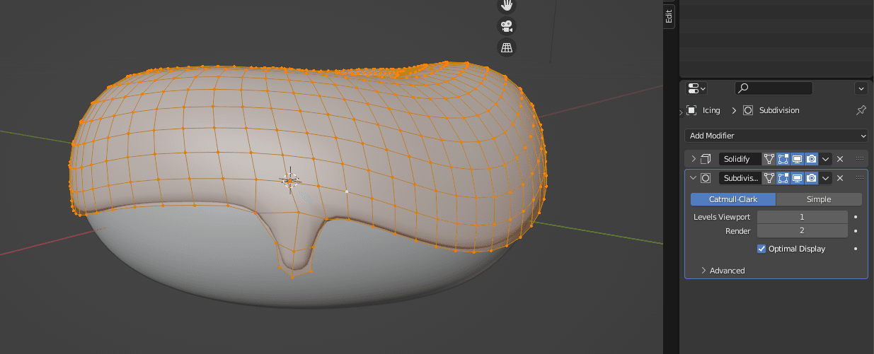
Now, to start editing the icing on the doughnut, I switch to Edit Mode, then go to Add Modifier > Solidify, which adds depth and thickness to our mesh.
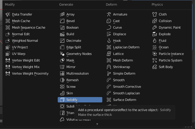
We use Solidify because we want it to be a thicker layer sitting on top of the doughnut and we’ll be able to see the icing separate from the doughnut more easily. It also smooths it out so it looks better!
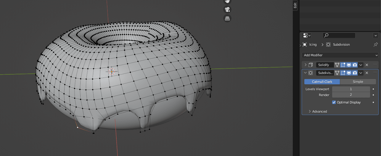
We first need to adjust the Solidify settings for it to look right. We change the Offset to 1 and Thickness to 0.03 m. We’ll also be moving the Solidify modifier to be above the Subdivision Surface modifier by clicking on the dots on the right side of them and dragging up. The arrangement of modifiers matters, since each change is applied in order, and we want to make the icing mesh thicker before we divide it into smaller faces to edit it.
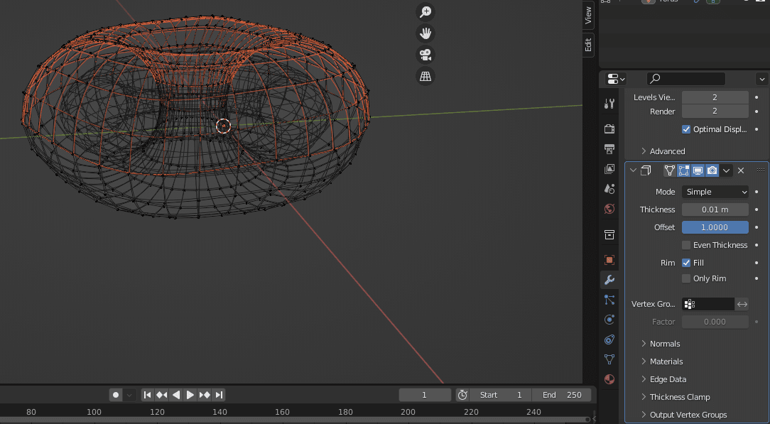
This is how it looks like so far, where we can see the icing is draped over the doughnut:
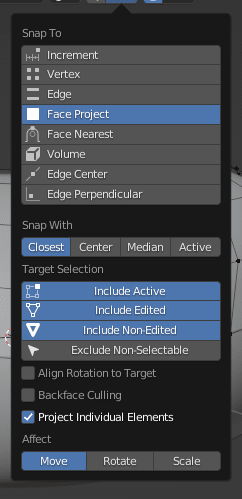
Now, before editing, we will change the Snap To settings on the top toolbar above the canvas and changing it to Snap to Face Project and checking the box to turn on Project Individual Elements. This will allow any edits we make to the Icing object to snap to the face of the Doughnut object underneath it.
Next, we can hide the shape of the icing that we got from Solidify to see the vertices underneath to start editing by clicking on the second icon to toggle Hide/Unhide.
(icon on modifier list)
Now with access to the vertices and with Proportional Editing still on, we will repeat the same procedure by using Grab by clicking G to manipulate the shape of the icing.
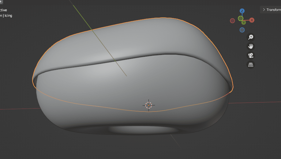
We can also toggle the same icon from before to show the changes that we’re making to the icing.

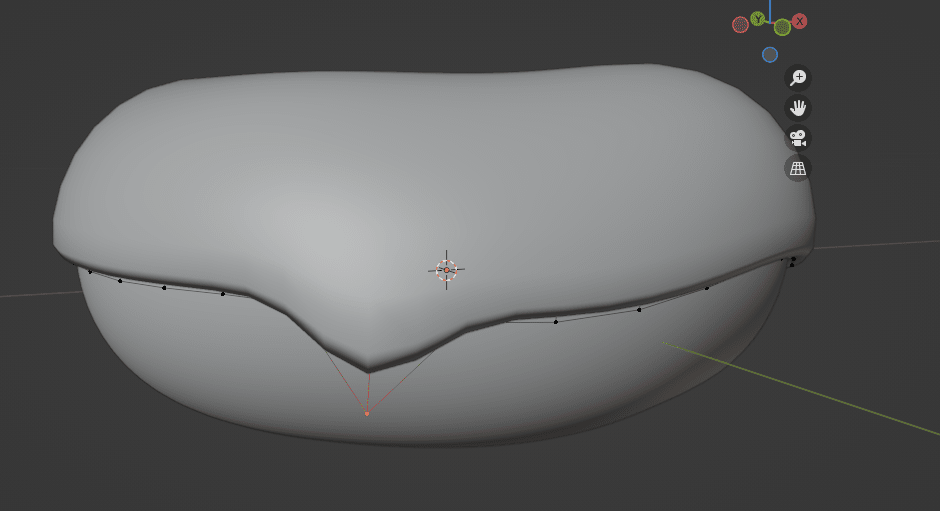
After some editing, this is what the icing looks like so far. It’s starting to come together and look more like a doughnut!
Next, I’d like to add more detail in the icing by making dripping pieces. To do this, I’ll select the bottom edge of a couple of vertix points and click on E to Extrude. This will create new faces that are part of the icing. We can click and move around points with G or we can make them smaller or bigger with S.
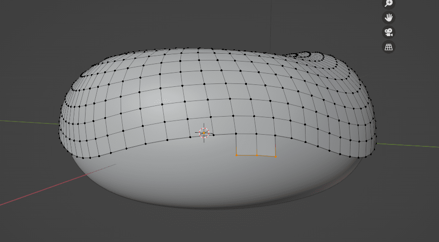
We can now see it looks like a drippy piece of icing!
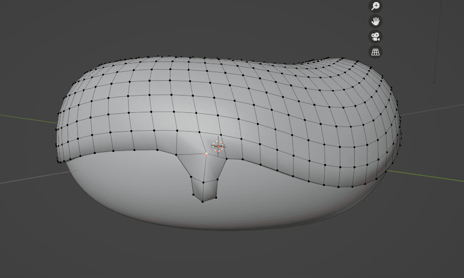
I then repeat this process on the rest of the edges of the icing until I’m satisfied.
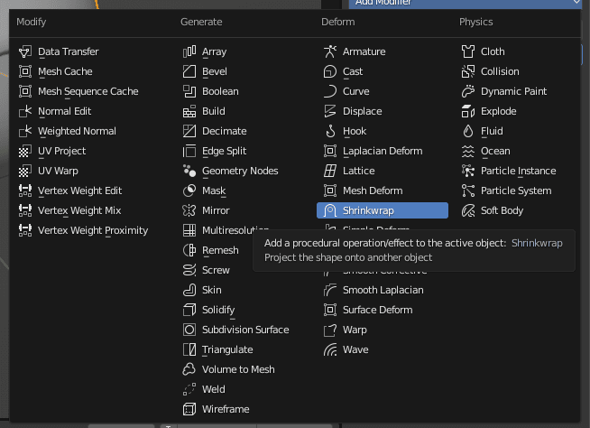
Notice that not all the drops fall correctly onto the doughnut underneath and look like they’re sticking out. We’ll fix this by adding the Shrinkwrap modifier and dragging it to the top of the modifier list, then increasing the Offset to 0.002 m. We can now see that it lays on top of the doughnut better.
We’re now done modelling our icing doughnut for now! Before we move on, we must apply the modifiers to our model by clicking the  arrow and clicking Apply to each modifier. It’s important to do this in the order that we listed them: Shrinkwrap, Solidify, then Subdivision Surface.
Step 3: Sculpting the Icing Doughnut
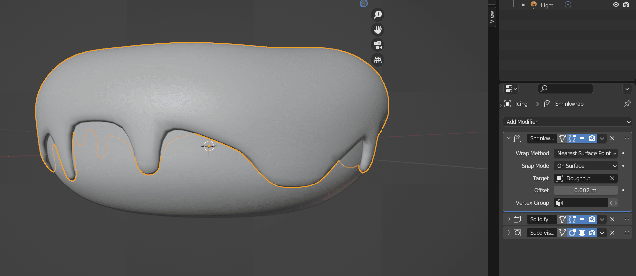
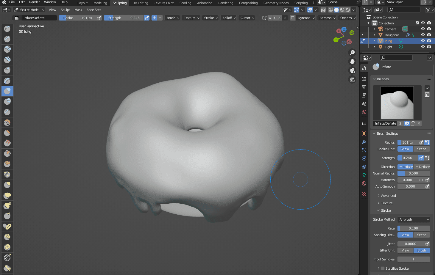
To enter the Sculpting mode on Blender, I clicked on the Sculpting tab in the top toolbar. Which will open a different workspace that is filled with brushes.
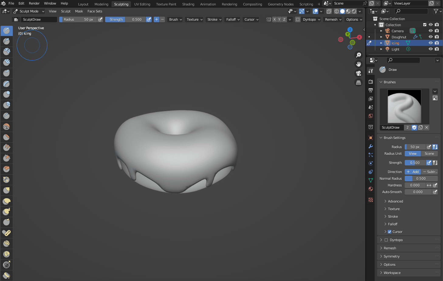
You need to use every brush to get the desired effect you want. For sculpting my design, I primarily used the Draw brush (you can add texture by clicking dragging on the surface you want to have rise, and to remove texture you can hold SHIFT while clicking and dragging to have the surface recede).
Other brushes I used were the Smooth brush, which takes away texture in case you overused the texturising brushes and made a mess. Another is the Inflate brush, which I used to inflate and make the ends of the icing droplets look rounder.
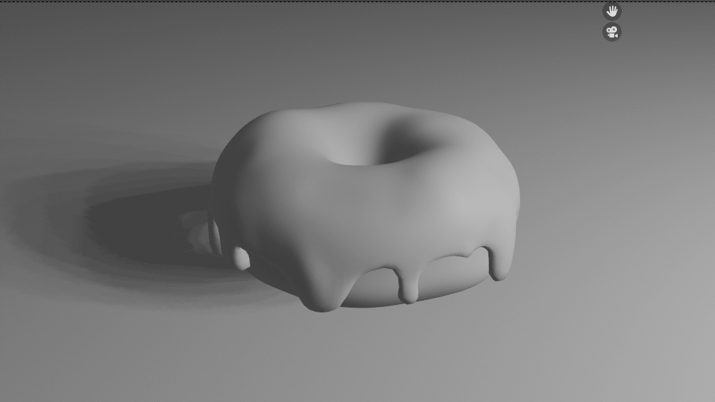
After randomly using the brushes until I was satisfied, the doughnut ended up looking like this!
Step 4: Rendering the Icing Doughnut
To start rendering, we first must adjust the camera and light source to both show and accent our doughnut model. We need to make sure the camera is in frame, and also move around the light source until it is both lighting and casting a shadow against the doughnut well enough to like aesthetically pleasing and accentuate the texturising we did during sculpting.
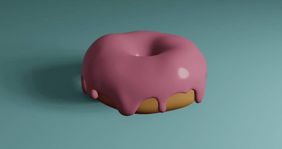
Next, I added colour to the icing, doughnut and create a plane mesh to sit under the doughnut to act as a background for a pop of colour.
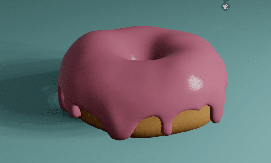
This is the final result after rendering:
Step 5: Exporting the Design as STL
If I wanted to 3D print my design, I’d have to save it as an STL file. Another benefit of this file format is that I can also open it up on Fusion 360 and edit it from there if I would like to.
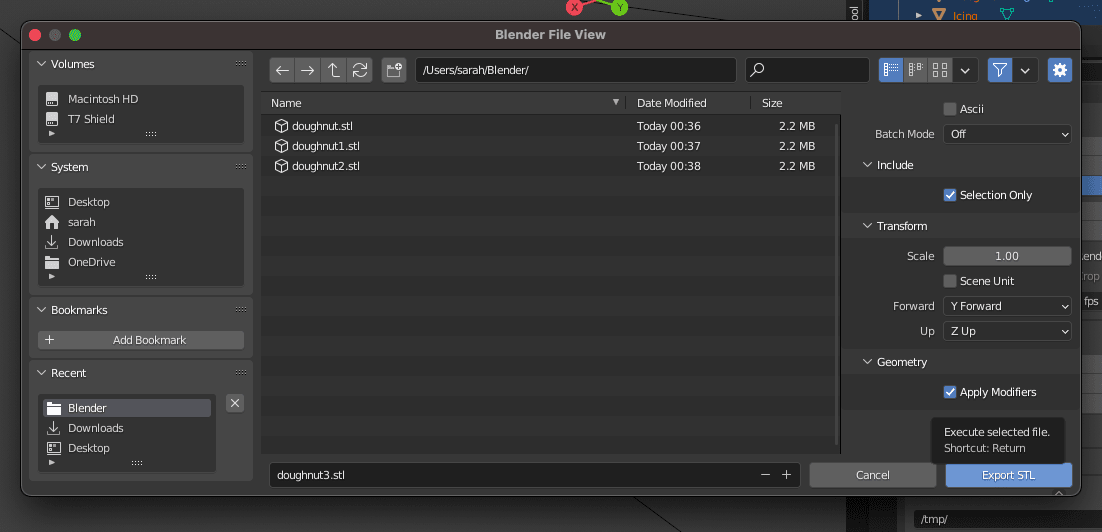
To export the design in the correct format, navigate to File > Export > Stl (.stl):
Here is my Blender file imported into Fusion 360:
Here it is on Sketchfab: