Week 8: Inputs and Outputs
This week we learned how to use input and output devices to program them to combine their functions for a desired end result.
For this week, we had to use one input and one output. The input would be used to control the function of the output.
From my understanding of the Adafruit Feather nRF52840 Express that I gained from the assignments of Week 6, I knew that it was equipped with an on-board NeoPixel RGB LED. I knew I wanted to use this exact type of LED for my final project, so I decided I’d learn everything about programming and controlling it during this week’s assignment!
For my output, I decided that it would be a waste to use something simple like a switch to cycle between static colours. With that, I decided the perfect idea was to use a joystick module to cycle between the entire colour spectrum, since RGB LEDs can display combinations of colours, depending on each of the Red, Green and Blue values.
Step 1: Controlling the on-board NeoPixel RGB LED
For this part, I knew all I needed to do was light up the LED. However, since it was an RGB LED, I wanted to see it light up in all of the colours of the rainbow and more.
I learned from reading the Adafruit Feather nRF52840 Express documentation that it had a on-board NeoPixel RGB LED.
![]()
To make it work, I followed this tutorial on the Adafruit learn website.
This was the code that I used:
Note
The reason for the DotStar condition in the code is because different boards have different ob-board RGB LEDs. I already knew from reading the Adafruit Feather nRF52840 Express documentation that it had a NeoPixel, but kept the condition to avoid possible errors.
import time
import board
from rainbowio import colorwheel

if hasattr(board, "APA102_SCK"):
    import adafruit_dotstar

    led = adafruit_dotstar.DotStar(board.APA102_SCK, board.APA102_MOSI, 1)
else:
    import neopixel

    led = neopixel.NeoPixel(board.NEOPIXEL, 1)

led.brightness = 0.3

i = 0
while True:
    i = (i + 1) % 256  # run from 0 to 255
    led.fill(colorwheel(i))
    time.sleep(0.01)
You can download the code here
This code will automatically cycle through the colour spectrum at a certain delay time in between cycles. This is what it looked like:
Step 2: Controlling the Joystick Module
For the part, I needed to control the joystick, but I needed to be able to see it output something to know that it works.
A bit about the joystick module
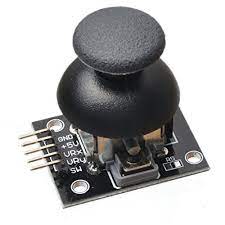
There are a few different pins on this module, here they are:
| Pin Name | Description |
|---|---|
| GND | Ground terminal |
| +5V | Positive power supply terminal |
| VRx | Variable voltage potentiometer for the X-axis (Analog) |
| VRy | Variable voltage potentiometer for the Y-axis (Analog) |
| SW | Switch (Digital) |
Note
Knowing the names of pins and their purposes for each module help you understand why we make certain connections to the microcontroller for them. For example, some of the pins I labelled as either Analog or Digital. This is because of the way the output data is being processed for each of them.
The potentiometer values are analog because their output data varies, and is never a whole number (or an integer). Therefore, we know to connect the VRx and VRy pins to the analog pins of our microcontroller.
On the other hand, the switch can only output data the value of either 0 or 1 (a.k.a., True or False). Since the output data is a simple integer, we know we can connect the SW pin to a digital pin on our microcontroller.
The joystick module functions by varying the resistance of the potentiometers whenever the joystick is moved, which gives us different output data to determine the position of the joystick on the axes.
Info
You can read more about the joystick module here.
To do this, I followed this tutorial that would control my laptop’s mouse with the joystick.
This is how the connections were made:
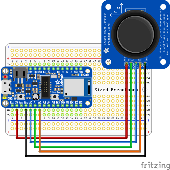
You can download the file to open in Fritzing here
Info
To illustrate the connections, I downloaded and used Fritzing, as well as the Adafruit Library made for Fritzing, which I imported and used by following this tutorial.
This was the code that I used:
import time
import analogio
import board
import digitalio
import usb_hid
from adafruit_hid.mouse import Mouse

mouse = Mouse(usb_hid.devices)

y_axis = analogio.AnalogIn(board.A0)
x_axis = analogio.AnalogIn(board.A1)
select = digitalio.DigitalInOut(board.A2)
select.direction = digitalio.Direction.INPUT
select.pull = digitalio.Pull.UP

pot_min = 0.00
pot_max = 3.29
step = (pot_max - pot_min) / 20.0


def get_voltage(pin):
    return (pin.value * 3.3) / 65536

def steps(axis):
    """ Maps the potentiometer voltage range to 0-20 """
    return round((axis - pot_min) / step)


while True:
    x = get_voltage(x_axis)
    y = get_voltage(y_axis)

    if select.value is False:
        mouse.click(Mouse.LEFT_BUTTON)
        time.sleep(0.2)  # Debounce delay

    if steps(x) > 11.0:
        # print(steps(x))
        mouse.move(x=1)
    if steps(x) < 9.0:
        # print(steps(x))
        mouse.move(x=-1)

    if steps(x) > 19.0:
        # print(steps(x))
        mouse.move(x=8)
    if steps(x) < 1.0:
        # print(steps(x))
        mouse.move(x=-8)

    if steps(y) > 11.0:
        # print(steps(y))
        mouse.move(y=-1)
    if steps(y) < 9.0:
        # print(steps(y))
        mouse.move(y=1)

    if steps(y) > 19.0:
        # print(steps(y))
        mouse.move(y=-8)
    if steps(y) < 1.0:
        # print(steps(y))
        mouse.move(y=8)
You can download the code here
Info
Notice that I did not use a digital pin for the SW pin, and instead connected it to an analog pin and translated the data into digital values in the code.
You can do either, depending on your needs. This can be useful to know if you don’t have any available digital pins, for example.
This code will translate the potentiometer readings of the joystick into positional changes for the laptop’s mouse. Here is a screen recording of it doing just that:
You can see clearly that the movement isn’t as fluid it would be if I was using my trackpad. I switch between positioning the joystick all the way North, South, East and West, then just move it in circles to show that it’s working. Clicking the joystick would left-click the mouse. Here is the video of me moving the joystick that corresponds with the screen-recording video:
Step 3: Combining it into a Joystick-Controlled NeoPixel RGB LED
Finally, I am ready to combine the functions of each of these, with the joystick module as an input controlled the on-board NeoPixel RGB LED as an output.
Note
I used the same connection as the previous step since the LED does not require any connections.
Here is the code I used for this:
import time
import analogio
import board
import digitalio
from rainbowio import colorwheel

if hasattr(board, "APA102_SCK"):
    import adafruit_dotstar

    led = adafruit_dotstar.DotStar(board.APA102_SCK, board.APA102_MOSI, 1)
else:
    import neopixel

    led = neopixel.NeoPixel(board.NEOPIXEL, 1)

led.brightness = 0.3
i = 0
y_axis = analogio.AnalogIn(board.A0)
x_axis = analogio.AnalogIn(board.A1)
select = digitalio.DigitalInOut(board.A2)
select.direction = digitalio.Direction.INPUT
select.pull = digitalio.Pull.UP

# potentiometer of joystick
pot_min = 0.00
pot_max = 3.29
step = (pot_max - pot_min) / 255.0  # 255 for colorwheel

def get_voltage(pin):
    return (pin.value * 3.3) / 65536

def steps(axis):
    """ Maps the potentiometer voltage range to 0-255 """
    return round((axis - pot_min) / step)

while True:
    x = get_voltage(x_axis)
    y = get_voltage(y_axis)

    if select.value is False:
        led[0] = (255, 255, 255)  # white if click
        time.sleep(0.5)

    if steps(x) < 2.0:
        i = (i + 1) % 2
        led.fill(colorwheel(i))

    if steps(x) < 4.0:
        i = (i + 1) % 4
        led.fill(colorwheel(i))

    if steps(x) < 8.0:
        i = (i + 1) % 8
        led.fill(colorwheel(i))

    if steps(x) < 16.0:
        i = (i + 1) % 16
        led.fill(colorwheel(i))

    if steps(x) < 32.0:
        i = (i + 1) % 32
        led.fill(colorwheel(i))

    if steps(x) < 64.0:
        i = (i + 1) % 8
        led.fill(colorwheel(i))

    if steps(x) < 128.0:
        i = (i + 1) % 128
        led.fill(colorwheel(i))

    if steps(x) < 256.0:
        i = (i + 1) % 256
        led.fill(colorwheel(i))
You can download the code here
This code will translate the potentiometer readings of the joystick into colour changes. Each points in the axis are assigned with different RGB values of true Red, Green and Blue, with the neutral position as white. When moving the joystick in circles, we can see that the LED cycles through the colour spectrum as the RGB values transition. Clicking the joystick would change it to white.
Here is a video of it doing just that where you can see the joystick and the on-board NeoPixel RGB LED: