Week 7: Moulding and Casting
This week we learned how to make moulds out of our 3D designs, mill them out, and then cast them to create a finished product.
Limitations for Milling Out Moulds
As we learned during Week 5: Computer-Controlled Machining, the milling process is done to create 2D cuts onto your material. Not too far from 2D laser cutting, but the difference is that we can guide the milling to make specific cuts to replicate 2.5D, which isn’t exactly 3D, but can replicate a 3D shape in 2D.
However, in order for us to achieve this, we need to under the limitations of the machines we are working with. First, remember that the milling tip is situated right above the material it is cutting, and is locked in that position the whole time it is cutting out our designs. This means that much of the limitations in what designs we can cut with this type of machining is operating within its reachability. This is further illustrated in the diagram below.
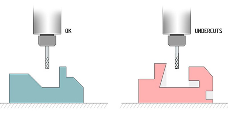
Notice that the diagram on the right shows that the main limitation is not being able to undercut our designs on this machine, this is illustrated in three ways:
Not being able to cut at an inner angle that is greater than the outer angle, as seen on the left angle of the diagram. We can, however, cut inner angles that are larger than 90 degrees, as long as the outer angle is larger than it.
Not being able to make undercuts while keeping material above intact. It also cannot drill from an axis other than the Z-axis (from above). As we saw during Week 4: 3D Scanning and Printing, this is possible with 3D printing with supports, but the drill tip will not be able to go under material to make this cut.
Not being able to cut at an axis other than the Z-axis again. The drill tip will remain in the same position the whole time during the milling process. We can, however, rotate the material and allow it to mill a different side, but there are problems with accuracy as this is subject to human error. Alternatively, there are machines out there that would be able to rotate and accurately position the material to mill different sides of this, while keeping the drill tip fixed at the same position.
We’ll take these limitations into consideration when 3D modelling our designs for the mould.
Group Assignment: Getting Familiar with the Materials
For our group assignment this week, we each experimented with using different types of soft and hard materials to learn what was our best and preferred material to use for our casting later on.
We documented our experiments here, where we learned how to handle and use gypsum for casting.
We learned that we had a short work time if around 5 minutes with this material, but that it had the fastest cure time out of all the materials at 15 minutes.
Once its fully cured, it has a beautiful light grey matte finish, and is super smooth! Which would make it perfect for casts that you want to paint after!
Individual Assignment: Making an Octopus!  
I had the idea to 3D design an octopus for my mould to match my red octopus keychain that I carry around everywhere with me! They’re also my favourite animal, because they’re incredibly intelligent and have an incredibly funny attitude!
Step 1: 3D Modeling the Octopus Mould
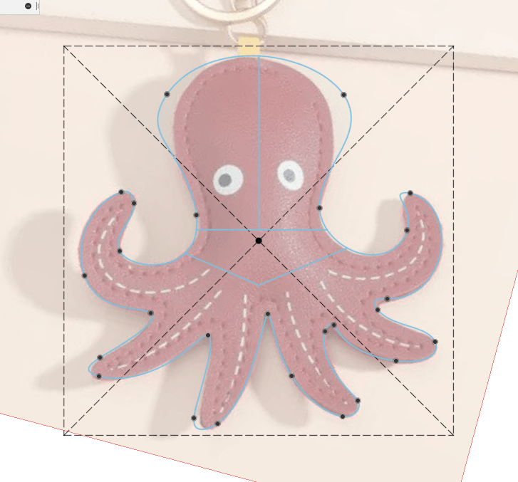
For this step, I used Fusion 360 to make a 3D model of my octopus. I first started out by finding and importing a reference image that has the general shape of what I want to do.

I then started sketching out the octopus using the Fit Point Spline tool to draw curved lines and outline the shape of the reference image.
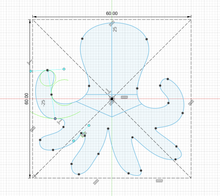
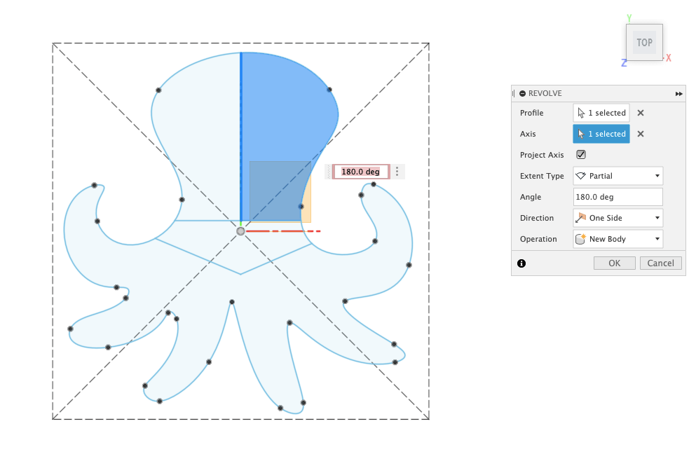
I then selected one half of the head of the octopus and used the Revolve tool to make a perfectly rounded head.
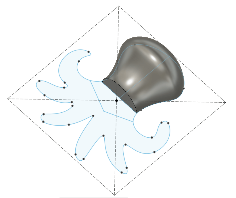
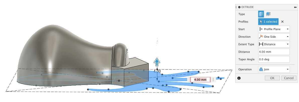
After this, I extruded the collar and the legs!
This is what the final octopus looked like:
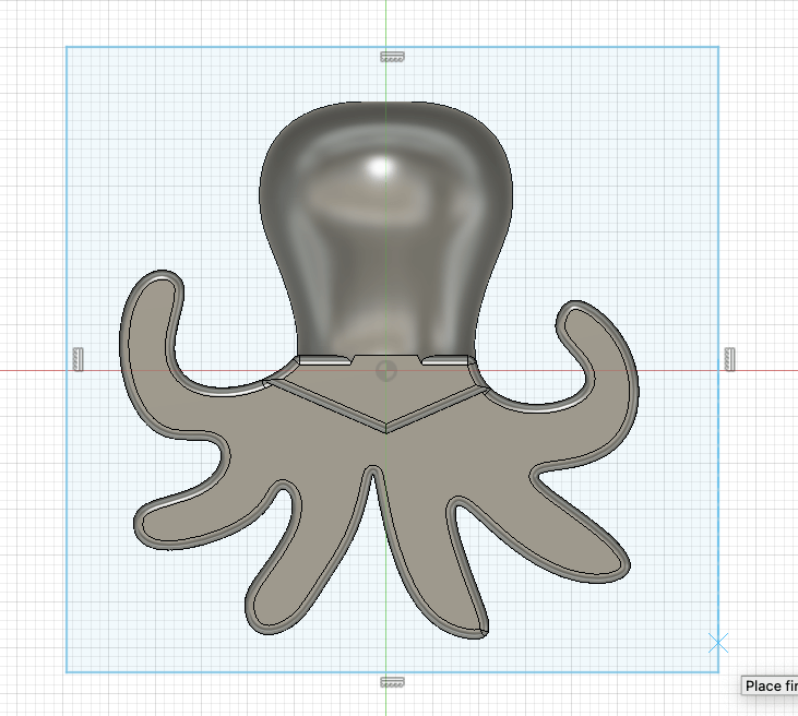
This is the 3D model on Fusion 360:
Step 2: Milling Out the Octopus Mould
We milled out the mould on a hard silicone pad. We started by measuring out the silicone pad because we needed to enter it into the software. This is important for the machine to be able to know what the dimensions of the material it is cutting is, and also for us to correctly line up the moulds both I and my partner want to mill out on one pad.
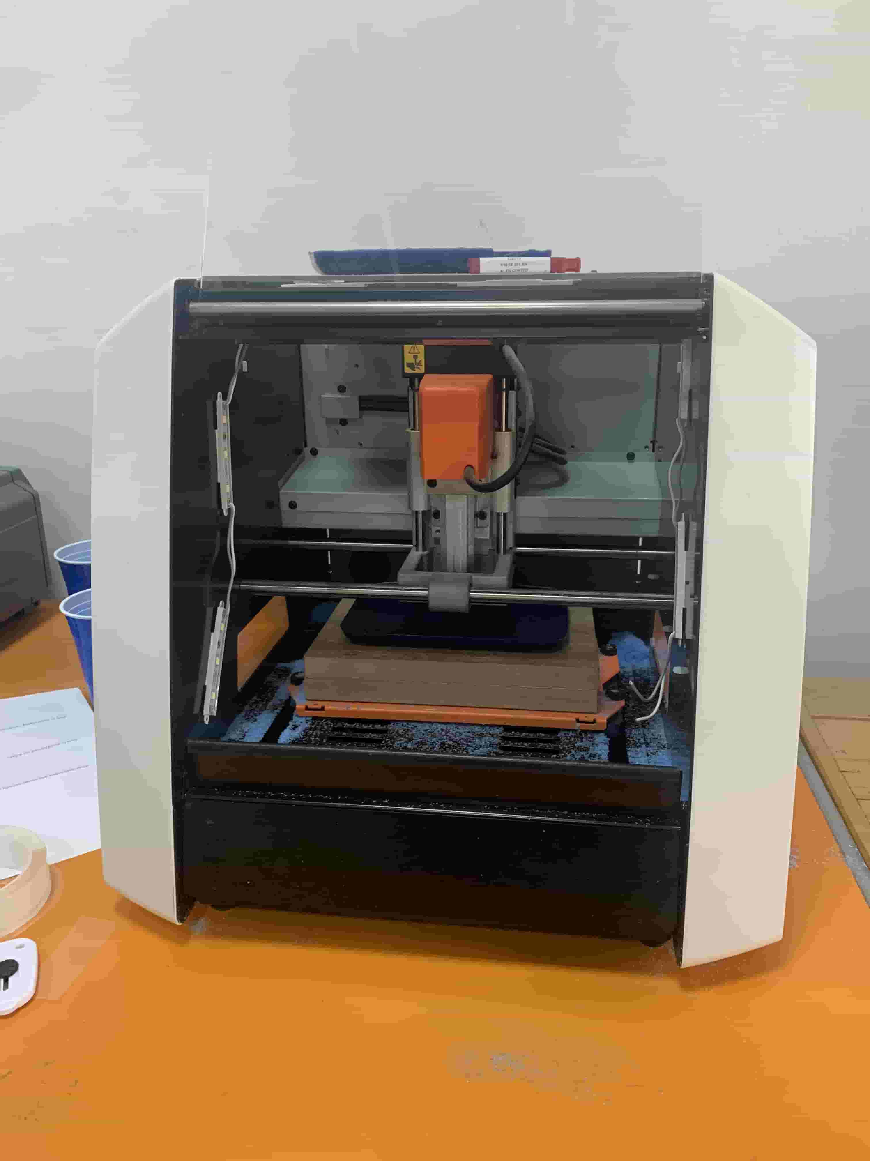
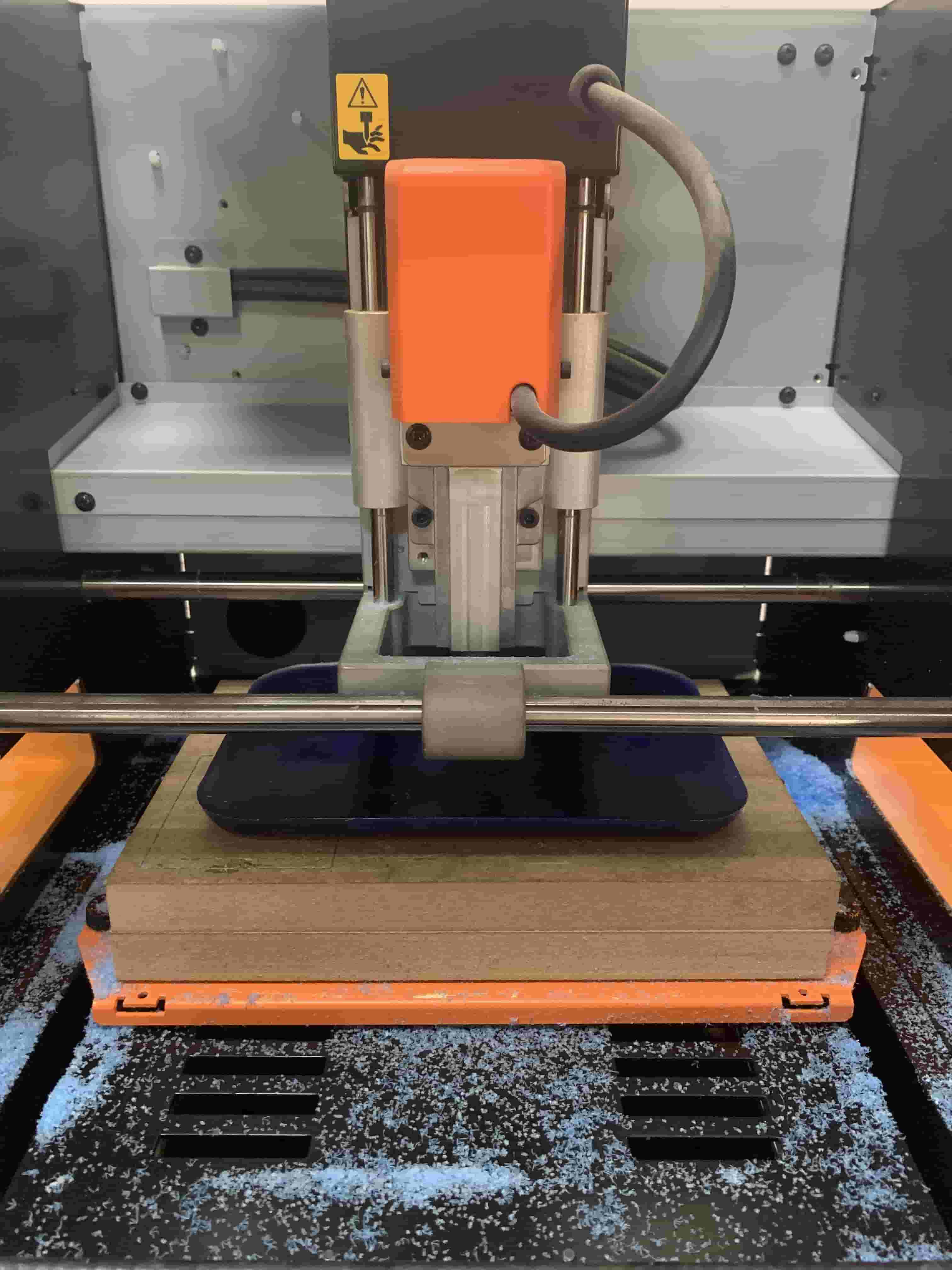
This is the machine we will be using for the milling process. It is basically a smaller scale version of the large-scale CNC machine we worked with during Week 5: Computer-Controlled Machining.
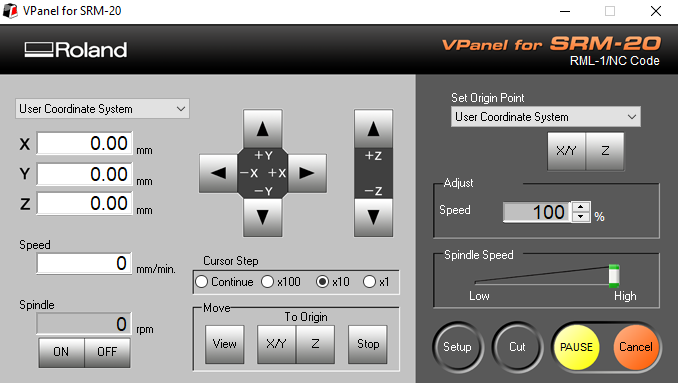
To download our designs for the machine to mill out, we used the SRPPlayer software for editing our file and defining tool paths, then using with VPanel, which is made for the specific milling machine we’re using.
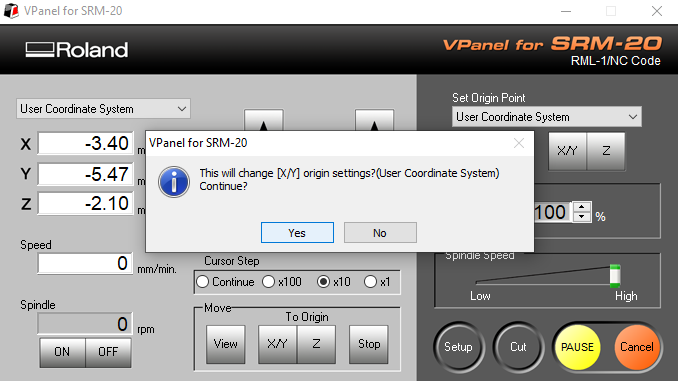
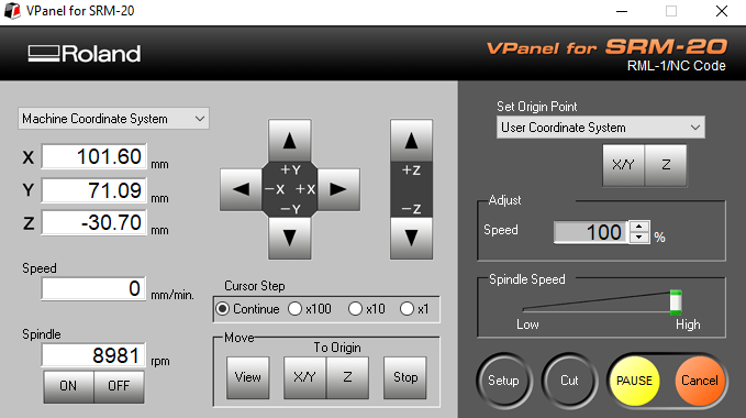
We start by initialising our coordinates to all zeros on the machine, since its already been used before now.
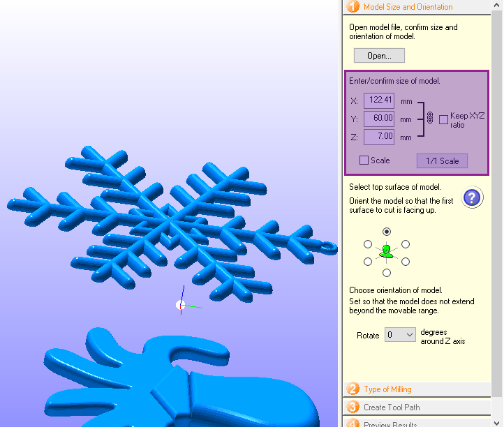
We now start by entering the dimensions for our models that we created. These should be around the same size as the material we will be milling on, but smaller to fit inside.
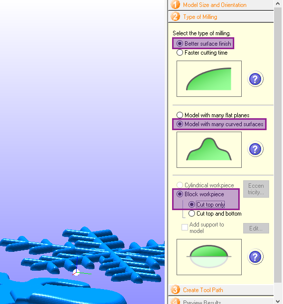
Next, we define some characteristics of the type of milling job we want done. We choose options that might take longer, but will yield the best results, since we will only be milling once and don’t have time to make a prototype/test piece.
We will also choose to only cut the top, since we are creating a mould that we will cast in later. Also because it would be too complex of a task for us to have to manually rotate our material for it to cut other sides of it. Limited it to one direction where we will avoid moving it at all is the best option.
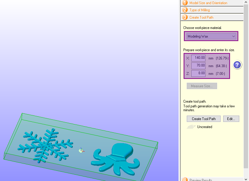
Next, we entered the dimensions fo the material we will be milling that we measured out earlier. This should be larger than the models.
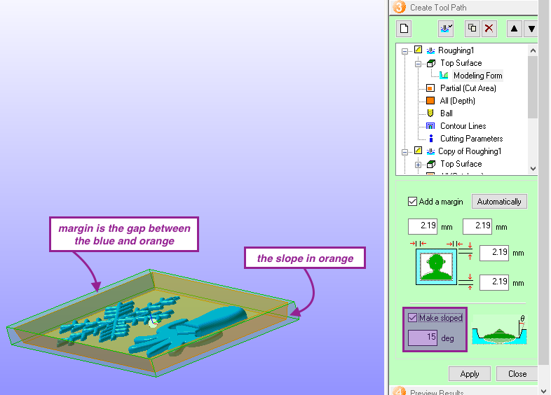
Next, we will create a tool path for it to cut out the overall shape of where the moulds will be. This is also to smooth and even out the surface of the material, which is important to be able to mill accurately to the designs.
We also add a margin and a slope to this overall area that will be evened out.
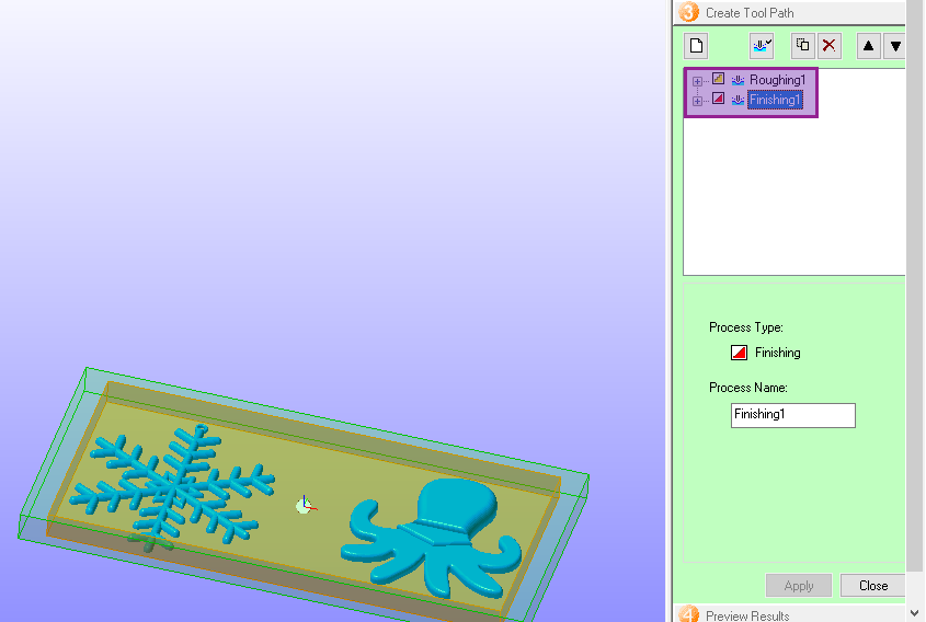
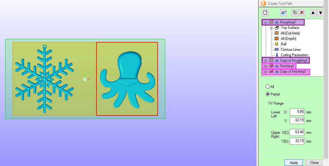
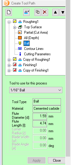
Next, we will create tool paths for each design separately, so that it full finishes cutting out one of them at a time. Notice that we have two copies of both Roughing and Finishing. This is to ensure that the shape is as accurate and as smooth as possible.
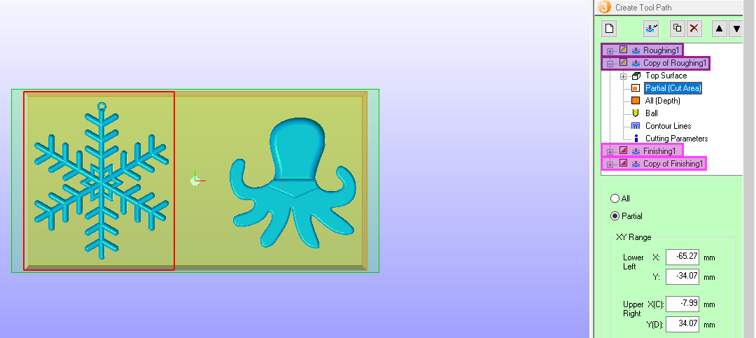
We repeat the same steps with the other model.
We also make sure to select the correct tool that will be used by the machine. This is the smallest tip we have, and is approximately 2 mm. We chose the smallest because our pieces are 6 x 6 cm each and one of them has finer details.
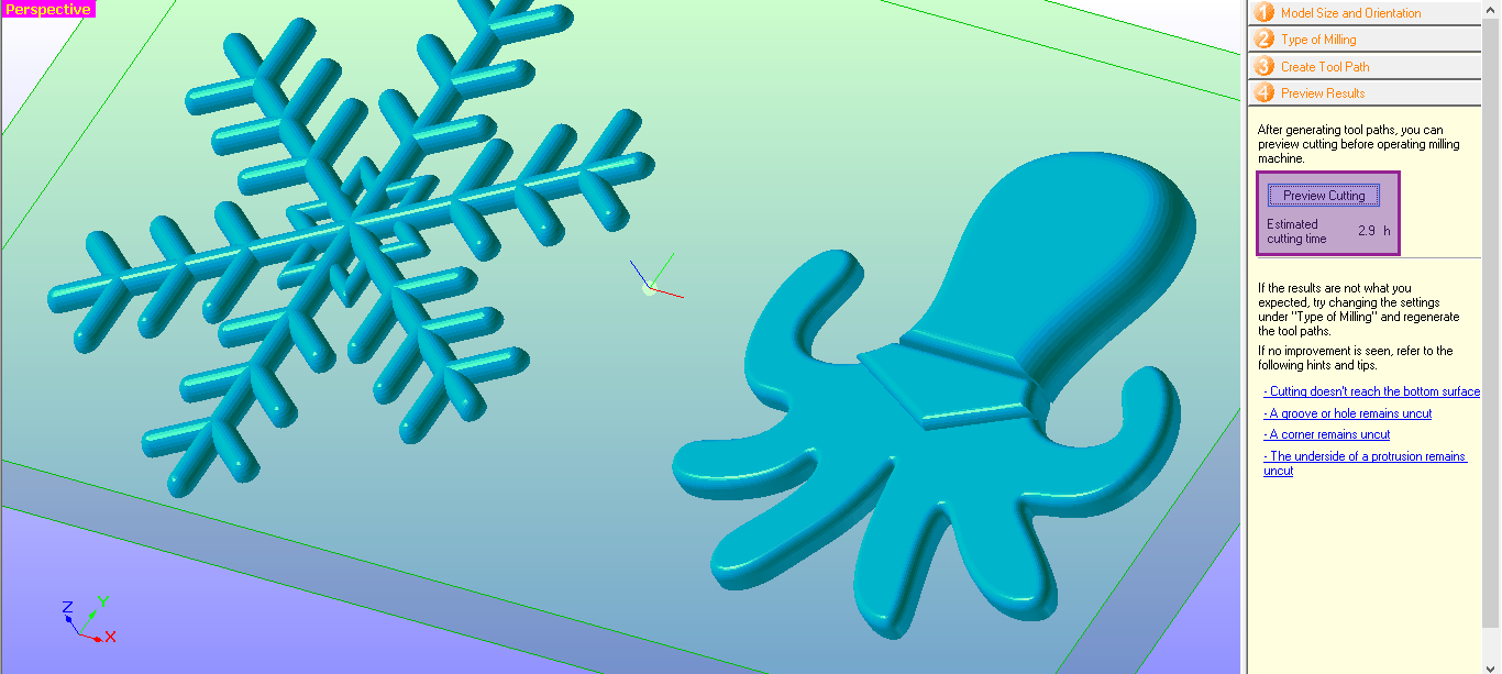
Finally, we can now preview what the mould will look like at the end of milling to ensure it is exactly how we want it to be.
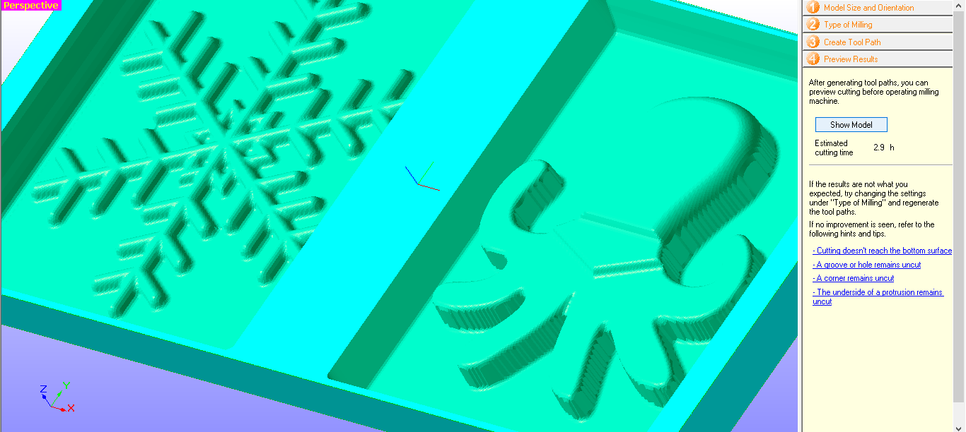
We can see that this will take a total of 3 hours to fully complete.
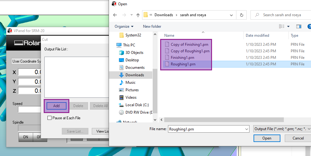
We can now save the output files to be able to load them into the VPanel that will download them to the milling machine.
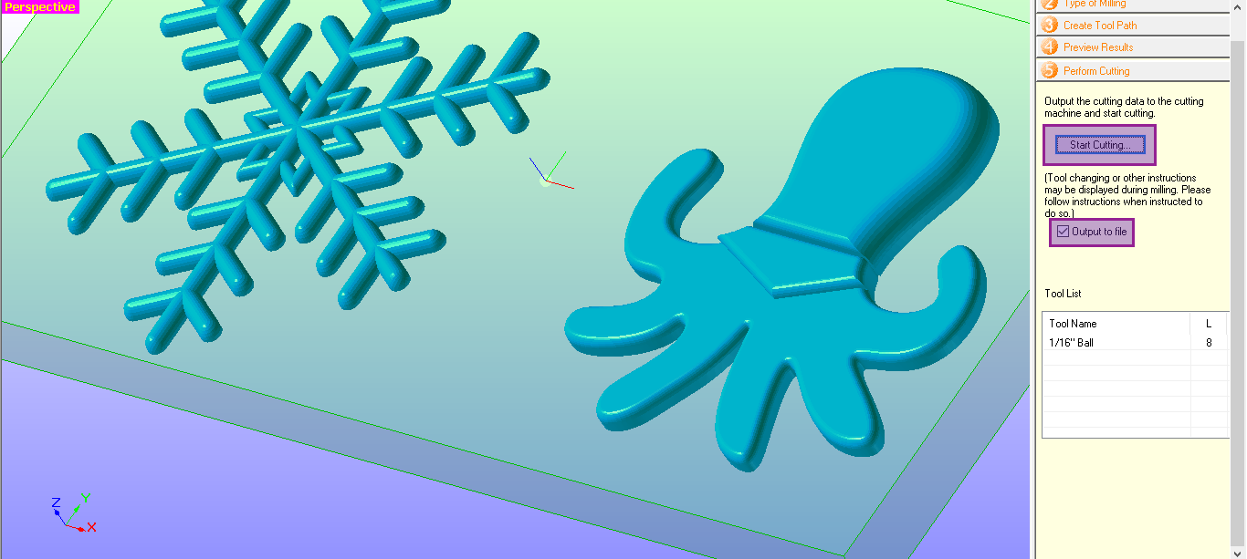
We can now load the files into VPanel. We can either select all of them, or just one at a time. The benefit of having control over this is to ensure that you can break up the milling time by having it complete smaller tasks and stop, but also to monitor each task once they’re completed to make sure it’s doing everything correctly.
VPanel will give continuous updates about the current milling task.
Once everything is done, we can finally start milling!
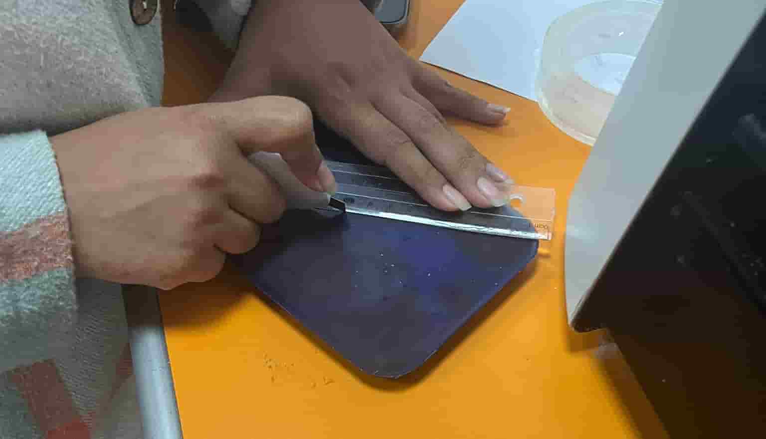
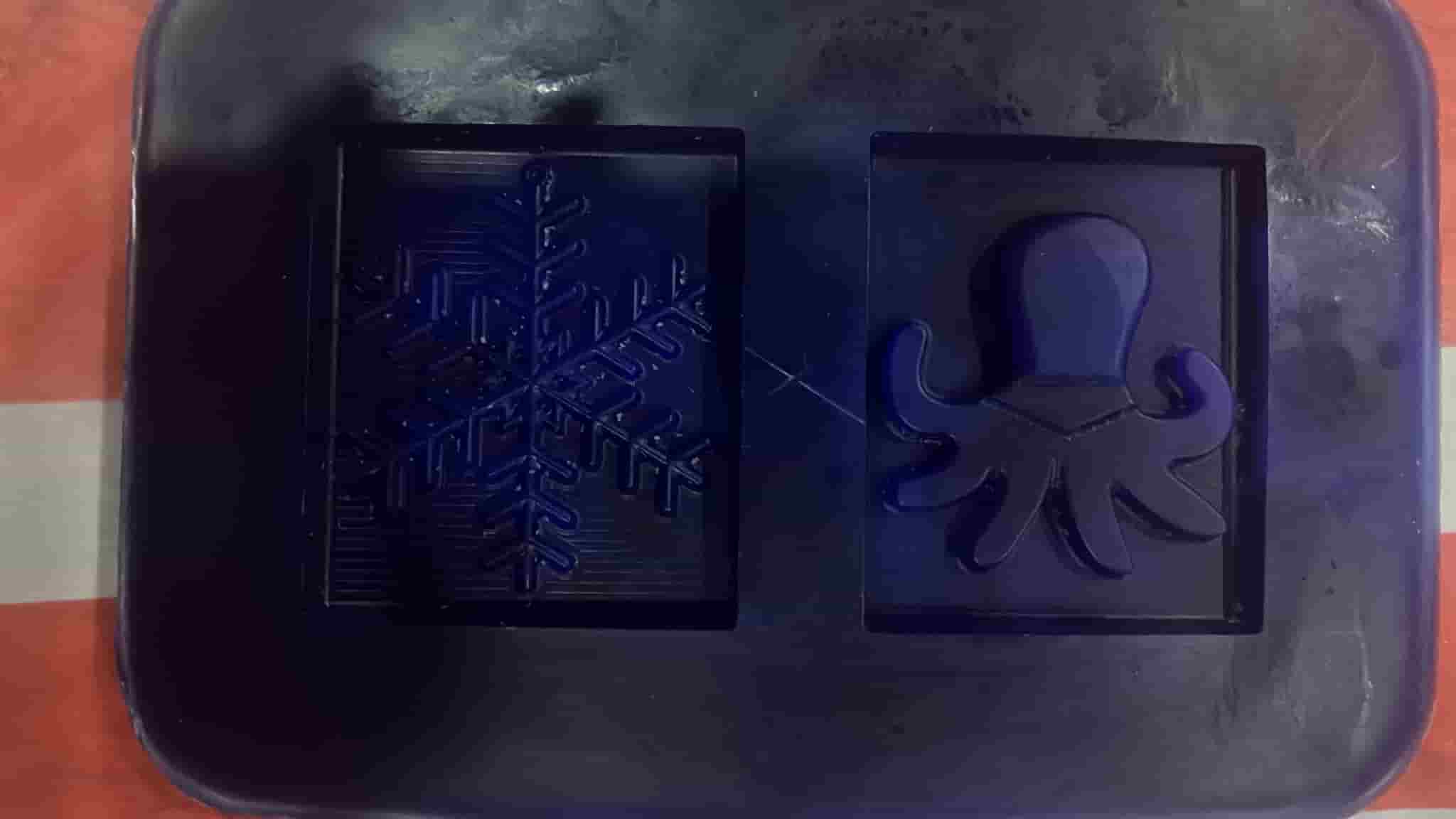
This is how it turned out after it was done milling and was cleaned off!
Step 3: Making an Octopus Silicone Mould
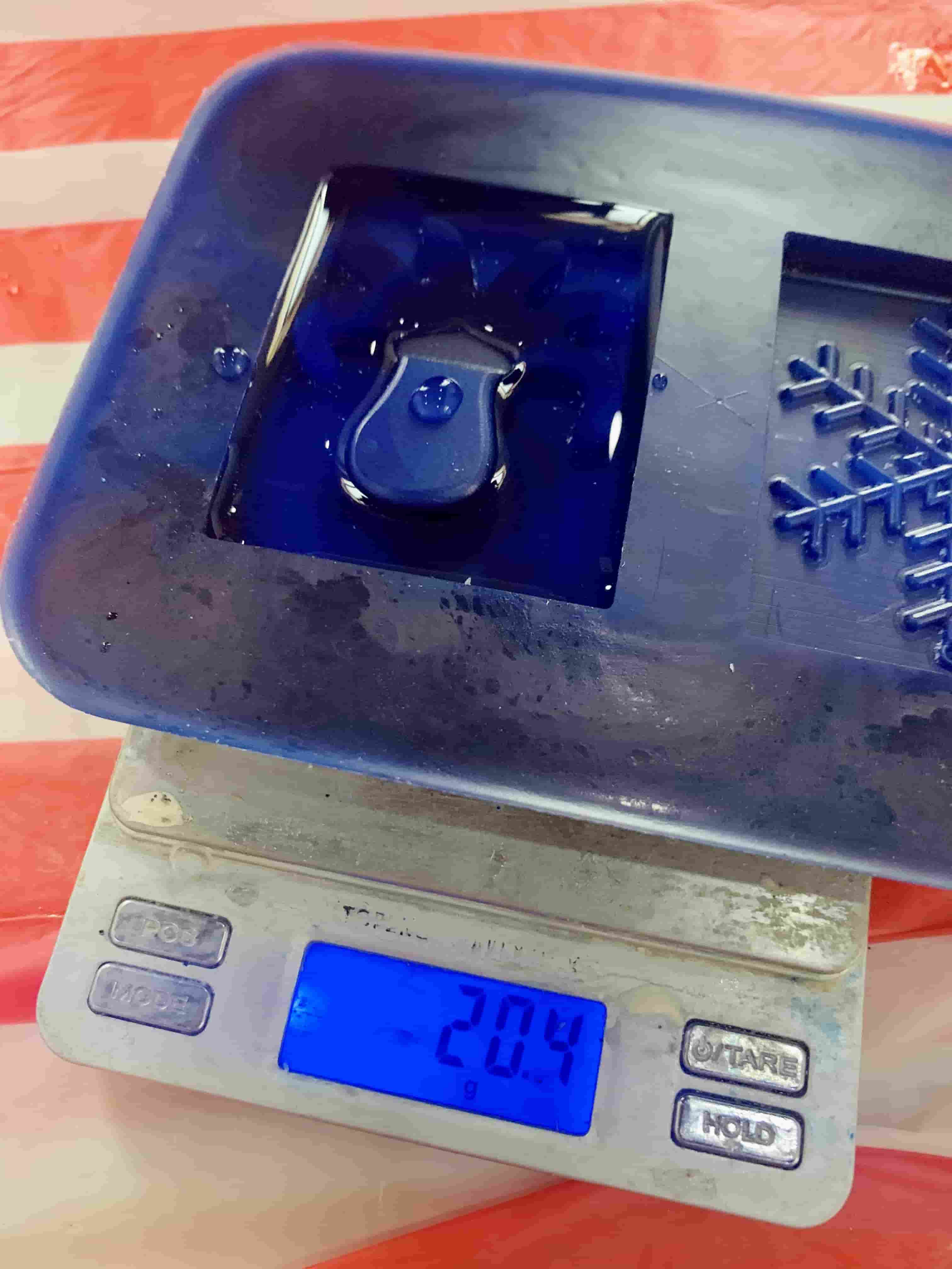
First, I filled the mould with water to measure approximately how many grams of the silicone mixture I’ll need. Since it turned out to be approximately 20 grams, I rounded it up to making a mixture of 30 grams.
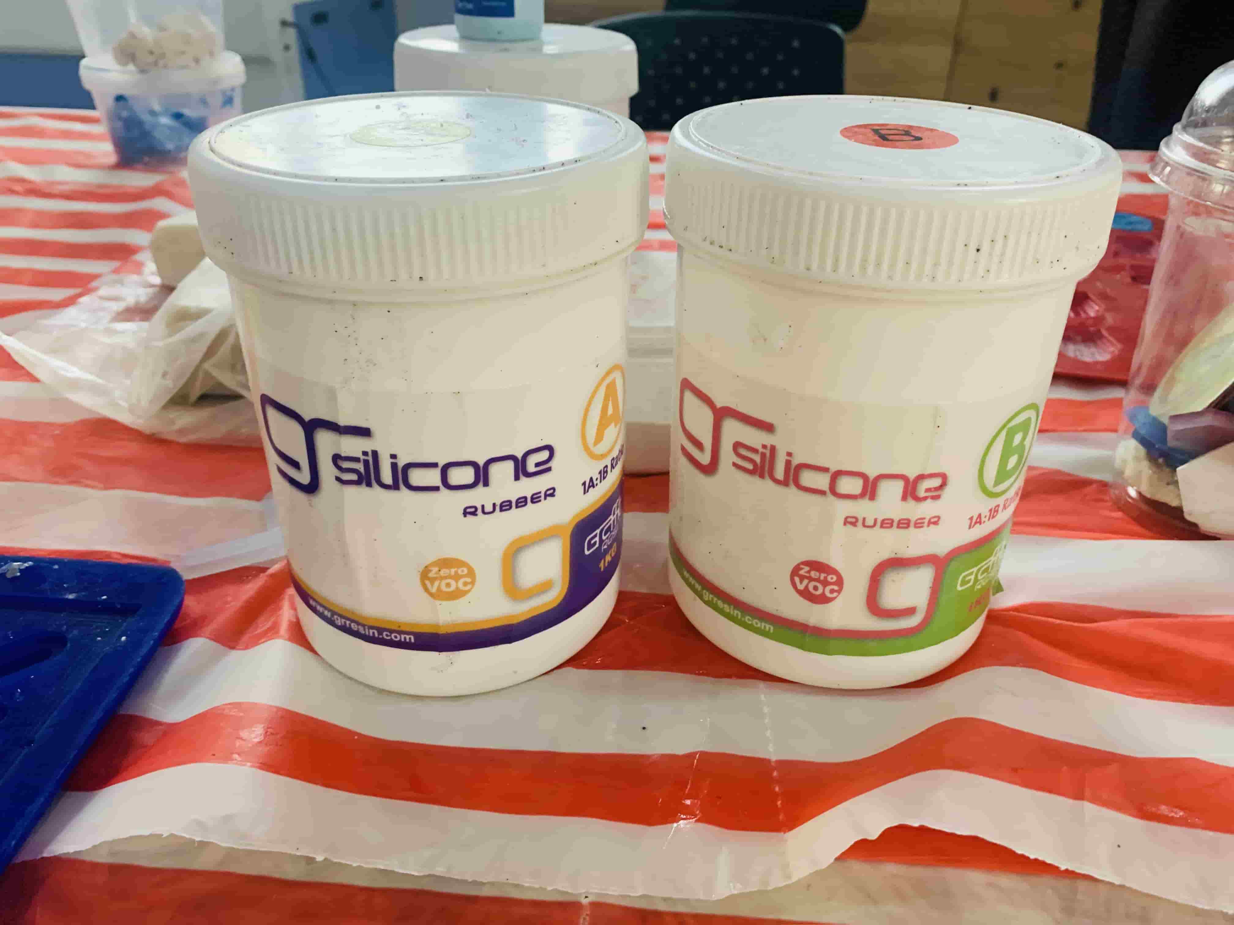
These are the A and B bases I’ll be combining with a 1:1 ratio to make the silicone mixture.
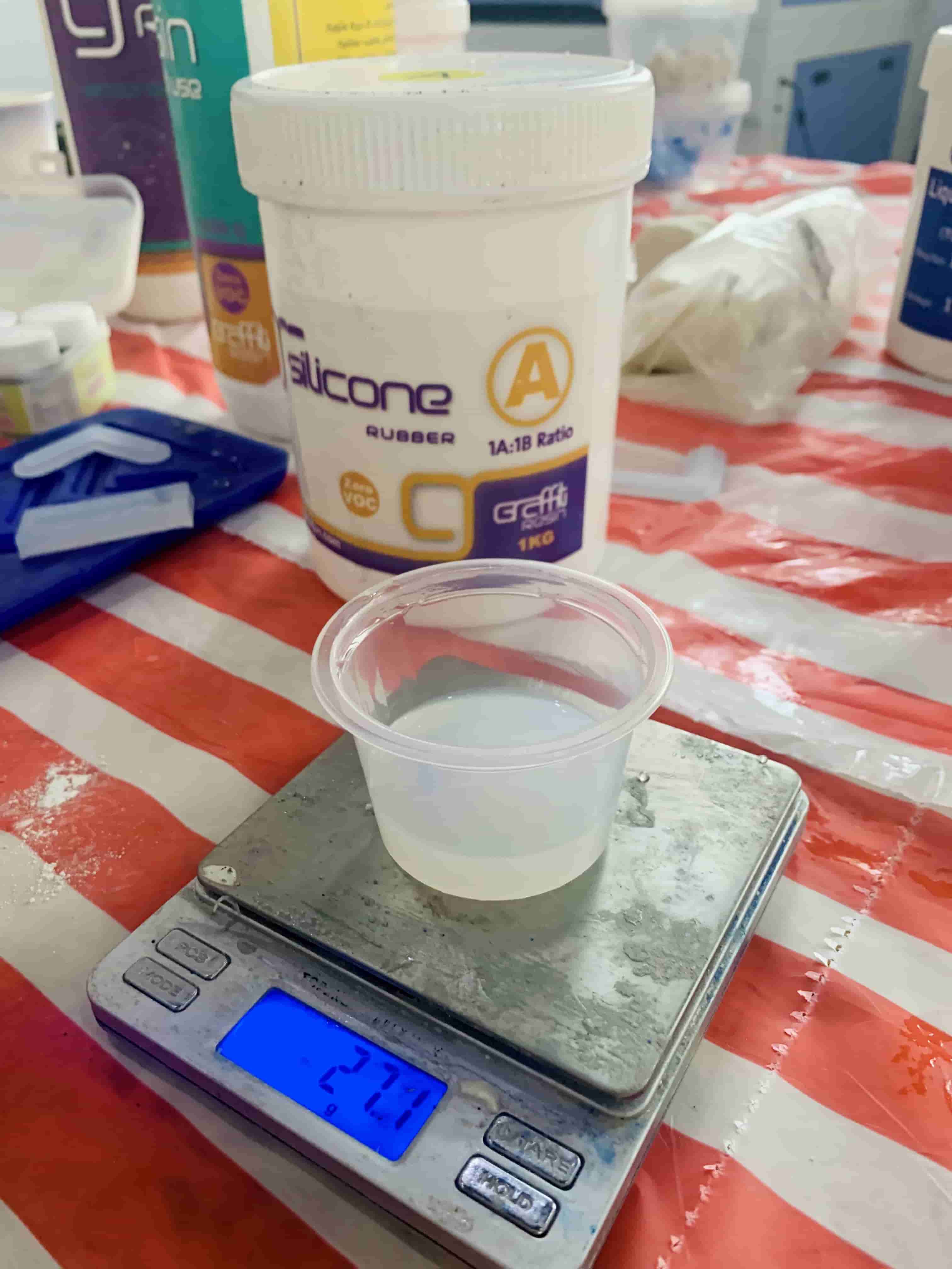
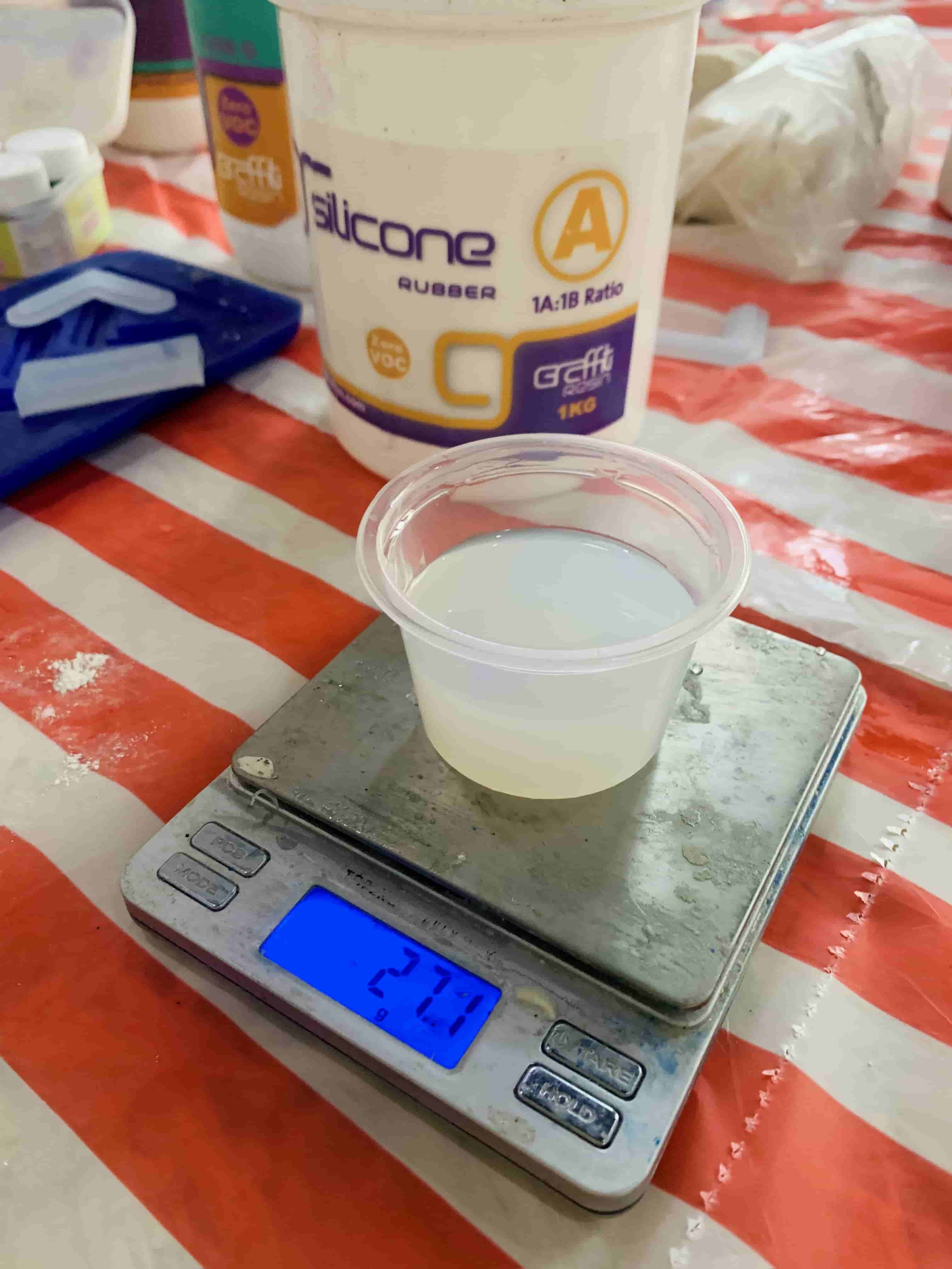
I poured out and measured both to have them in equal parts.
Note
The mixture was doubled because I made this approximately 60-gram mixture with my partner to fill both our moulds.
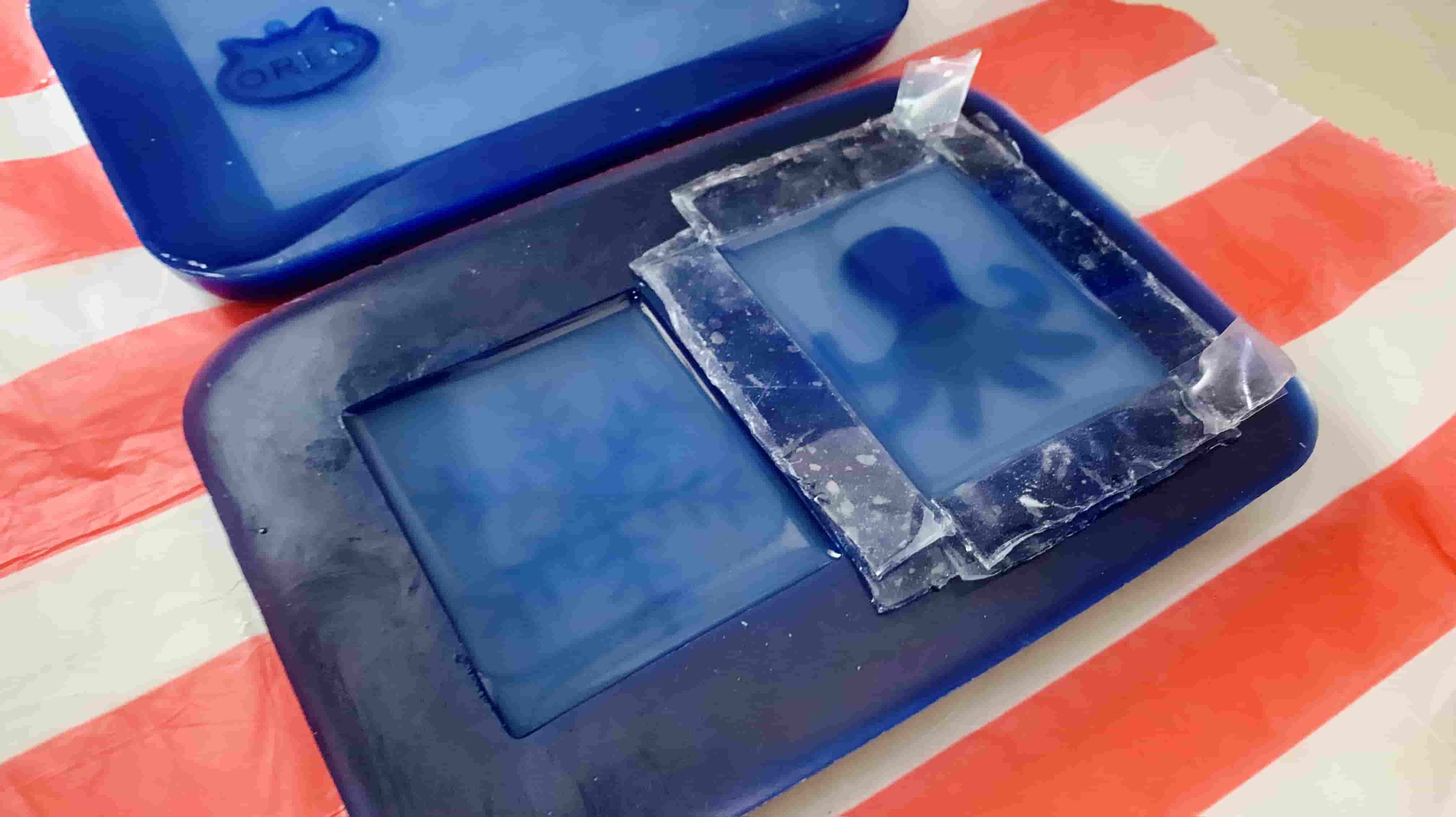
I then stuck on two layers of thick tape to the borders of my milled out design, because as we can see in the photo of it being filled with water, the head of the octopus is too high to be fully submerged in the mixture. The tape will add additional height to fully cover the octopus.
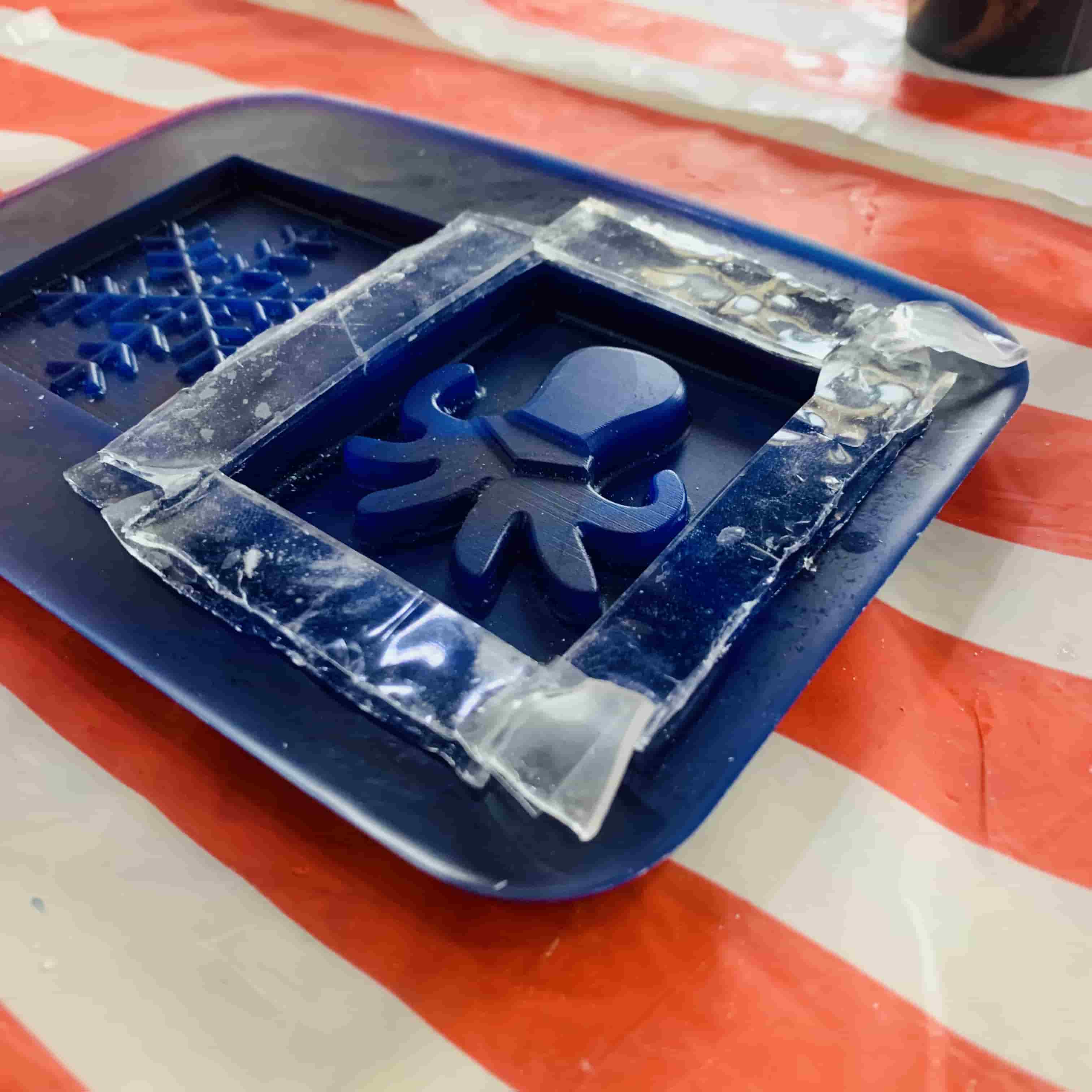
I then poured in half of the mixture until past it completely submerging the octopus. I ensured that I did not over-pour so that our designs are not accidentally attached.
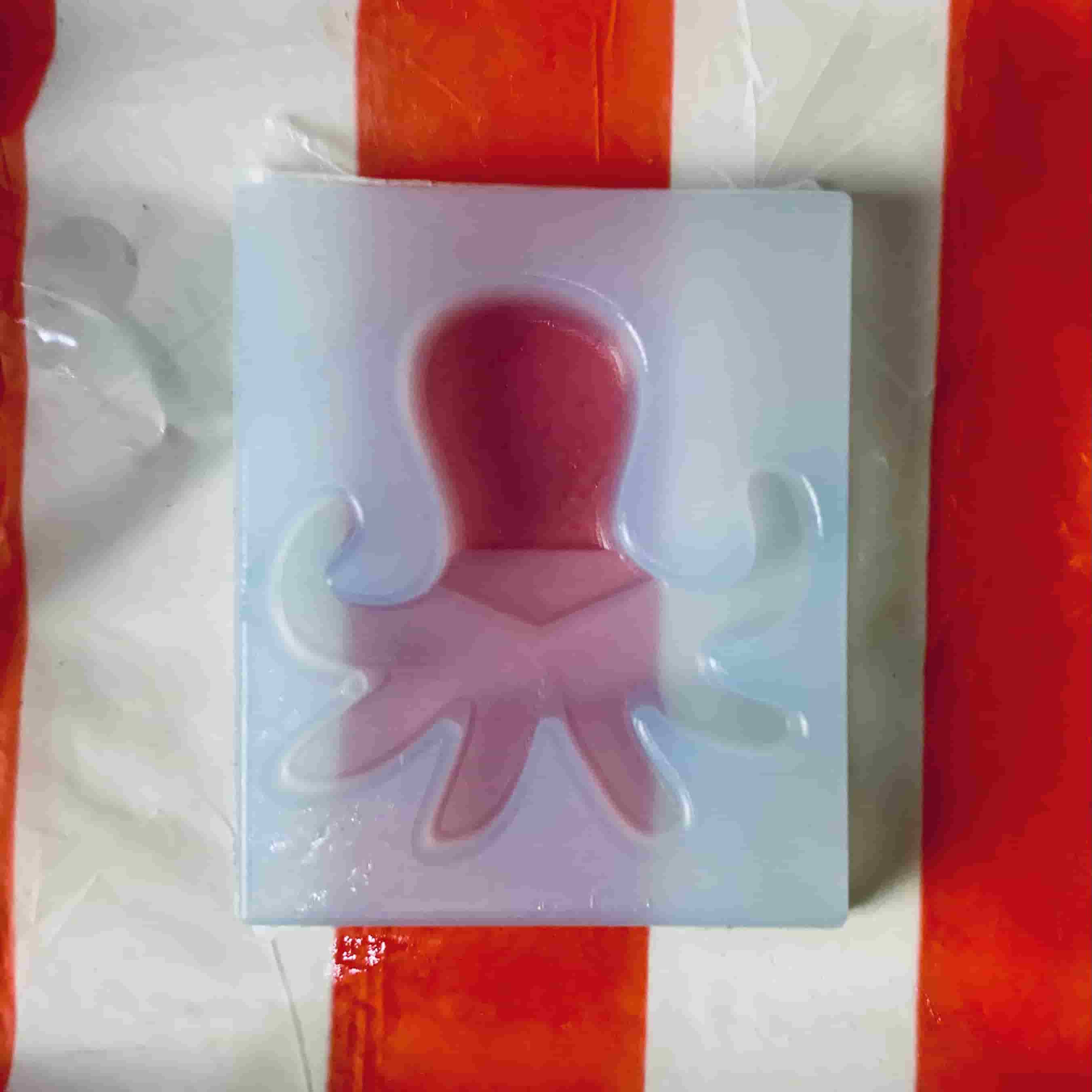
The curing time for the silicone is normally around 8-12 hours, but due to colder weather, I planned to leave it for 24 hours. I felt as though it was not completely cured by then, so I left it for an additional couple of days. This is what it looked like when I popped off the mould. It’s now ready to use to cast!
Step 4: Making a Resin Octopus
I decided to cast my octopus with resin, because I wanted to add some colour and sparkle to my end product, and I knew from the group assignment documentation that resin has a longer working time, so I can take my time to work with it.
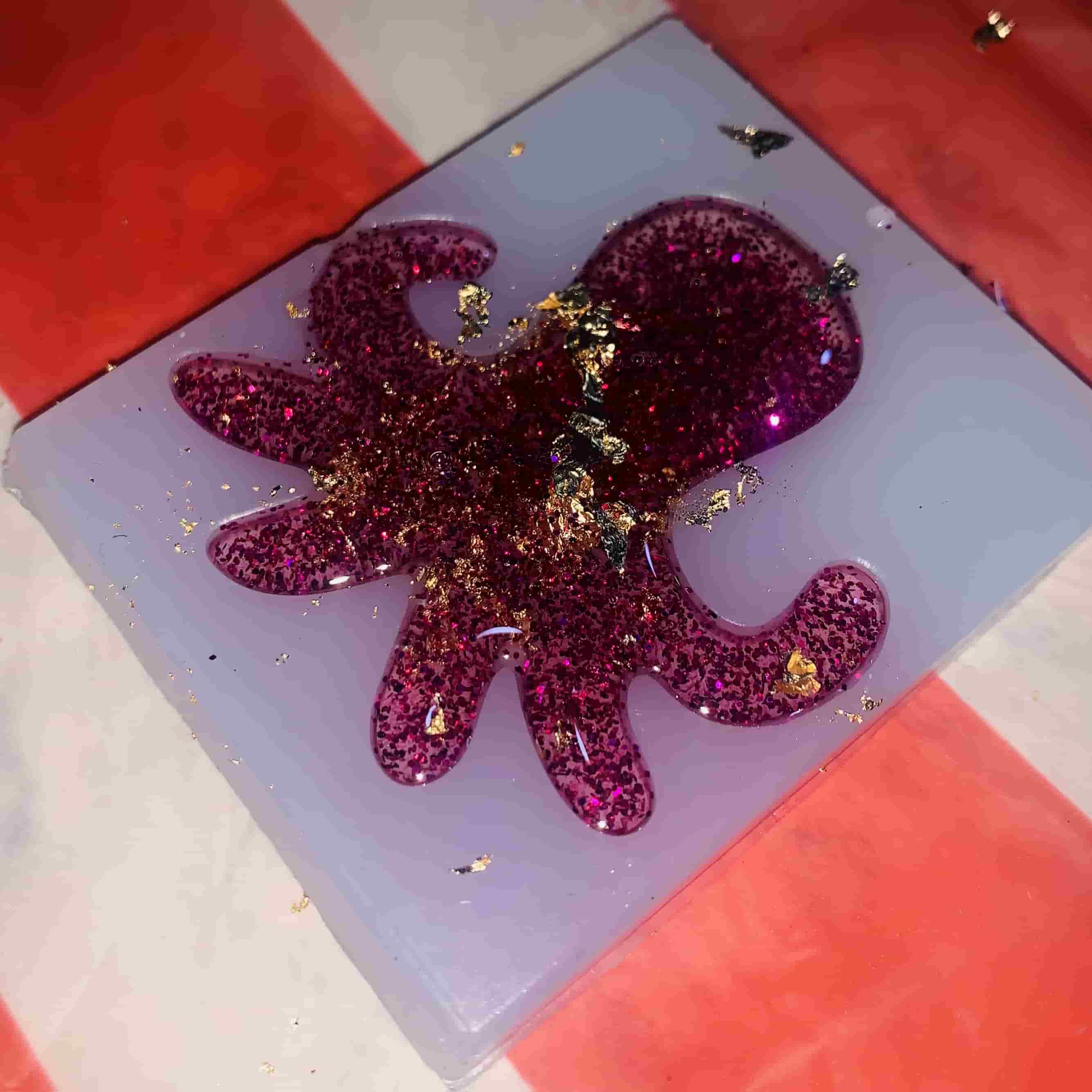
I mixed equal parts of the resin and resin hardner (a 1:1 ratio) for approximately 5 minutes. When I ensured the mixture was fully mixed, to add colour and shine, I then added purple glitter and gold flakes to the mixture and mixed thoroughly again.
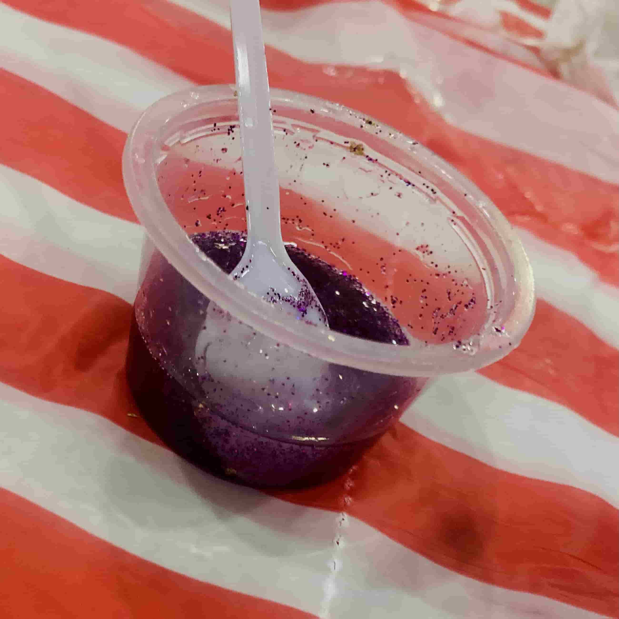
I then filled my octopus mould with the resin mixture, and broke up and layed more gold flakes on top.
The curing time for resin is 8-12 hours, but based on the *documentation*, it is better to wait an additional 24 hours to make sure it is fully set and hardened, so I did that.
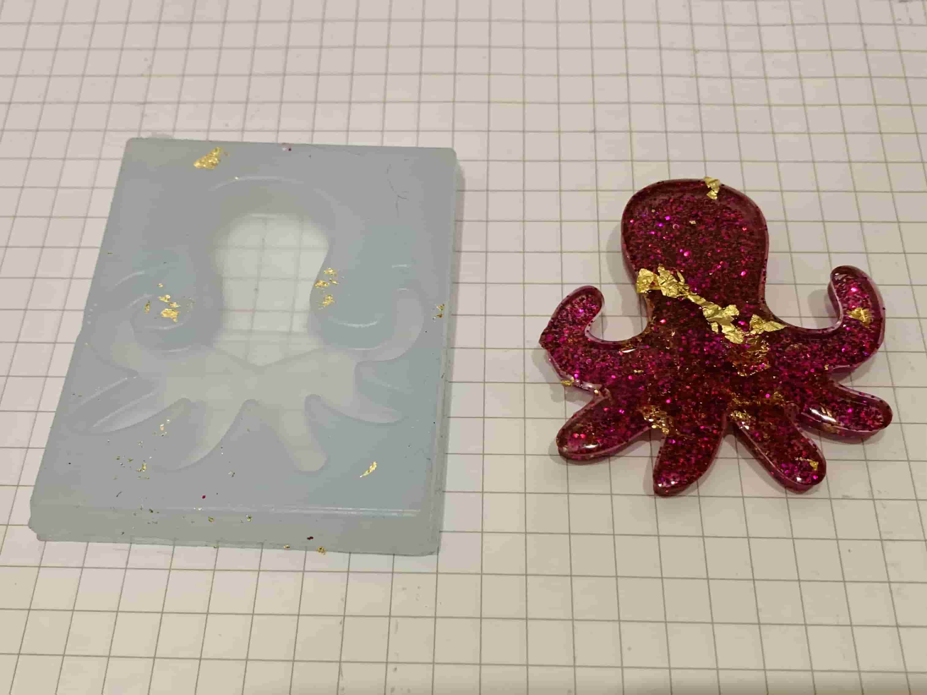
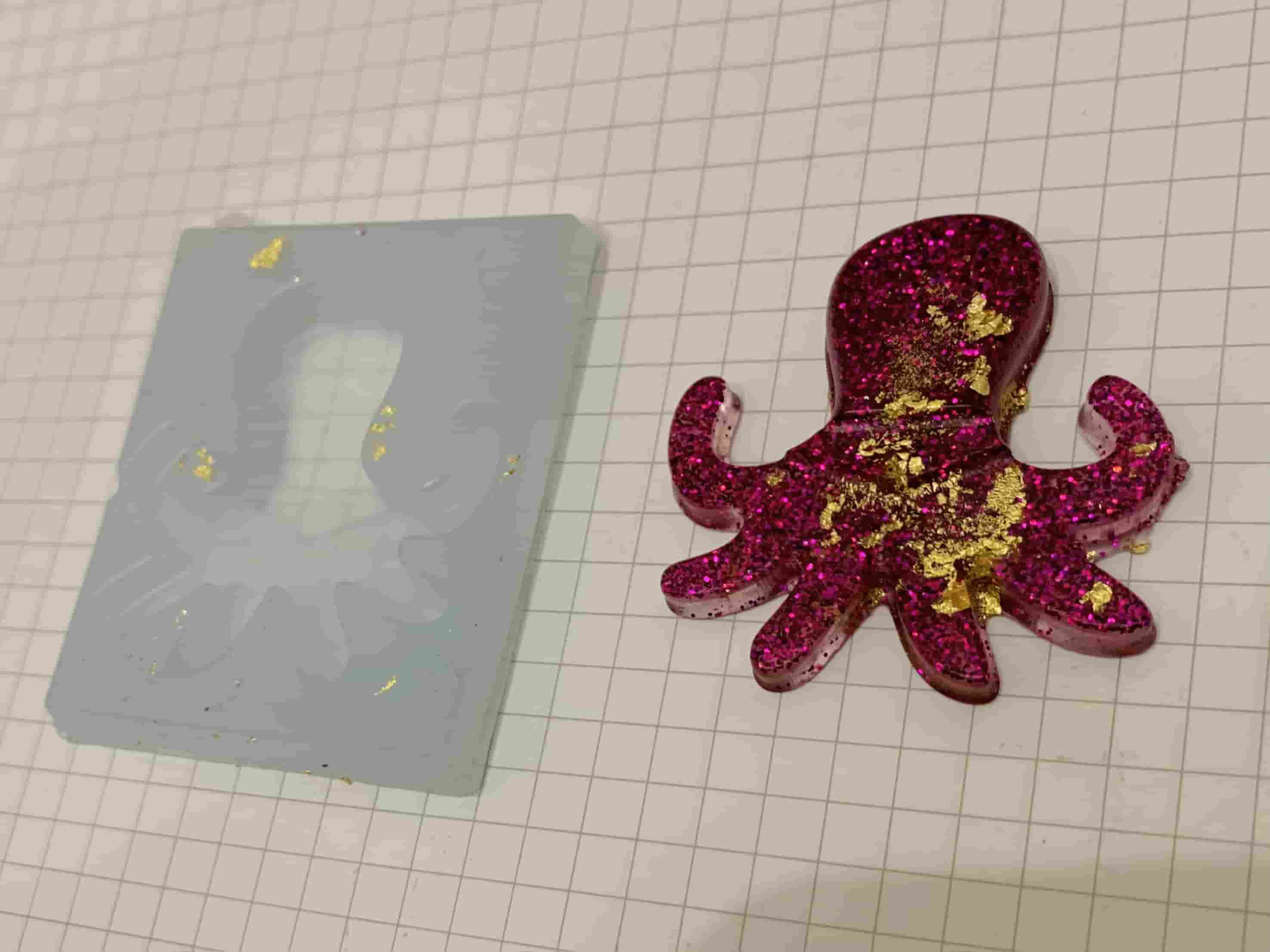
After a couple of days, I tested if my resin was fully set by gently tapping it with a plastic soon, and found that it was solid!
I gentled popped off my cast by bending the flexible silicone mould until it released it. This is how my glittery resin octopus turned out!