Week 5: Computer-Controlled Machining
This week we learned how to design and CNC cut furniture, and work with plywood for sanding and finishing.
Facts About the Machine
CNC Milling Machine
Computerized Numerical Control (CNC) Milling Machines are large-format engineered machines used to mechanically cut away at a workpiece into a desired shape. This process can be used with a variety of materials, including plastic, metal, wood and glass.
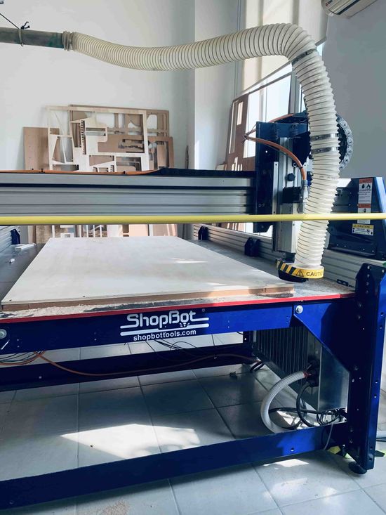
It uses a rotating cylindrical cutter to move along multiple axes, and create slots, holes and details in material to turn it into the defined shape that we give it, using DXF files and toolpaths to define each of these elements of what should be cut.
CNC Milling Bits and Cuts
CNC Milling Bits are the drill bits that are the cutting, carving and engraving that actually perform the cutting of material. They come in different shapes and sizes, more than we will be listing below, but not all of them are necessary to use for every application.
| Type/Shape of Milling Bit | Milling Uses | Appearance |
|---|---|---|
| Square/Flat End Mill | Roughing, side milling, slotting, profiling, and plunge cutting | 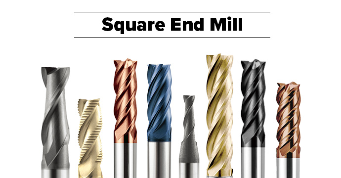 |
| Ball Nose End Mill | 3D carving, contour milling, shallow pocketing and contouring applications | 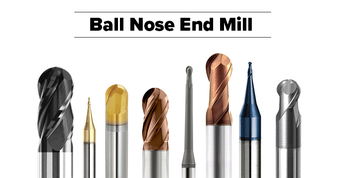 |
| Corner Radius End Mill | Corner milling for flat-bottom pockets and rounded contours | 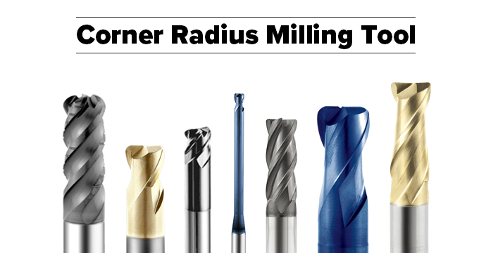 |
| Taper End Mill | Mill grooves, holes, or side-milling with a slope angle | 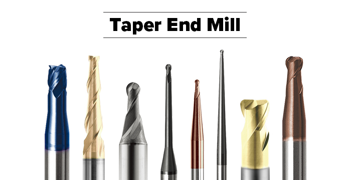 |
| Long Neck End Mill | Mill deep slotting (deep pocketing) | 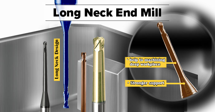 |
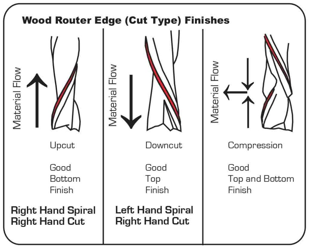
In addition to there being different types of milling milling bits, there are also different types of milling cuts, which refers to the finish on the edges of where the material is cut.
The different milling cut types include:
| Type of Milling Cuts | Function |
|---|---|
| Upcut | Tears the top edge of the wood and removes chips in an upward direction |
| Downcut | Pushes the cut wood downwards, which gives a smooth top edge, but a torn bottom of the cut |
| Straight-cut | Not angled to the cutting surface and provide a balance between downcut and upcut tools |
| Compression | Has few millimeters length with upcut and rest with downcut, so you can achieve upcut or downcut by controlling the depth of cut End up with smooth upper and bottom edges on the wooden workpiece |
Info
To learn more about other router bits, and for other projects, such as CNC carving, check this out as well as this.
Safety Precautions
Since CNC Milling Machines are large-format machines that work on a large-scale, and also use drilling tools, it can be very dangerous to operate, so we must be very cautious to handle it.
Here are some important rules to abide by while operating one of these machines:
Warning
Please READ and LISTEN to safety instructions before operating a CNC machine. NEVER operate a CNC machine alone.
- Wear proper eye and ear protection using safety glasses or goggles and ear muffs.
- Wear closed-toe shoes.
- Do NOT wear loose clothes with loose long sleeves, and ensure your sleeves are rolled up.
- Do NOT wear gloves.
- Do NOT wear jewellery, especially not long earrings and necklaces.
- Tie long hair back and tuck back the end of a hijab.
- Stand a distance of at least 1 meter away from the CNC machine while it is operating.
- Be careful when loading in tool bits and when operating a drill.
- Do NOT leave the machine unattended while it is operating.
- Do NOT put your hands anywhere near or on the material or the machine while it is operating.
- Ensure that the vacuum is running while the machine is operating.
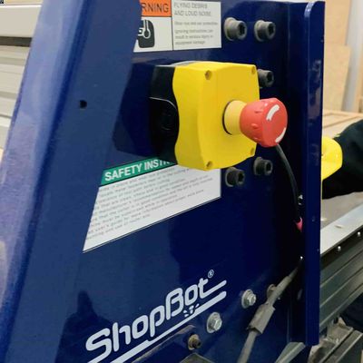
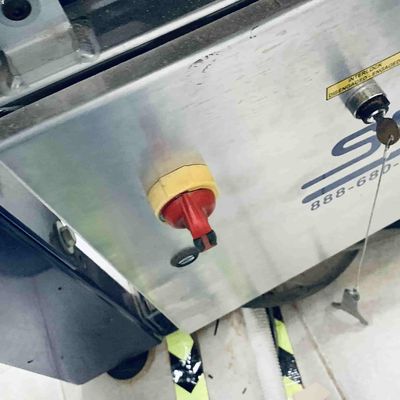
Warning
In case of any emergenices, you must STOP the CNC machine as soon as possible. There are two dedicated buttons to shut down the machine itself, as well as a dedicated button to stop the cutting operation. All are pictured below.
Materials: Engineered Woods
Engineered Woods are man-made materials made by binding pieces of real wood, scrap wood, shredded wood fibers and/or sawdust with adhesives to create products that look and act like wood, but are designed to be stronger and more durable. We’ll only be using engineered woods for our CNC projects, but it’s important to consider which of them are a best fit for each project.
| Type of Material | Material Details | Features | Finishing |
|---|---|---|---|
| Plywood | Made from multiple thin sheets of wood that are glued together to form a layered structure | Low cost Lightweight Does splinter and break easily Rough finish on edges Less susceptible to water damage |
Face of the plywood (not the edges) is smooth enough to varnish and paint Voids and holes need to be filled with wood filler before Splintered edges need to be sanded thoroughly, starting from lower grits, and with rougher handling |
| MDF | Made from broken-down hardwood and softwood residues by combining them with wax and resins | Lower cost than plywood Denser (heavier) than plywood Does not splinter or break easily Smooth finish More susceptible to water damage |
Smooth surface is great for painting Can sand, but very lightly with higher grits or it will break apart |
Info
To learn more about other types of wood materials, including natural wood, and for other projects, such as CNC carving, check this out.
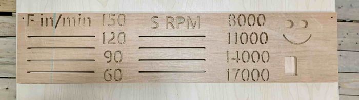
Group Assignment: Testing Alignment, Speeds, Feeds and Different Toolpaths
Our colleague Sara Hasan took the liberty of completeing the documentation for our group assignment this week. Check it out here. I will briefly go over the descriptions of what was testing in the assignment.
-
*Alignment The alignment of the CNC milling bit relative to the cutting material. Ensuring the alignment is correct will allow for smooth operations, cleaner cuts, and less damage to the material.
-
Speeds vs. Feeds Speed rate refers to the speed of the distance travelled by the machine, while the Feed rate* refers to the speed of the rotation of the spindle. These two operations happen simultaneously and must be adjusted according to the desired result.
-
Different Toolpaths There are two types of toolpaths we explored. First is the profile toolpath, which refers to the path in, around or on the outline of the shape being cut. Second is the pocket toolpath*, which refers to the creation of 2D pockets in a design, as used for CNC carving.
Individual Assignment: Bookshelf
Practicing Similar Designs: Laptop Stand
I was looking through the official YouTube channel of Autodesk, where they post many very thorough and educational tutorials on designing different projects on Fusion 360. I found a tutorial for designing a laptop stand that had similar features to my idea for a bookshelf with angled, sliding shelves.
Tip
If you’re still getting started with Fusion 360, following tutorials from their YouTube channel can be very helpful.
I followed the tutorial to practice a similar design to what I wanted to achieve, which allowed me to be familiar with some tools I hadn’t yet figured out how to use in my designs, that ended up coming in very handy when I finally started my own design. You can view my design below.
You can also download my design here.
Laptop Stand for practice on Fusion 360:
Sketching
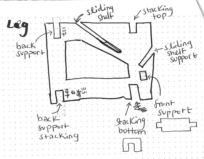
I started out by sketching each part of my design that I wanted to be in the bookshelf, but you can see later on in the design process, I added more parts, such as the supports later on.
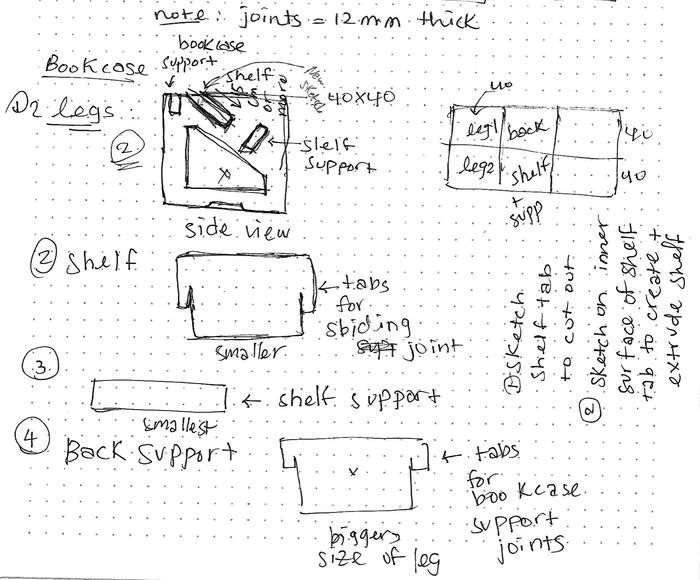
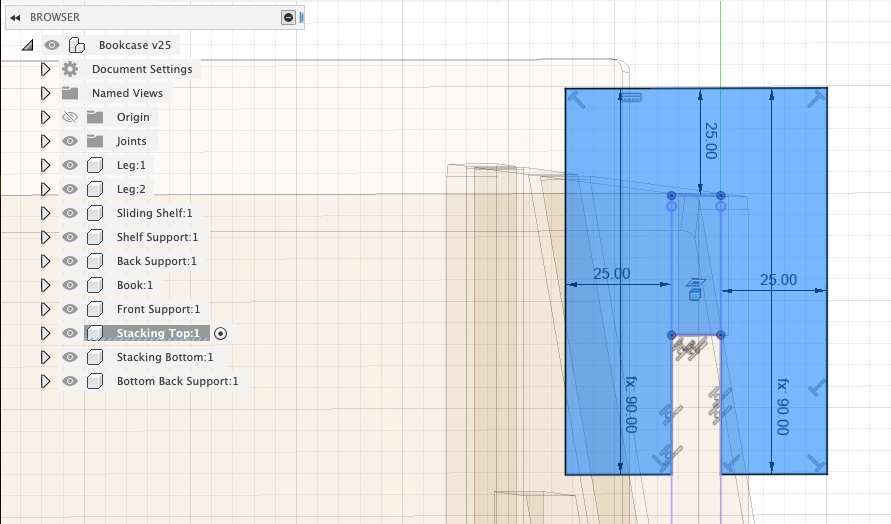
This was my update sketch for the leg since I had to figure out the cutouts for stacking my bookshelves together.
Tip
Sketching is a good way to get down everything you want to do for your design if you have a hard time visualising and keeping track of different tasks.
It does not have to be the exact design as you want it to be. Just start somewhere simple and expand on it later. Don’t overthink it!
Designing
Note
Note that I decided to make my design completely parametric, as I wasn’t sure if I wanted to change the dimensions of it later or if I was using the correct joint thickness for my pieces to fit yet.
I took the time to set each parameter, and use them when defining everything from the joint thickness, to the distance between the bookshelf legs, in case I wanted it to be longer later on.
This was my personal preference and I was comfortable with parametric designing after finishing the laptop stand tutorial, but if this won’t work for your own CNC assignment design, don’t worry about it. It isn’t necessary, as long as you have every element of your design in check and ensure there are no interferences between your parts!
Part 1: Creating the Main Parts of the Bookshelf
Refering to my sketch, the main parts of my bookshelf are: * Legs * Sliding shelf * Support for the sliding shelf * Back support for the legs.
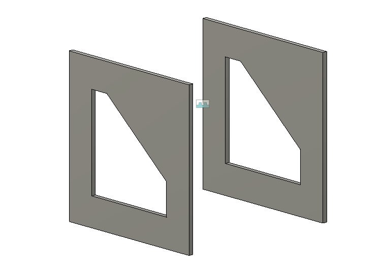
I started off by creating the legs, I wanted the void cutout in the middle of them to make it look more abstract, but also because:
- It would be slightly more lightweight, even though I already knew we were going to use lightweight plywood for this project.
- It would provide access to the empty space under the shelf, which is great for storage or adding something decorative to it if you’re using it as a single bookshelf!
Note
I personally liked that my pet bunny  used the cutouts as a little space to sneak in under the bookshelf!
When I finished sketching and extruding one leg, I duplicated it and created a joint between them that I set to a certain parameter distance. This is so I can control the distance between each leg if I wanted to, and it would in turn add length to shelves and supports I will add between them to make my design fully parametric!
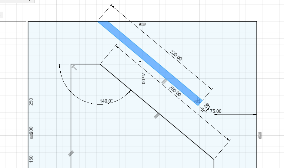
I then started to create the slot where the sliding shelf will go into. This shelf will be resting on an angle.
Note that I am sketching where I want the slot to be, which will be a cutout of the leg. I will be extruding this sketching and cutting through the leg. This is not a sketch for the actual sliding shelf!
Note
To avoid repeating the same operations on the second leg, roll back the Timeline to before you duplicated the leg. This will make it so any changes you make on the first leg will be duplicated on the second one.
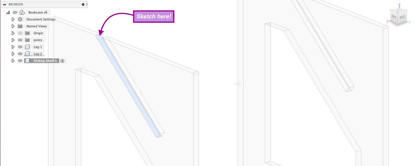
After creating the cutout slot, I can now start sketching the sliding shelf.
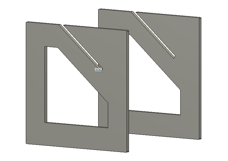
To do this, I will be sketching it on the surface of the inner slot. I am using this side, but you can use either inner side. The important thing to note is that you need to understand where this surface is resting for when you need to extrude it after.
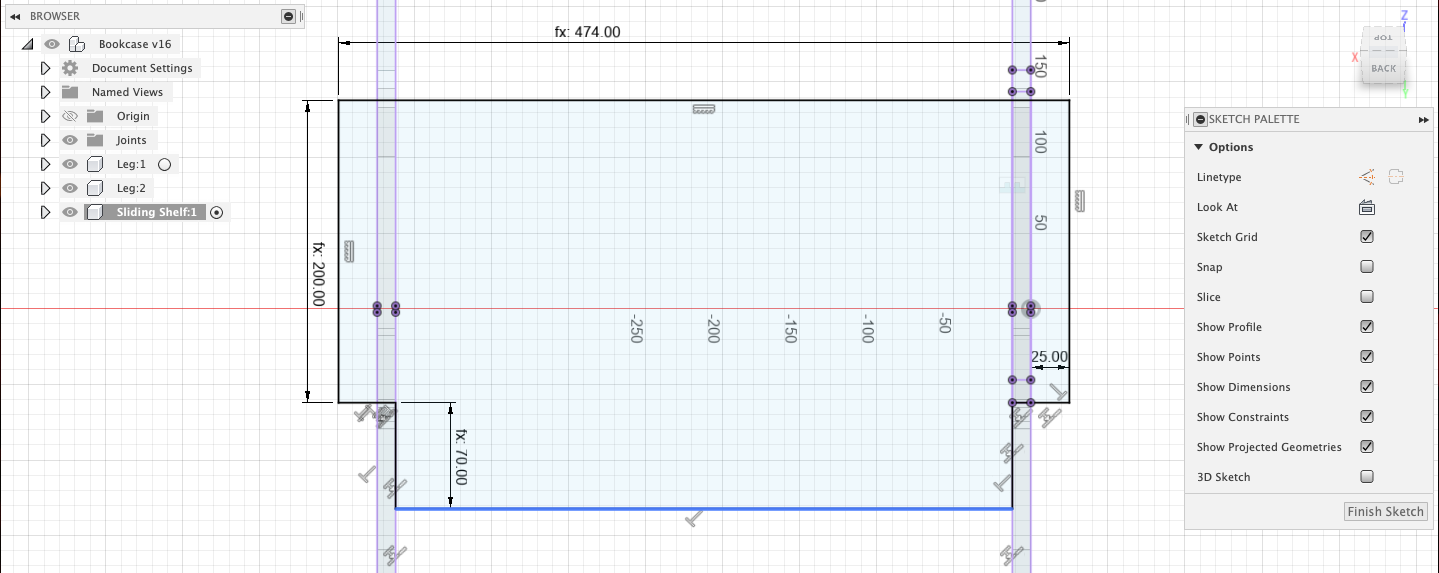
I then create the sketch for the sliding shelf. Notice that I use constraints and define the measurements for I want everything to be.
To make the design parametric, I also set the overall length of it to match the distance between each leg, so that it can be lengthened if I change the distance.
I then extruded the sliding shelf.
Tip
Creating separate components for each part of your design can make it easier to follow the timeline of each part separately. I did this for every part in my design.
I repeated the steps for creating the cutout slots for the sliding shelf support and the back support.
I then created the sketch for the back support on the inner surface of the slot I create, just like I did with the sliding shelf.
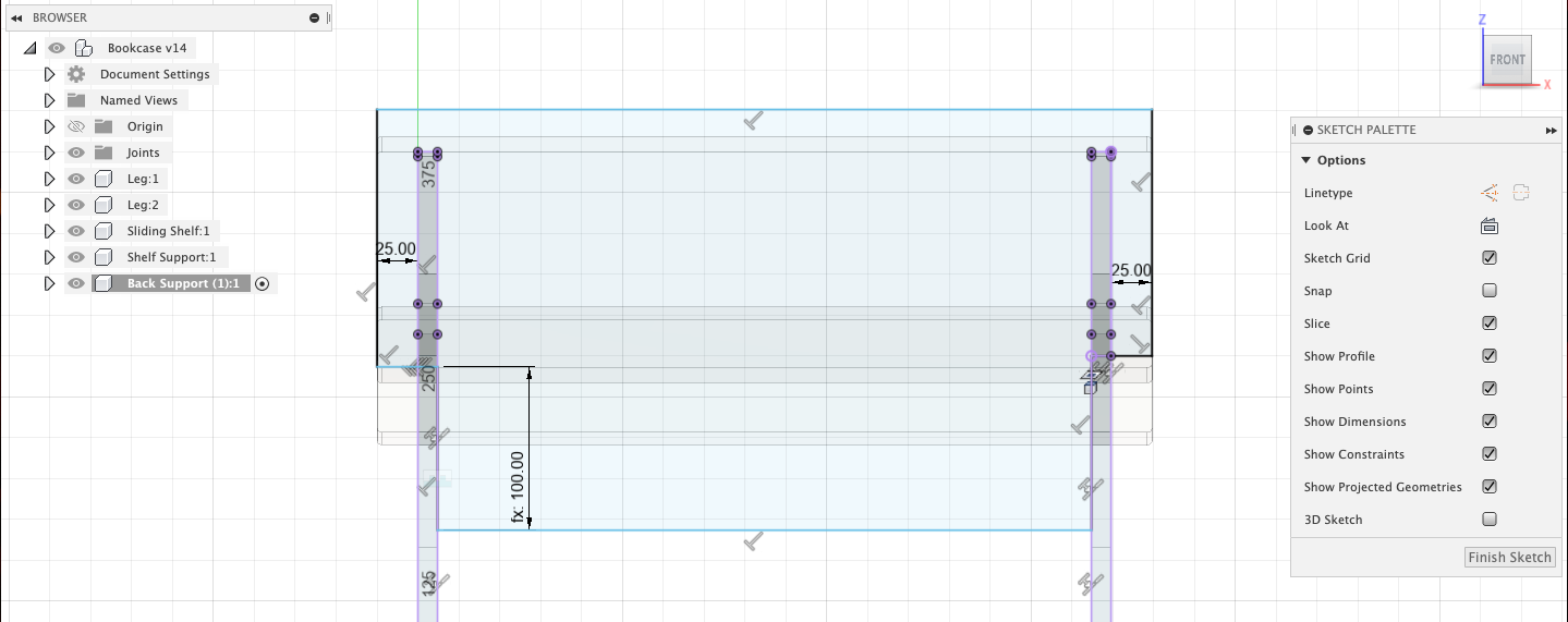
This is what the back support looked like once I extruded it.
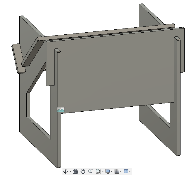
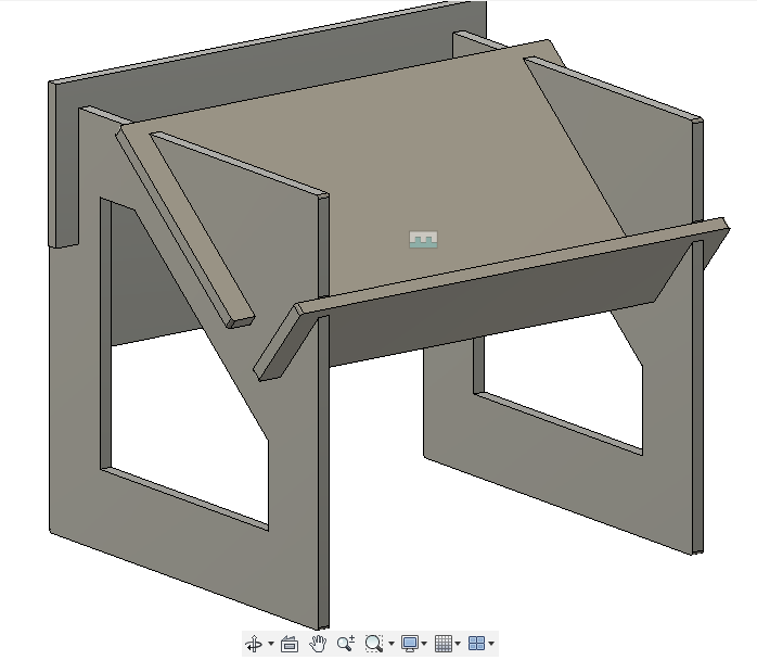
This is what the sliding shelf support looked like once I extruded it, then added fillets to the outer edges of each part.
Tip
If I were to repeat this design, I would add rounder fillets because these were too small for the CNC to replicate.
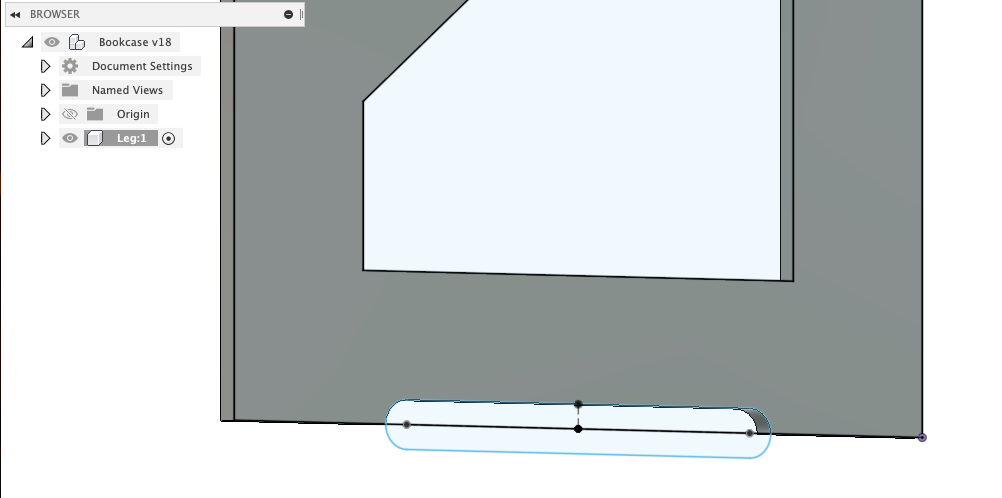
I also sketched and cutout slots at the bottom of the legs for them to stand and look better.
Part 2: Creating the Supports and Fitting Parts
At this point, I decided that because I created a very compact design for my bookshelf, that it would be perfect for being stacked! That way, I can CNC cut as many duplicates as I want that can then be stacked on top of each other to make a taller bookshelf.
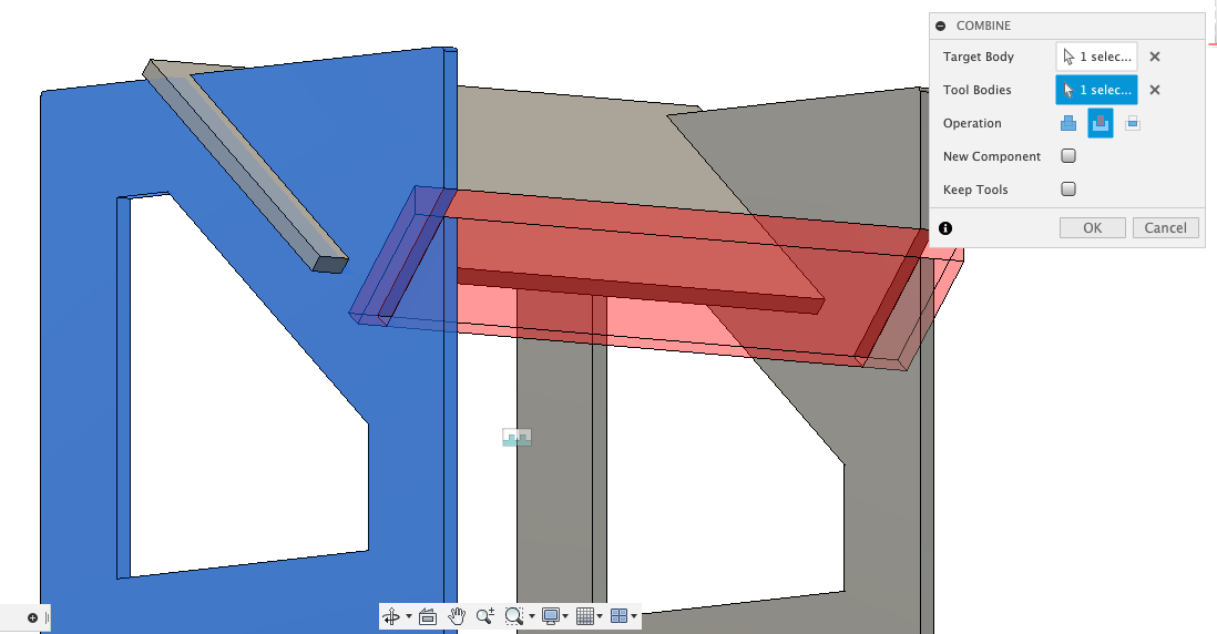
I started off by creating slots on the top and bottom edges of the legs. These slots will be where the back support on the backside and other smaller supports on the frontside will join together the bookshelves on top of one another when stacking them.
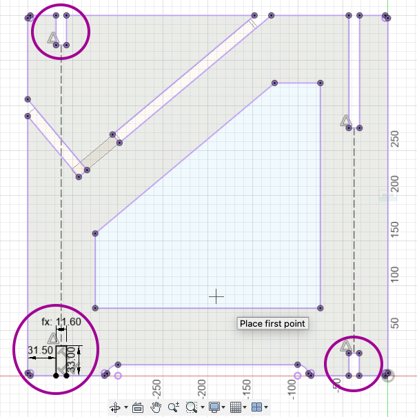
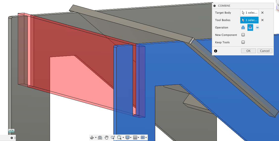
I then created a slot where I will have a front support going through the middle of the two legs, as I felt that the back support would not be enough.
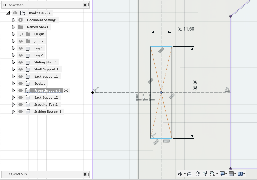
I then sketched out the front support that will go between and through each leg and extruded it.
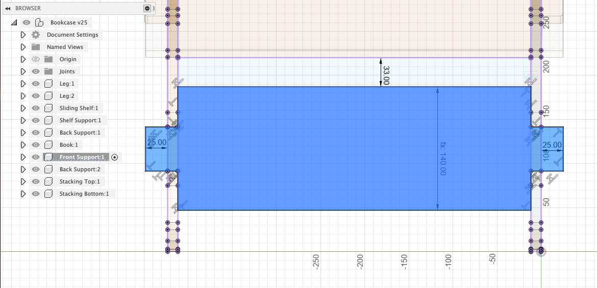
This is what it looked like after extruding.
I then sketched out the joining pieces that would go on either the top or bottom slots on the front of the bookshelf, depending on if the bookshelf was the lower or upper stack.
I made these small pieces just for the joinery and I did not want them to get in the way of actually putting in books on the shelf or mess with the aesthetic of the design.
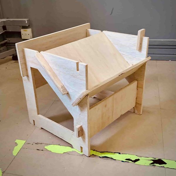
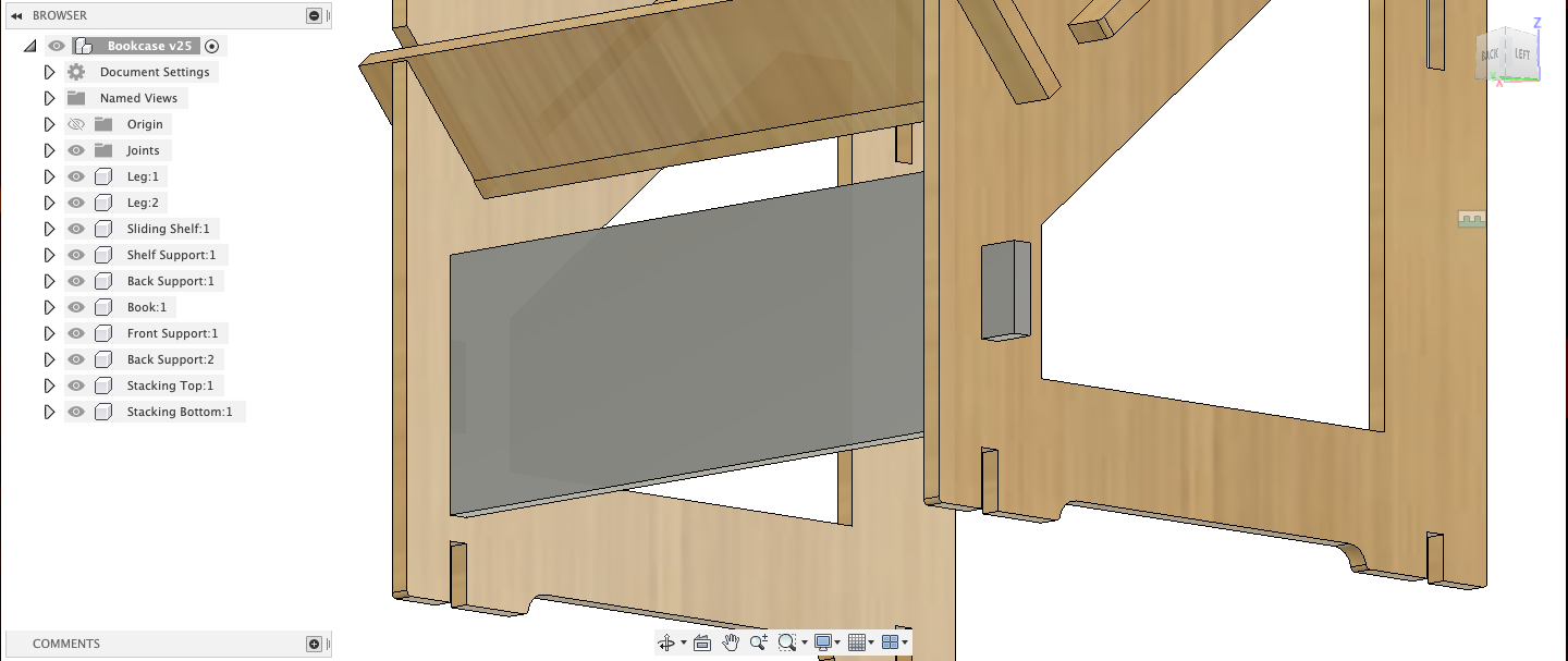
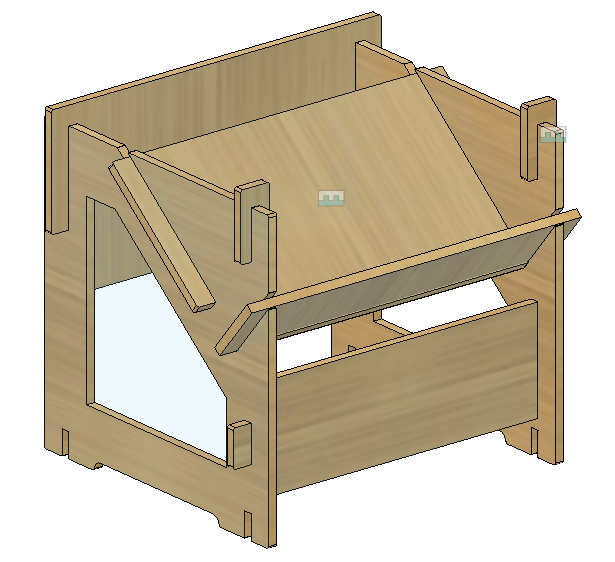
After extruding and filleting all the outer edges of the parts, this is what the final bookshelf looked like!
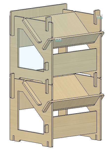
This is what the bookshelf looked like when stacked!
Note
I realised after that I could have made the front support less wide to show more of the open space inside the bookshelf, but this still looks good to me!
You can download my bookshelf design here.
The final design for my bookshelf on Fusion 360:
Part 3: Exporting the Design for CNC Cutting
To prepare my design for cutting, I laid out each piece flat, created sketches on each face and projected it to ensure that all the slots are exported correctly, then saved them as DXF files.
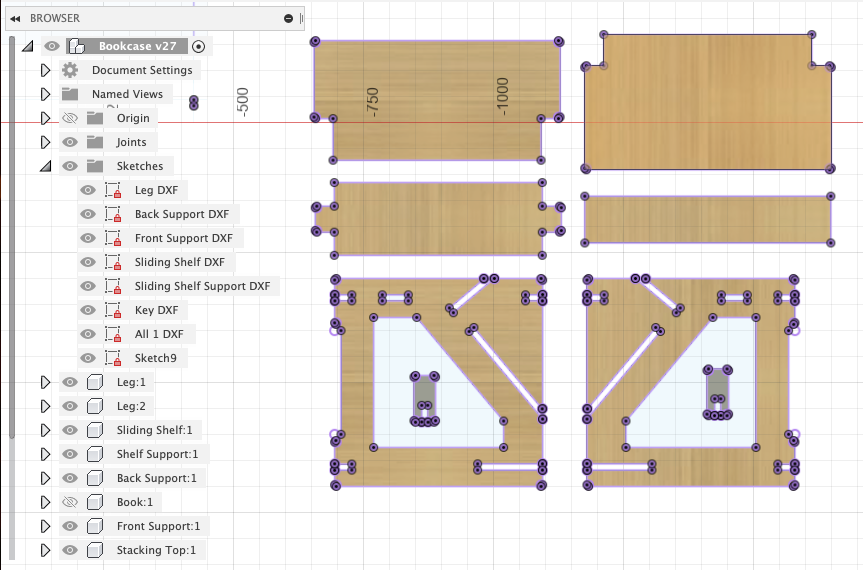
I realised after that it would be better to create a sheet the size of the plywood sheet we would be cutting on, which was 240 x 120 cm.
I was able to fit two bookshelves on this sheet, but I think later on I was able to fit in three. This was also exported as a DXF file.
Tip
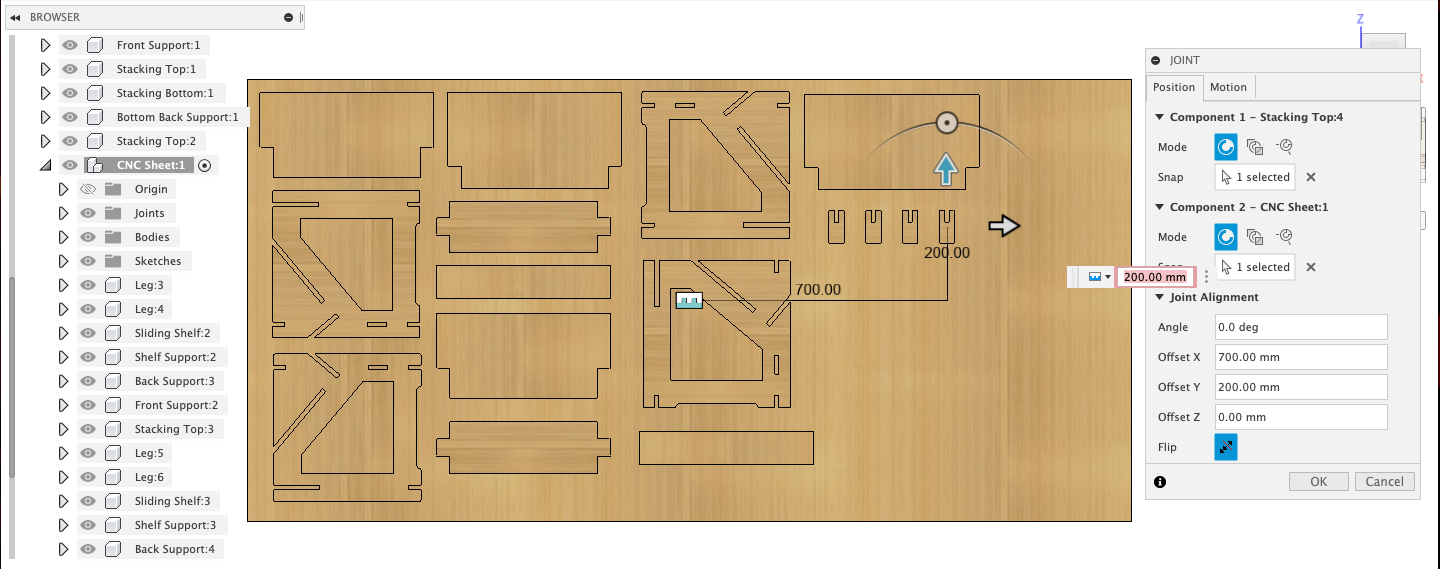
To create a CNC sheet, create a rectangle with the dimensions of the wood sheet you will be cutting on. Then have all the components you want to fit on it aligned flat and facing up.
To correctly align each piece to the face of the sheet, use Joint to create a joint between the sheet face and the face of your part. Then move it to a corner of the sheet. Rinse and repeat until all your parts fit on the sheet!
CNC Cutting
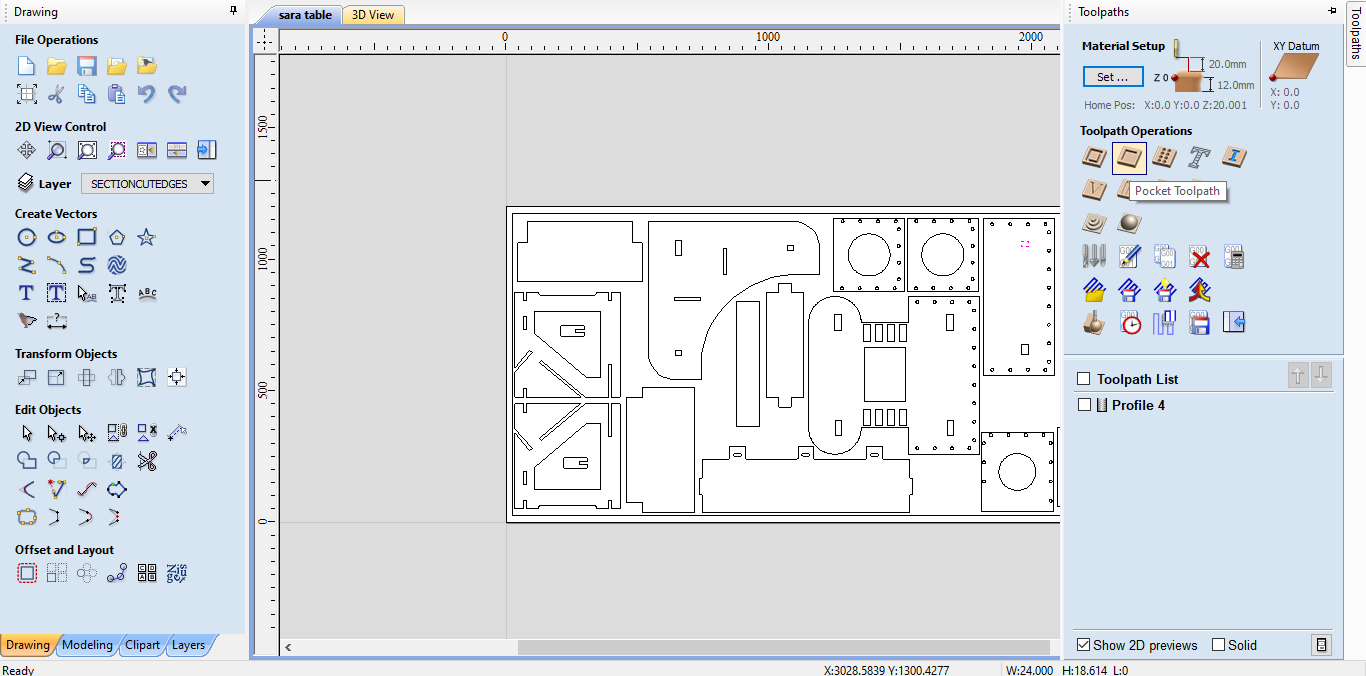
We started by importing and arranging our DXF files on the sheet (which has its dimensions already set to the dimensions of the plywood sheet) into Vcarve.
Note
I was only able to cut one of my bookshelves, you can see it on the left side of the sheet.
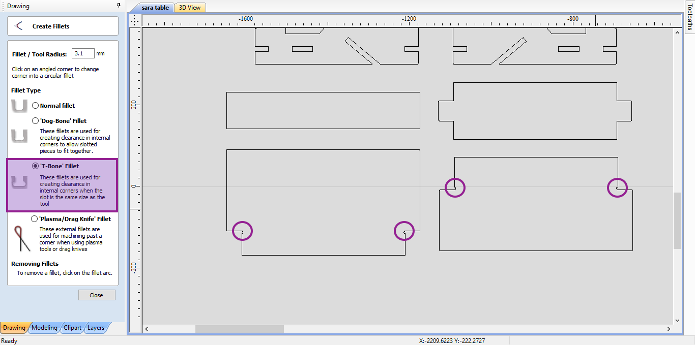
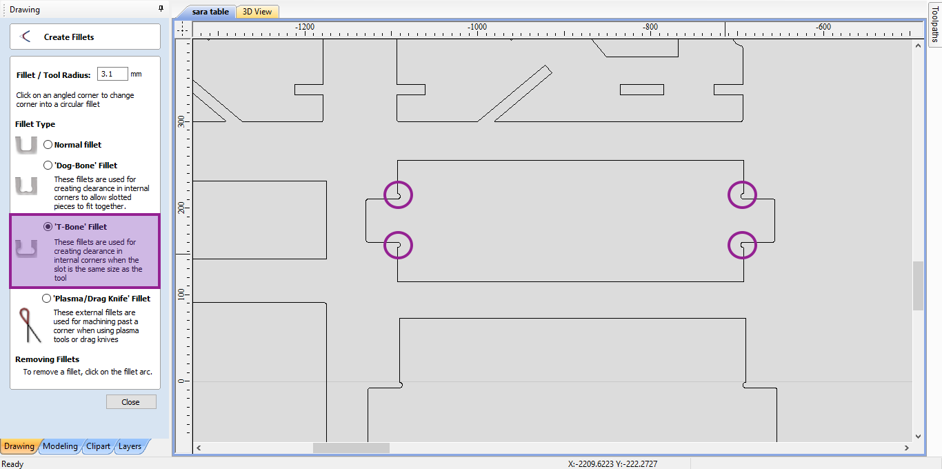
We started by adding T-Bone Fillets to the outer and inner joints and corners to ensure that they would be cut correctly.
Info
What are T-Bone and Dog-Bone Fillets?
These are types of fillets that create rounded corners instead of completely straight 90 degree corners in order to ensure that you’ll be able to complete join the pieces together. You’ll use either type depending on the type of joint you have, and whether it is internal or external.
Learn more about them here.
Also note that I repeated these steps with the internal joints and slots on the two leg pieces, but it is not pictured here. You can see it in the overall 3D generated sheet later on below.
This is the end mill bit that we are using for our CNC cutting. This must be defined in Vcarve to generate the operate toolpaths.
Notice that we define the toolpath, as well as the feed ans speed of the mill.
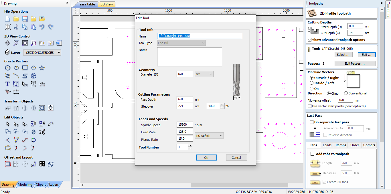
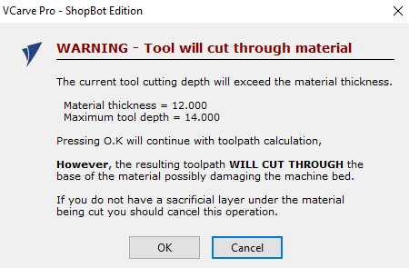
Once we try to finalise our changes before cutting, we will get this warning stating that we will cut past the depth of the material thickness.
Our plywood sheet has a thickness of 12 mm, but we’ve laid it on top of a sacrifice sheet with a larger thickness and set the cutting depth to 14 mm. This is simply to ensure that we are cutting all the way through the plywood, from the top face to the bottom face.
Knowing this, we can safely ignore this warning.
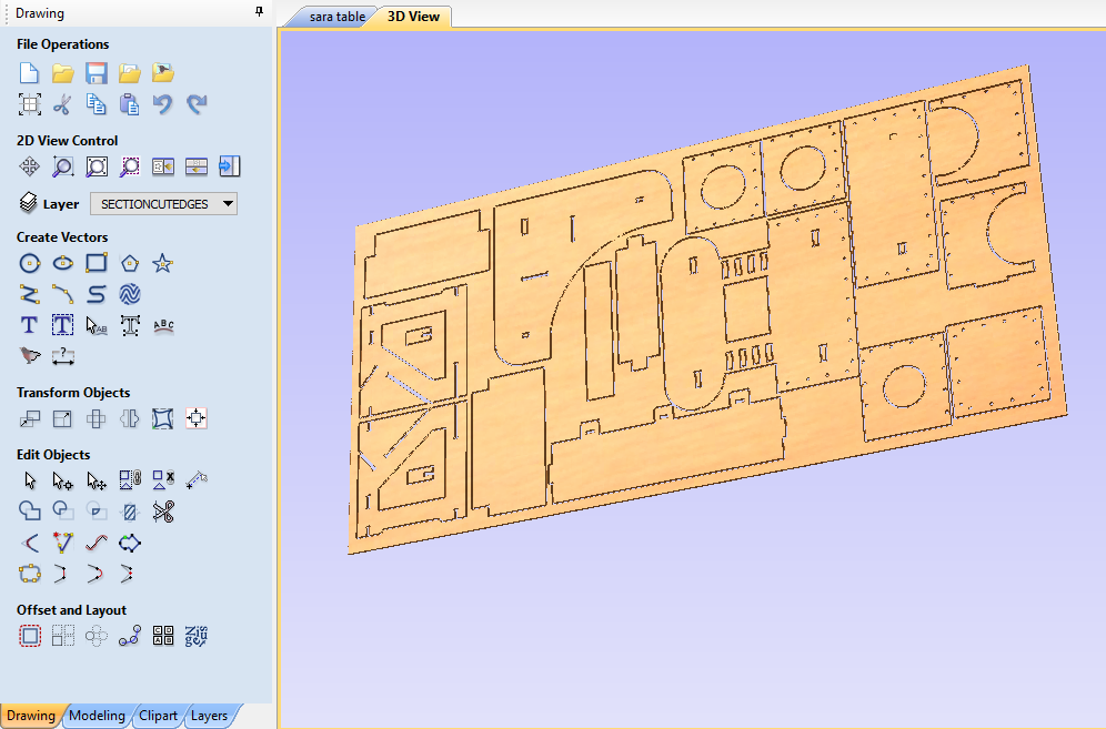
After this, we will be able to view the generated 3D sheet with the toolpath that we’ve set. This is a good time to check if there are any errors or interferences with other pieces that are being cut.
Note
If you zoom in to the left side of the sheet, you can see the other arced fillets I added to the inner slots and joints on the legs!
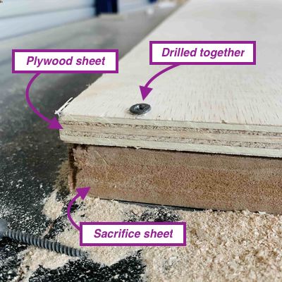
Finally, before cutting, we will load the plywood sheet onto the sacrifice sheet that is secured onto the bed of the CNC machine, then drill it into place on evenly spaced out corners all around the parameter of the sheet to keep it in place.
We will then check that the workplace is clean of debris, and that the end mill drilling bit is securely fastened and not damaged, and also prepare the vacuum for picking up the sawdust.
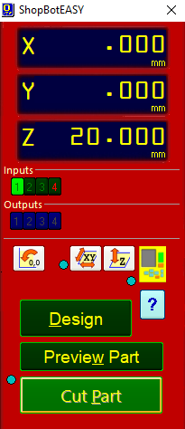
Finally, we can now move the CNC drill bit to the top corner of the plywood sheet, and set that as the origin, with a certain distance away on the Z-axis of 20 mm.
When we are ready to start cutting, we will click on Cut Part.
Warning
Make sure you are following all the guidelines of the Safety Precautions before, during and after operating the CNC machine.
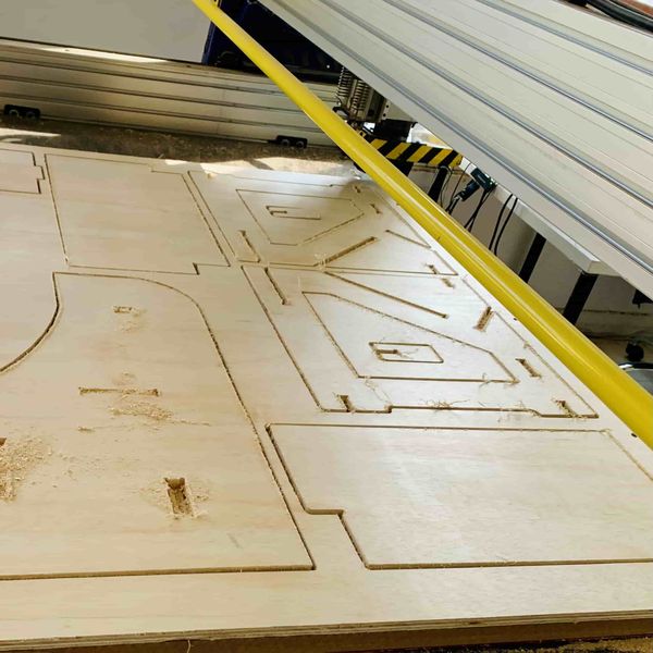
Here is what the sheet looked like after it was completely done cutting out our designs!
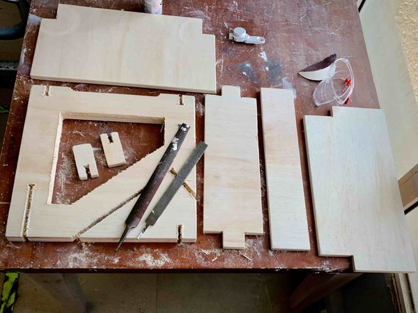
Sanding
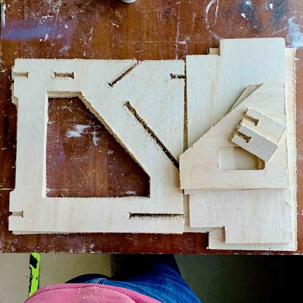
This is what all my pieces looked like after I removed them from the bed of the CNC machine. As you can see, plywood cut with an end mill bit causes a lot of splintering and frayed along the edges. We can smooth these down by sanding down the inner and outer edges.
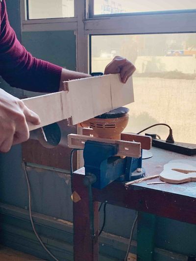
I first start by sanding the outer edges. To do this, I use a mounted rotating sander. I use a low grit of 60 because it is rougher and will sand down the splinters faster.
Once the outer edges are fully sanded down, I used a metal sanding toll to sand down all the inner joints and slots for the parts that need it.
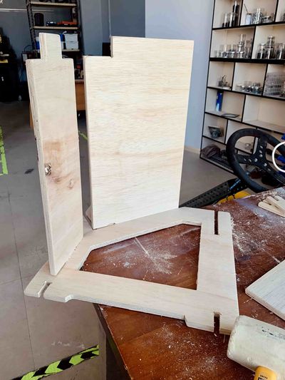
Assembling
Once the sanding is fully complete, I am now ready to assemble my pieces together. To do this, I decided the best way is to attach as many of the pieces to one leg, before attaching the other leg onto it.
I used a mallet to hammer in the pieces, taking care to make sure there are the least amount of splintering and cracks. For the ones I do notice, I will be able to fill in with wood filler later on.
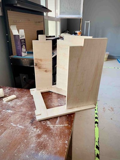
Here you can see that I’ve attaches the front support (on the left) and the sliding shelf (on the right).
Preferably, I would have had this joint much wider than I needed it to be to actually allow it to slide in and out of the joint, but this is probably more secure.
This is after I added the back support (on the right).
After assembling as many parts as possible, I then attached the second leg. To do this, I positioned it on the ground to allow the force of gravity to keep it stable. Once they were connected enough, I turned it upright to have the joints go all the way through.
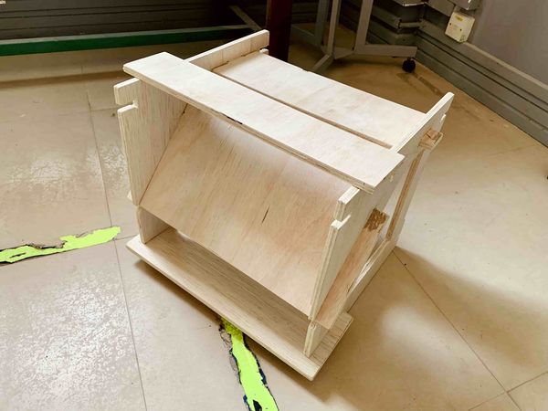
The last pieces left were the support for the sliding shelf, which is the narrow rectangle. This is where the books will be resting on. Then I added the small top supports that would be for the stacking support.
I was not able to cut another bookshelf in order to test out the stacking but I was satisfied with my final product.
Note
One of the stacking tops is missing because it broke while I was hammering it in with the mallet. I cut another piece later on and added it back.