Week 6: Embedded Programming
This week we wrote, tested and executed programs on microcontrollers.
Group Assignment: All About Microcontrollers
To start off the week, we learned about different microcontrollers and their features. I worked with the Adafruit Feather nRF52840 for this week, and gathered a lot of information about its capabilities and useful educational examples on the Adafruit website. This was also helpful for exploring different project ideas by checking out projects using this microcontroller from makers around the world!
Info
What’s the difference between a microcontroller, microprocessor and microcomputer?
Microprocessors are the central unit of any electronic device that controls all internal operations, also known as the Central Processing Unit (CPU).
Both microcontrollers and microcomputers contain a microprocessor to control their functionalities on a lower level. The main difference between them is that a microcontroller is used for specific tasks by controlling inputs and outputs. Whereas a microcomputer is able to do the same at a better capacity, while also running an operating system, and can contain microcontrollers within them.
Raspberry Pi has some of the best collection of microcontrollers and microcomputers that run on the Python programming language.
Reading through the Adafruit Learning System page on the different pinouts on the specific board I’ll be using is greatly helpful for understanding every component on-board and what I can use them for. It also included this handy diagram labelling each of the pinouts to make it easier for us:
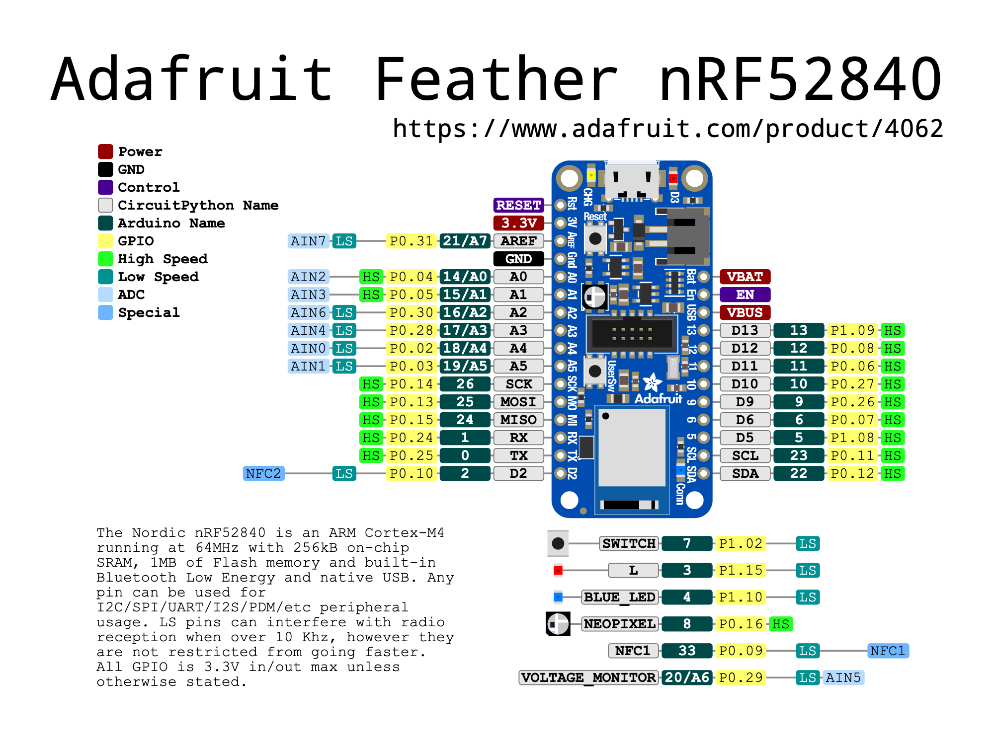
The page also describes everything you need to know to understand what any of these pinouts even mean, but we’ll explore that more later in Week 8: Inputs and Outputs.
Setting Up and Programming on the Microcontroller
First, I connected the microntroller to my laptop using MicroUSB cable. Second, I downloaded two applications that can be used to program the microcontroller in different programming languages: Arduino IDE and Mu Editor.
Arduino IDE
Arduino IDE is an application that uses a subset of the C/C++ programming language and its libraries. They also offer ready-to-use example programs within the application to do different things, such as blinking LEDs, which we will be exploring soon.
Tip
I used Arduino IDE version 1.8 on MacOS, since the newer version 2.0 wasn’t working correctly for me and not recognising the microcontroller. If an application isn’t working as expected on your device, it is better to run an older version because they tend to be more stable.
To set up my microntroller with the Arduino IDE, I followed the Adafruit page describing the steps to take to set up the Board Support Package (BSP) for my Adafruit board. Once this is done, I can now connect the microntroller to my laptop using a MicroUSB cable. Doing this will now show that the CHG orange-colored LED will now start flashing. This indicates that it is now receiving power from its connection to my laptop. I can now reset the microntroller by double-clicking the RESET switch (located between the MicroUSB port and the NeoPixel LED, reference the diagram above to find it), which will make the NeoPixel LED flash to GREEN. If there is any issue with this, it’ll flash RED instead.
Warning
Any time the on-board NeoPixel LED flashes  RED without you intending it to (e.g., if you have code written that controls the NeoPixel LED), it is an indicator that something is wrong.
Either you need to reset the microcontroller again by double-clicking the RESET switch, or there are errors in the code that you’re trying to run on the board. Double-check all these possibilities to troubleshoot the problem.
If none of these options work, try a different MicroUSB cable and/or a different USB port on your device first, then try a different microntroller, because the one you have might not be working.
Next, we will open up the Arduino IDE and navigate to Tools > Board > Adafruit nRF52 > Adafruit Feather nRF52840 Express, then
Tools > Port > /dev/cu.usbmodem14201 (Adafruit Feather nRF52840 Express). You’re now ffully set up to start using Arduino IDE for writing and running code on the microntroller!
Mu Editor
Mu Editor uses the Python prgramming language, and offer easy to follow tutorials with code on their website. This application is a very convenient option for me to use with my microntroller, as you can apply different modes on it, and I can use the Adafruit CircuitPython that is specifically compatible with the Adafruit microntrollers.
To set up my microntroller with the Mu Editor, I followed the Adafruit page describing the steps to take to set up the CircuitPython mode designed for the Adafruit boards. I then followed the next page that shows how to set up the UF2 bootloader to install CircuitPython onto the microntroller.
Tip
As you can see, the Adafruit website has extensive useful documentation for everything you need to do to use their microntrollers. If you have any problems with anything, going back to the documentation to read through and understand everything you need to do can be very helpful!
Additionally, pay attention to the specific OS they mention for any of the steps they describe. I’m running MacOS and only needed the one page I linked to install CircuitPython, but other OSes may require different or additional steps taken, which are all available on the Adafruit website, so read thoroughly!
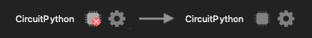
Once you’re done with the steps above, you’ll be ready to immediately use the microntroller by connecting it to your device and opening Mu Editor. You’ll know that the application recognised your microntroller if the following Icon changes from this to the second one:
Note
Note that any code you write and save using Mu Editor will be saved in the CIRCUITPY folder in your computer (shows up as a removable drive).
To be able to run any code, it must be saved as code.py (.py is the extension for Python programs).
To not lose any code you’ve written when you want to run a new program that you need to save as code.py to run, save the current one under a different name (e.g. led_blink.py) and save all your files locally on your device! This last part is important, as if there’s any problems with the microcontroller drive in the future, it might revert back and erase all your files!
Individual Assignment: Blinking LEDs
For this assignment, I wrote code to achieve a specific task in three difficulty levels: easy, medium and hard. I wrote codes for both Arduino IDE and Mu Editor.
Testing by Blinking an LED
I first started out by simply trying out example codes on both applications to simply blink the on-board LED with a set delay. This way I’ll be able to tell that the programs are running as expected, and that the LED is working properly. This is also a good opportunity to start practicing counting the exact duration the LED is on or off by observing it for the next steps.
Note
To display code blocks on Markdown, use this format to start with:
For Arduino code = ```c
For Python code = ```py
Start a new line, paste your code, then start another new line and end with ```
This was my code on Arduino IDE that I got by navigating to File > Examples > 01.Basics > Blink:
// the setup function runs once when you press reset or power the board
void setup() {
  // initialize digital pin LED_BUILTIN as an output.
  pinMode(LED_BUILTIN, OUTPUT);
}

// the loop function runs over and over again forever
void loop() {
  digitalWrite(LED_BUILTIN, HIGH);   // turn the LED on (HIGH is the voltage level)
  delay(1000);                       // wait for a second
  digitalWrite(LED_BUILTIN, LOW);    // turn the LED off by making the voltage LOW
  delay(1000);                       // wait for a second
}
This was my code on Mu Editor that I got from Adafruit but changed the delay to 1 second to get the same result as the Arduino code and added comments for clarity:
# import python libraries to use their functions
import time         # controls delay, aka 'sleep'
import board
import digitalio    # control microntroller input & output

led = digitalio.DigitalInOut(board.LED)      # controls the D3 LED
led.direction = digitalio.Direction.OUTPUT   # set LED as output

while True:                # equivalent to loop() in the Arduino code
    led.value = True       # True = LED on
    time.sleep(1)          # delay/wait for 1 second
    led.value = False      # False = LED off
    time.sleep(1)          # delay/wait for 1 second
Tip
Understanding and writing programming languages can be difficult if you have no background around it. Oftentimes, you can find code online for the exact thing you want to do with your microcontroller. Searching for them and reading the descriptions and especially the comments that describe what each line of code does will slowly build an understanding of how they work so you can edit them for your project needs!
Also, you can copy the test or download my code files for any of these by clicking on the code links I included!
To run the code on our microcontroller follow the following steps:
* For Arduino IDE:
* Click on the  Verify icon to check that your code is all correct. You’ll know it’s all good if it can finish compiling.
* Click on the
Verify icon to check that your code is all correct. You’ll know it’s all good if it can finish compiling.
* Click on the  Upload icon to download the code to your microcontroller. It will start running as soon as this is complete.
* To run new code or in case you’re having an issues uploading your code, you have to
Upload icon to download the code to your microcontroller. It will start running as soon as this is complete.
* To run new code or in case you’re having an issues uploading your code, you have to RESET your microcontroller.
- For Mu Editor:
- Click on the
 Check icon to check that your code is all correct. You’ll know it’s all good if it says so on the bottom of the screen. If there are issues, it’ll show you what lines of code are the problem and what the issue with them is.
 - To upload and run your code, you just need to save the file as
code.py. - You never need to reset your microntroller using Mu Editor unless it is not recognising it.
Here we can see a video showing that the LED on the microntroller is blinking, showing an orange light, with a delay of 1 second:
Easy Mode Challenge
The easy mode challenge was to blink the on-board LED on the microntroller with delay periods that are randomised between 1-5 seconds.
This was my code on Arduino IDE:
// the setup function runs once when you press reset or power the board
void setup() {
  // initialize digital pin LED_BUILTIN as an output.
  pinMode(LED_BUILTIN, OUTPUT);
}

// the loop function runs over and over again forever
void loop() {
  digitalWrite(LED_BUILTIN, HIGH);   // turn the LED on (HIGH is the voltage level)
  delay(random(1000, 5000));         // wait for any 1-5 seconds
  digitalWrite(LED_BUILTIN, LOW);    // turn the LED off by making the voltage LOW
  delay(random(1000, 5000));         // wait for any 1-5 seconds
}
This was my code on Mu Editor:
import board
import digitalio
import time
import random  # to use function to generate random numbers

# use LED as output
led = digitalio.DigitalInOut(board.LED)
led.direction = digitalio.Direction.OUTPUT

while True:
    led.value = True  # LED on
    time.sleep(random.randint(1, 5))  # picks random delay from 1-5 seconds
    led.value = False                 # LED off
    time.sleep(random.randint(1, 5))
Here we can see a video showing that the LED on the microntroller is blinking and due to the delay, is on or off at anywhere between 1 to 5 seconds:
Medium Mode Challenge
The medium mode challenge was to pre-code the microntroller to blink the LED in a pattern replicating one word in morse code.
Here is a table of the rules we are using for how the LED should act for each element needed to replicate morse code:
| Morse Code | LED Action |
|---|---|
| Dot | 1 second light ON |
| Dash | 2 seconds light ON |
| Gap between dots and dashes | 0.5 seconds light OFF |
| Gap between letters | 3 seconds light OFF |
| Gap at the end of a full word | 5 seconds light OFF |
Here is a table of what all the letters in the alphabet are in morse code:
| A | B | C | D | E | F |
|---|---|---|---|---|---|
| .- | -… | -.-. | -.. | . | ..-. |
| G | H | H | I | J | K |
| –. | .... | .... | .. | .— | -.- |
| L | M | N | O | P | Q |
| .-.. | – | -. | — | .–. | –.- |
| R | S | T | U | V | W |
| .-. | … | - | ..- | …- | .– |
| X | Y | Z | |||
| -..- | -.– | –.. |
This was my code on Arduino IDE:
// the setup function runs once when you press reset or power the board
void setup() {
  // initialize digital pin LED_BUILTIN as an output.
  pinMode(LED_BUILTIN, OUTPUT);
}

// dot function - 1 sec ON
void dot() {
  digitalWrite(LED_BUILTIN, HIGH);
  delay(1000);                        // ON for 1 sec
  digitalWrite(LED_BUILTIN, LOW);
  delay(500);                         // OFF for 0.5 sec
}

// dash function - 2 sec ON
void dash() {
  digitalWrite(LED_BUILTIN, HIGH);
  delay(2000);                        // ON for 2 sec
  digitalWrite(LED_BUILTIN, LOW);
  delay(500);                         // OFF for 0.5 sec
}

// the loop function runs over and over again forever
void loop() {
  // spells out SARAH

  // S = ...
  for(int i = 0; i < 3; i++) {   // for loop, repeats dot() 3 times
    dot();
  }
  delay(3000);                   // 3 sec delay between letters

  // A = .-
  dot();
  dash();
  delay(3000);                   // 3 sec delay between letters

  // R = .-.
  dot();
  dash();
  dot();
  delay(3000);                   // 3 sec delay between letters

  // A = .-
  dot();
  dash();
  delay(3000);                   // 3 sec delay between letters

  // H = ....
  for(int i = 0; i < 4; i++) {   // for loop, repeats dot() 4 times
    dot();
  }
  delay(5000);                   // 5 sec delay at end of word

}
This was my code on Mu Editor:
import board
import digitalio
import time

# use LED as output
led = digitalio.DigitalInOut(board.LED)
led.direction = digitalio.Direction.OUTPUT

# function for dot
def dot():
    led.value = True  # LED on
    time.sleep(1)  # on for 1 second
    led.value = False  # LED off
    time.sleep(0.5)  # off for 0.5 seconds

# function for dash
def dash():
    led.value = True  # LED on
    time.sleep(2)  # on for 2 seconds
    led.value = False  # LED off
    time.sleep(0.5)  # off for 0.5 seconds

# gap at end of letter of a word
def letter_end():
    time.sleep(3)

# gap at end of a word
def word_end():
    time.sleep(5)

while True:
    # manually spell out word - SARAH
    # S = ...
    for index in range(3):    # for loop equivalent, repeats 3 times
        dot()                 # calling dot function
    letter_end()              # calling function for gap between letters

    # A = .-
    dot()
    dash()                    # calling dash function
    letter_end()

    # R = .-.
    dot()
    dash()
    dot()
    letter_end()

    # A = .-
    dot()
    dash()
    letter_end()

    # H = ....
    for index in range(4):
        dot()
    word_end()               # calling function for gap at end of word
Here we can see a video showing that the LED on the microntroller is blinking and if we reference the table above to read each letter, it spells out SARAH:
Hard Mode Challenge
The hard mode challenge was to use the serial monitor to enter user input for what the LED blinking delay should be.
Info
What is a serial monitor?
The serial monitor is an interactive monitor that allows a user to enter inputs to influence the code execution.
This was my code on Arduino IDE:
#include "Adafruit_TinyUSB.h"
int num;
void setup() {
  pinMode(LED_BUILTIN, OUTPUT);
  Serial.begin(9600);
}

void loop() {
  Serial.println("Enter LED delay number in seconds: ");
  while (Serial.available() == 0) {}
  num = Serial.parseInt();
  digitalWrite(LED_BUILTIN, HIGH);
  delay(num*1000);
  digitalWrite(LED_BUILTIN, LOW);
  delay(num*1000);
}
To use the serial monitor in Arduino IDE, navigate to Tools > Serial Monitor.
Warning
My Arduino code for this challenge did not work because I couldn’t get the serial monitor working correctly.
This was my code on Mu Editor:
import board
import digitalio
import time

# use LED as output
led = digitalio.DigitalInOut(board.LED)
led.direction = digitalio.Direction.OUTPUT

while True:
    num = int(input("Enter delay number: "))  # user input as integer number
    if num <= 0:
        print("Incorrect input. Try again.")  # negative time doesn't exist (i think...?)
        continue  # restarts the loop so you can enter a different number
    led.value = True
    time.sleep(num)
    led.value = False
    time.sleep(num)
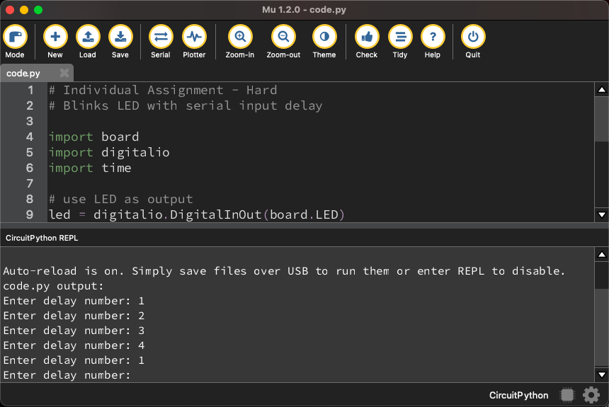
To use the serial monitor in Mu Editor, click on the Serial icon, then your code and enter values when the Enter delay number: prompt shows up.
Here, I wrote the delay number in seconds every time it prompted me to, which happens when it is done blinking the LED with my delay input:
Here we can see a video showing the LED replicating the delays that I wrote in the serial monitor: