Week 3: Computer-Controlled Cutting
This week we learned the fundemental basics of operating a laser cutting machine and used the 2D and 3D softwares we explored the week before to design and then cut our own final products using the machine. We also learned how to use a vinyl cutting machine and how to create two different products using it.
Laser-Cutting
Facts About the Machine
The laser-cutting machine available in our lab is a CO2 laser. It’s specifications are that it has a power of 100 Watts, and the size of the bed is 90 x 60 cm, making it the maximum size of what can be cut out of it. The machine operates in three axes, the X, Y and Z-axis.
You can cut or engrave different materials with the machine with varying thickness, such as wood, cardboard, acrylic and medium-density fibreboard (MDF), which is a material made by combining wood residuals with wax and resin.
Safety Precautions
The main safety measures and precautions that are needed to be taken when operating the laser-cutting machine focus on the prevention and resolving in case of a fire. The main causes of a sustaining fire is oxygen, flammable material and a spark. When the machine is running, it has a vacuum that provides airflow that introduces oxygen. To combat this, we must first start by making sure that the machine is completely switched off, both from its controls, as well as through the outlet that is providing power to it. Second, we should take steps to extinguish the fire, by either using a CO2 fire extinguisher (which is a blue-colored canister found in the lab), and/or using the fire blanket to suffocate the flame and remove oxygen and airflow from the equation. Take care to not use the water fire extinguisher (which is a red-colored canister also found in the lab), as to not cause water damage to the machine. The final precaution is to always have the door securely and completely shut before operating the laser, and standing a good distance away from it while it works to avoid bodily harm. Another personal health precaution is to wash your hands after handling laser-cut material, as the burnt remnants of the cutting procedure are dangerous if inhaled or ingested.
Warning
Some materials should NOT be used with the laser-cutting machine, as it damages the laser or emitts dangerous gas into the atmosphere that are harmful if inhaled. These materials include: PVC (e.g., vinyl and artifical leather), polycarbonate that is thicker than 1 mm, plastics such as ABS and HDPE (there are other safer plastics that can be found here), PolyStyrene and PolyPropylene foams, fibreglass and coated carbon fiber.
Group Assignment 1: Laser Focus Exercise
The purpose of this exercise is to determine the focal point needed to set for the laser to cut the required material with precision and accuracy and minimal waste or damage to the material.
To start, we launched RDWorks, which is a laser-cutting and engraving operations software that we can use to create design files or open up design files that we worked on in other softwares, such as Fusion 360 and Inkscape.
Info
It is important to note that laser-cutters cut out 2D designs on material, so we will be uploading DXF files to the machine.
To do this on Fusion 360, you must right-click on the sketch of your design and click Export as DXF. If you want to include multiple sketches, you can use Project to include all selected sketches in your DXF file. You can then preview these locally on Inkscape before opening it up on RDWorks to ensure the design has been exported correctly. Otherwise, you can further edit it on Inkscape as needed.
We start this experiment by cutting out a 20 x 4 cm sheet of 6 mm acrylic using the laser-cutting machine. We then position the acrylic piece on a cube, so that it is sloped like a ramp. We positioned the laser to just barely be touching the highest point of the acrylic ramp before we start cutting.
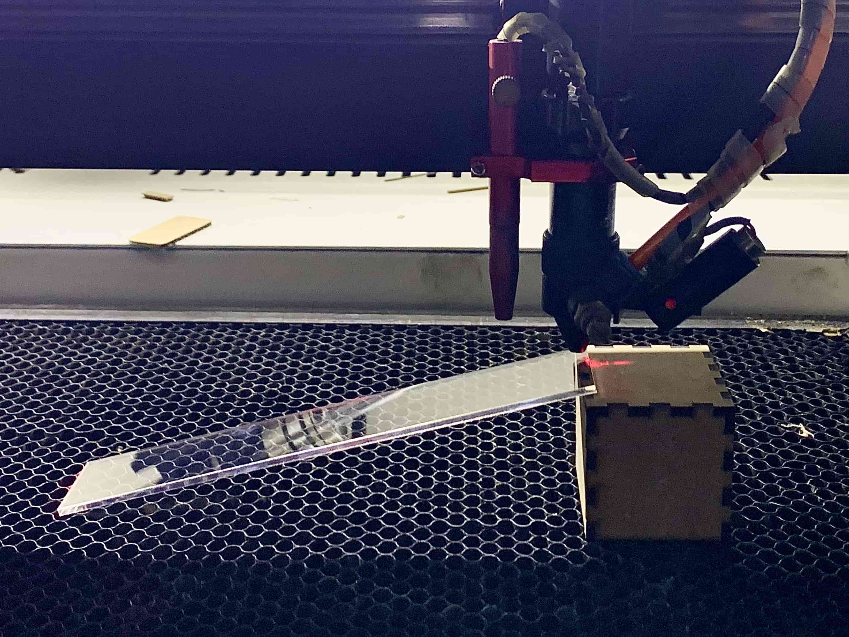
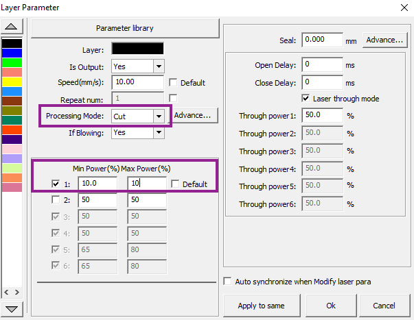
We then operated the laser-cutting machine to cut a straight line down the acrylic ramp. We did this by drawing a line on RDWorks, as shown below, and setting the power and speed (more on that in the next section).
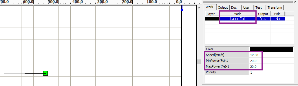
Info
Notice the mode is labelled as Cut. This is to completely cut through the material. Alternatively, we can also engrave the material using the Scan mode.
Upon examination, the line created shows variations throughout. We can notice upon inspection that the line starts out thin and precise, then gets gradually much wider and imprecise, before it thins out again into its thinnest point at the end.
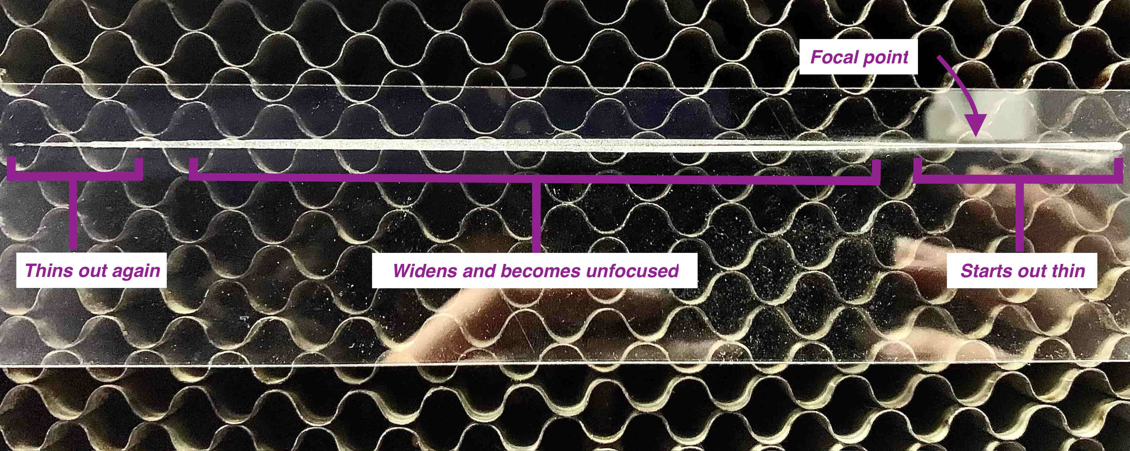
From this result, we can deduce that the finest, thinnest cuts that are made are the most precise, in which the laser is at a distance away from the material where it can make focused cuts. Alternatively, the thickest, widest cuts are the most imprecise, and can be described as the distance where the laser is unfocused and cannot cut the material properly, because it is either too close or too far away from the material. This experiment can be used to determine the focal point where it is best for the laser to be at a specific distance on the Z-axis to precisely and accurately cut the material in, which varies depending on the type and thickness of the material used.
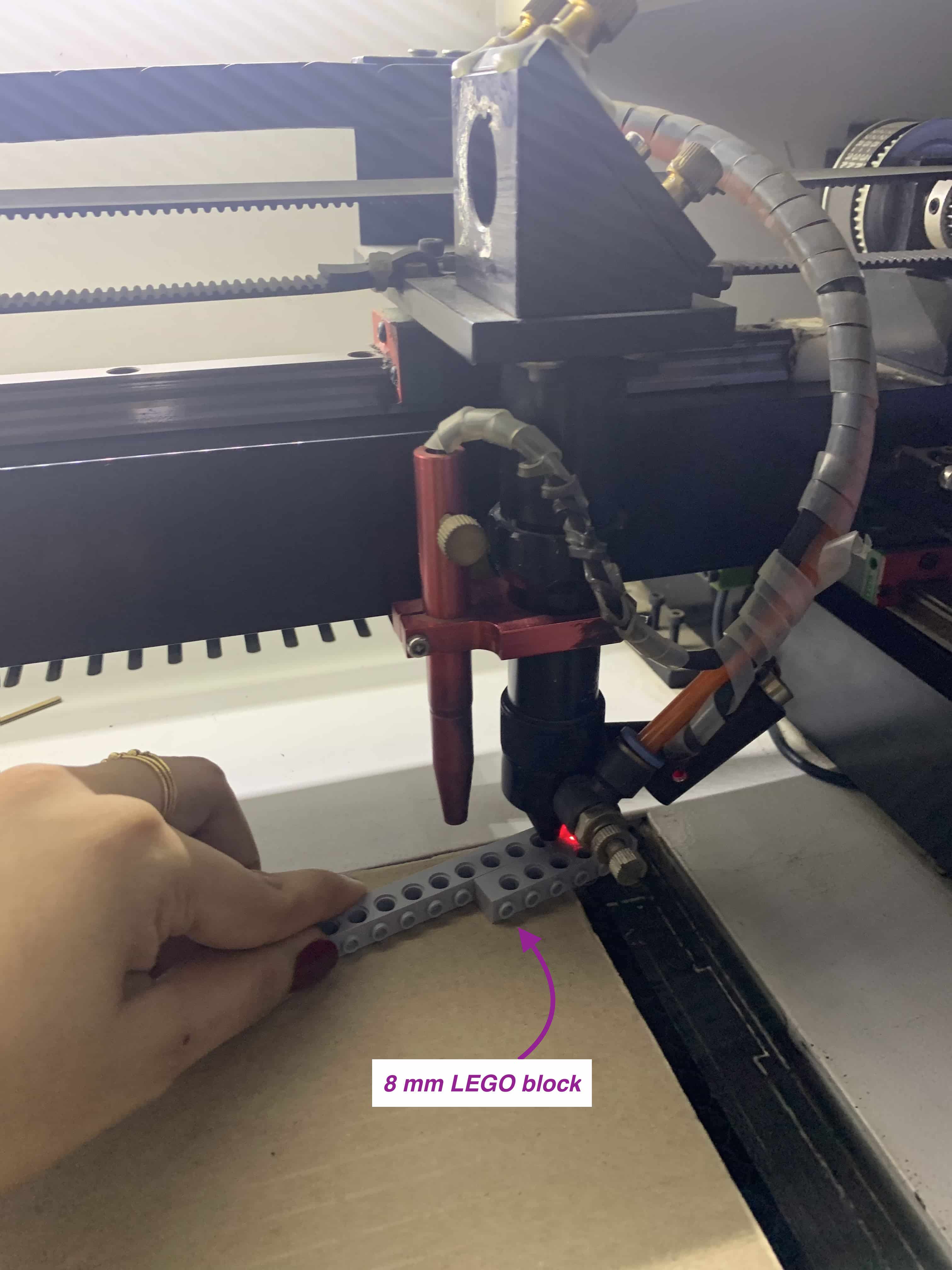
For us to determine the focal point, we found the point where the laser cut the acrylic piece the most precisely (where the line is thinnest) and used a ruler to measure the distance between the tip of the laser head and the point on the acrylic piece. To calculate our expected focal point, we measured the distance from the seam above the air intake to the material surface (as illustrated in the image below), which was found to be 4.8 cm. By subtracting that from the distance in between, we found that the expected focal point was around 0.8 cm or 8 mm. Using this information, we used an 8 mm wide object in the form of a LEGO block to calibrate the focal point during setup for future use of the laser-cutting machine.
Info
Why does the focal point matter?
The focal point is important to determine to cut out precise designs with pre-determined dimensions, which is important for press-fit designs that need to be able to fit together. When operating a laser-cutting machine that will follow the dimensions specified in the design files, it will cut out the sizes that are provided, but will always have some room for error where the actual dimensions will be smaller from the edges that will be burned by the laser and damaged.
By operating the laser at its focal point for that specific material, we reduce the amount of material wasted, and also have a better chance at cutting out the design closer to the desired dimensions.
It also helps us to know what measurement of error to account for, so that we can adjust our dimensions to account for the waste and cut out a design that will fit our desired dimensions more precisely.
Group Assignment 2: Characterizing Focus, Power, Speed, Rate, Kerf and Joint Clearance
Speed and Power
For this experiment, our objective was to determine the ideal speed and power settings for cutting designs with the laser-cutting machine.
Info
What do speed and power actually represent?
Speed (measured in mm/s) is how quickly or slowly the laser nozzle will move around in the X and Y directions. Higher speed means that it will laser-cut the design faster and avoids the likelihood of igniting a fire, which is important for materials like cardboard. However, a material like acrylic is harder to cut through and requires a slower speed to fully cut through the material, especially if it is thicker.
Power (measured in Watts) is how powerful the laser is when firing. Higher power means that it’ll be able to cut through more easily, and is required for cutting through thicker material and material that is harder to cut through, such as acrylic. Lower power means that the laser beam will be weaker, but this is not an issue if we only laser-cut at the minimum power needed, as higher powers can ignite fires as well.
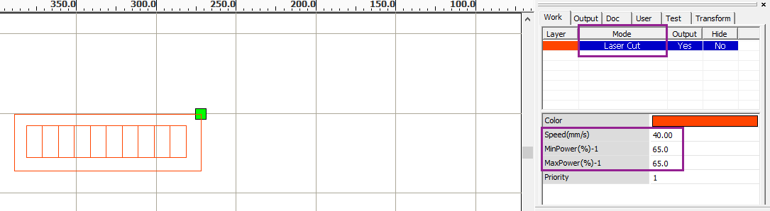
In RDWorks, we created a grid of 2 x 4 squares of 4 mm dimensions. We then color-coded each box to individually select their own power and speed settings for our experiment. We started from a speed of 10 mm/s for the first square, and incremented by 10 for each following square. For the power, we started with 50 Watts and incremented by 5 for each following square.
This is what the final design looked like on RDWorks before we started laser-cutting.
We then downloaded the file of our square grids to the laser-cutting machine, set down a piece of 6 mm cardboard, and then proceeded to calibrate the laser. To do this, we first moved the laser around the axis of the bed using the arrow buttons to the position we wanted it to start cutting at.
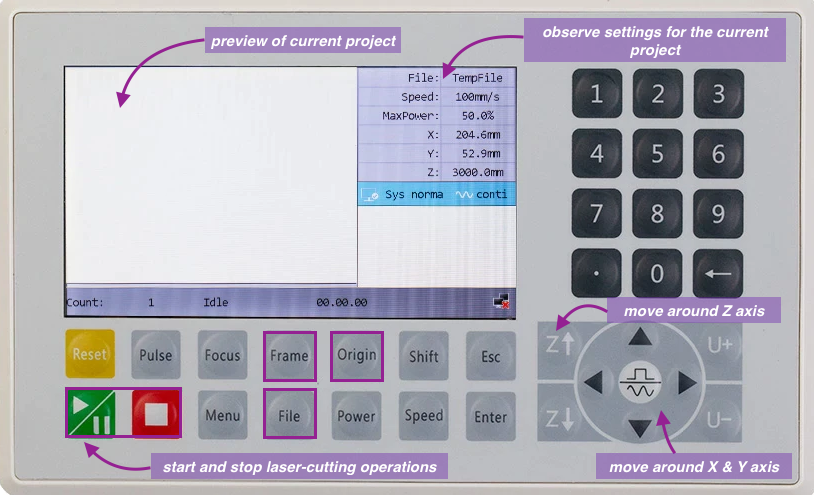
Once it was in the correct position on the X and Y axis of the bed, we then calibrated the Z axis position with Z arrow buttons using the information we learned in the focal point experiment. We used the 8 mm LEGO brick to help determine how far to lower or raise the laser using the buttons, as shown in the image in the previous section.
Once we were satisfied with the positioning of the laser, we clicked Origin to set it as the starting point that the laser will cut from. We then clicked Frame to have the laser arm preview the overall area it was going to cut, using our design’s dimensions as a guide. We will also select our design file that we download by clicking on the File and navigating to ours. When we were finally ready to start, we clicked the Start button and the machine began cutting out the designs.
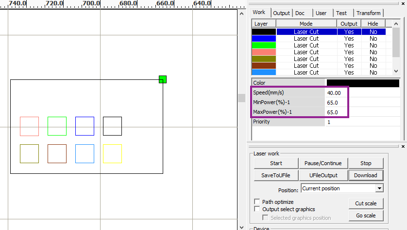
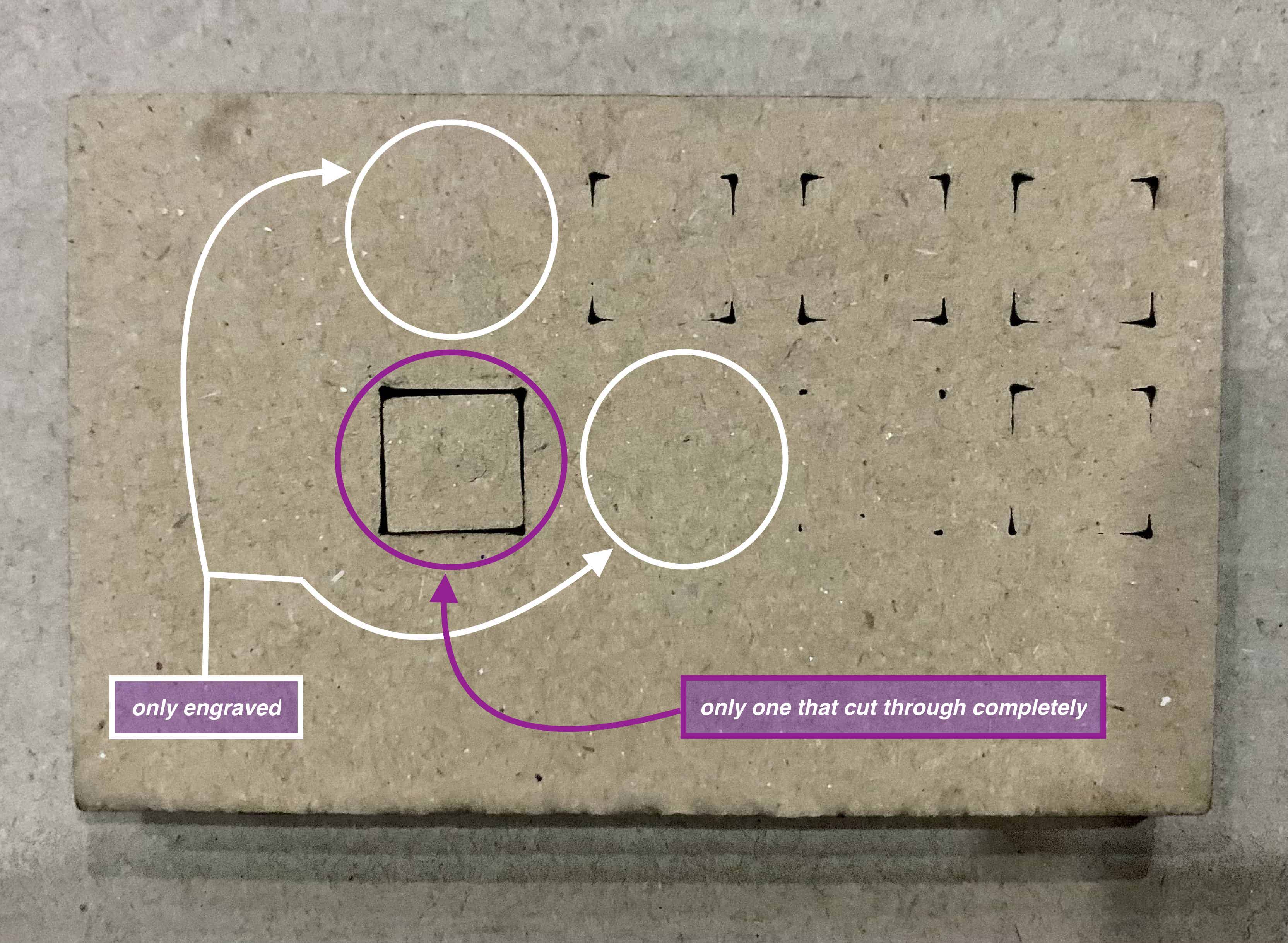
The result of our experiment showed that only one of the squares was cut completely through on both sides of the cardboard, which had the settings as a Power of 65 Watts and Speed of 40 mm/s.
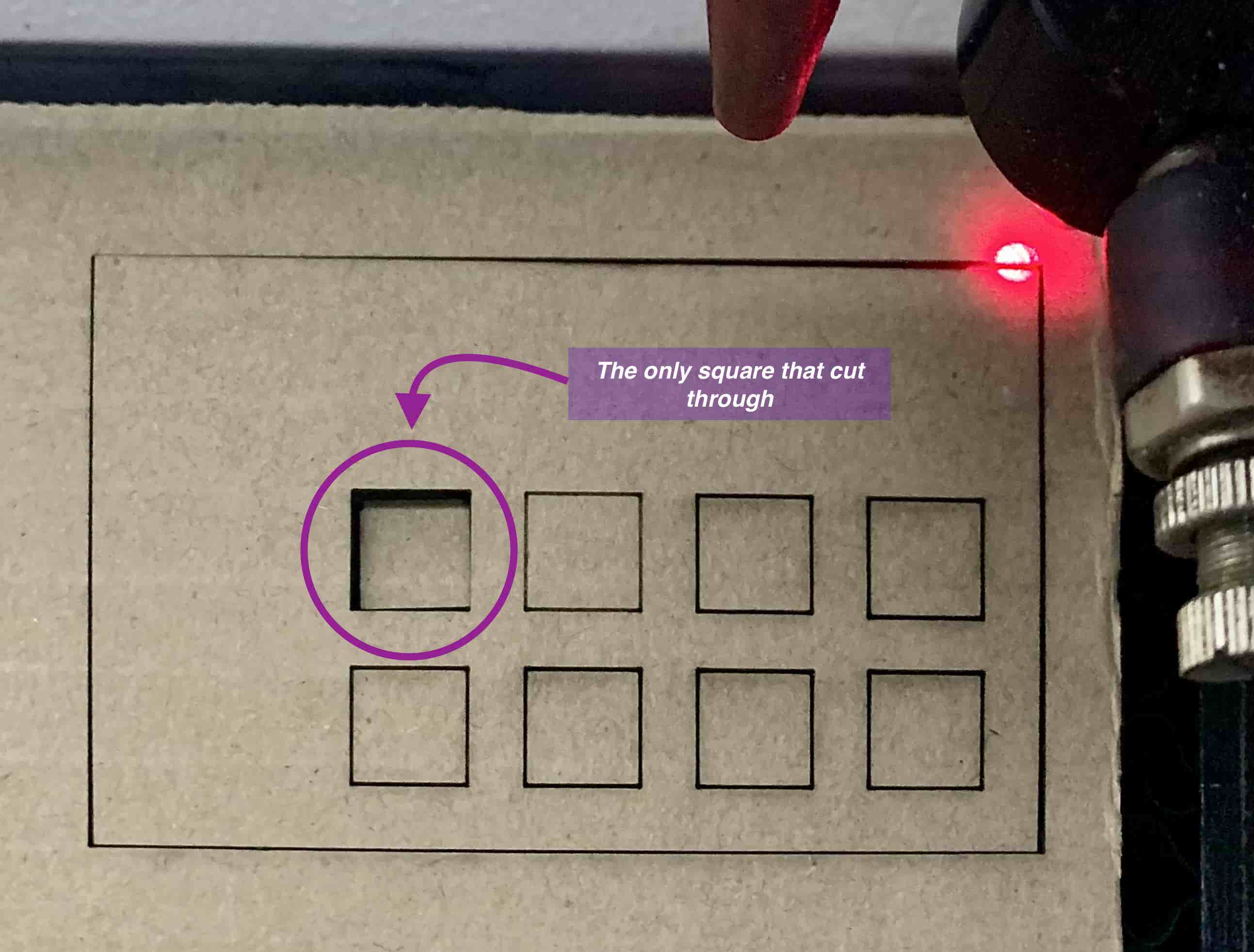
Observing the back of the carboard, we can see the other grids were only cut through at the corners, or were only engraved into the cardboard and so did not cut through it at all.
Kerf
Info
What is Kerf?
Kerf is the width of a cut made by the laser. It is the result of material removal during the cutting process.
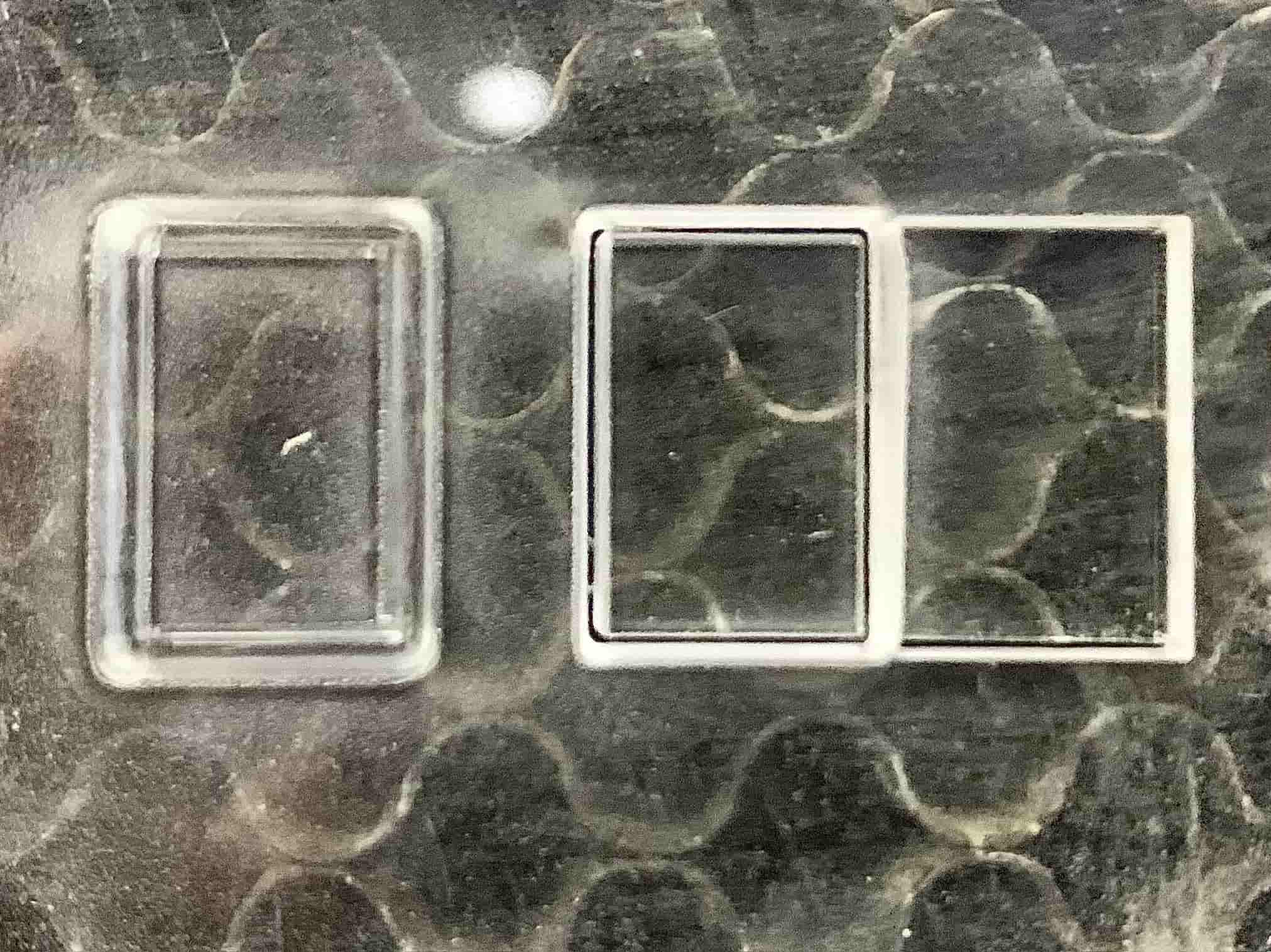
You can see in the photo below an example of variation in kerf on acrylic. The box with the widest kerf or outline width on the left side is the result of the laser not cutting at the focal point and by improper power and speed settings.
Kerf affects the amount of waste left from cutting material. We want to minimise the amount of waste to cut efficiently and have the best outcome of our design where the cuts are fine and precise.
To experiment with the best settings for kerf, we designed a 2D rectangle encapsulating smaller boxes that are all next to one another, shown as multiple lines running parallel to the shortest edge. We set how the laser cutting machine would cut them and downloading it and started cutting. The design on RDWorks is shown below.
After the cutting was done, the result was as shown below. It can be observed that each of the boxes do not completely fit in the inner rectangle space. This is due to the varying kerf that cut around each square and how much material was wasted cutting around them.
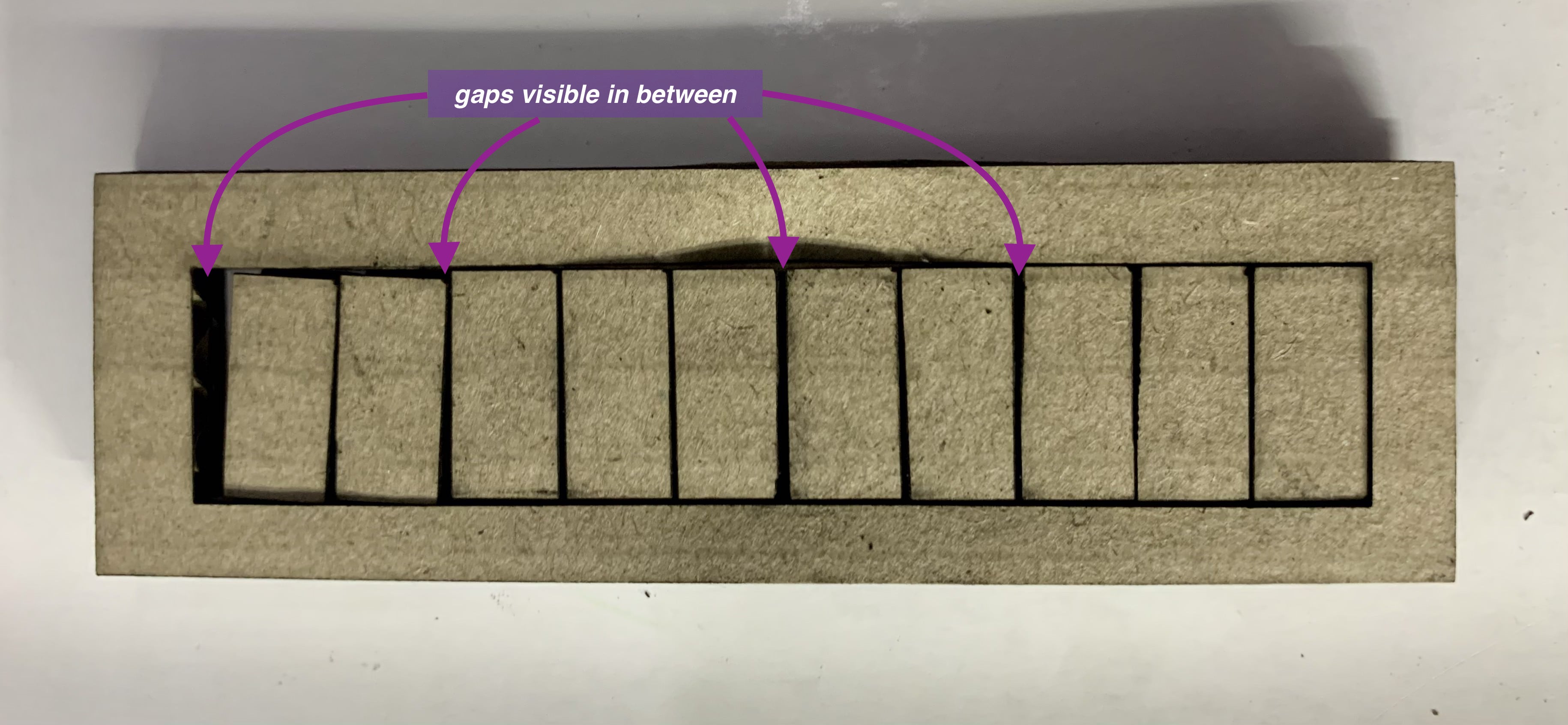
To analyse the kerf resulting from the cuts, we measured the width of each of the squares, as well as the inner seam of the encapsulating rectangle to compare it to the original dimensions we set the design to so we can then analyse how much allowance should be given to ensure that the laser-cut pieces will be in more of the same dimensions that we originally intended for.
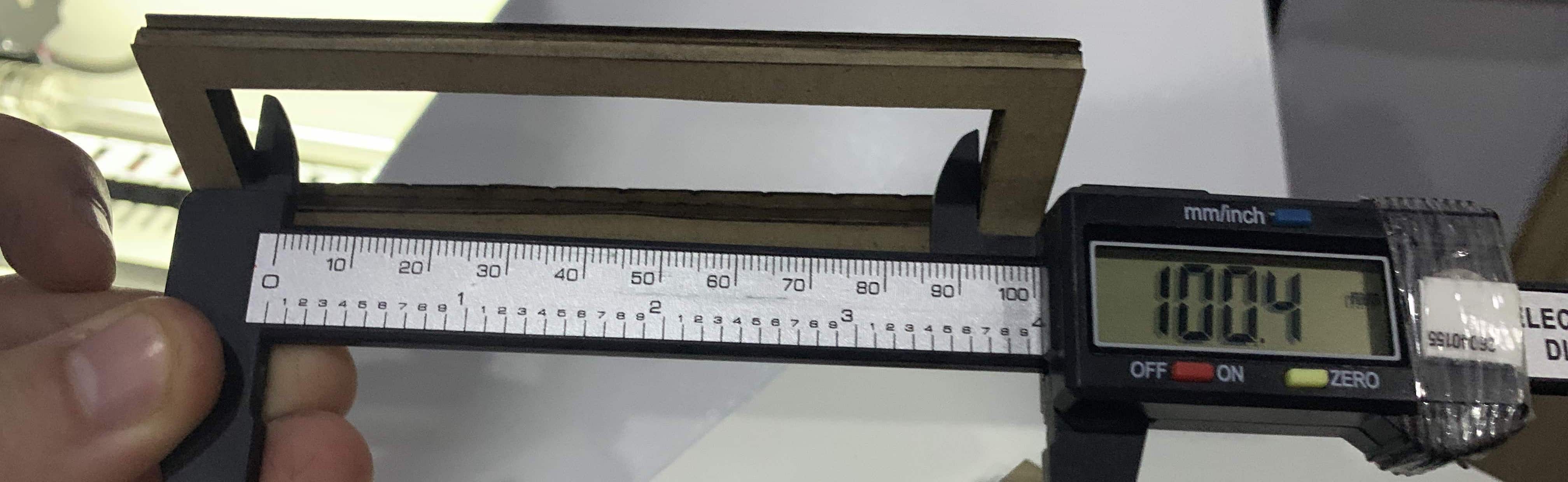
Measuring the rectangle lengthwise:
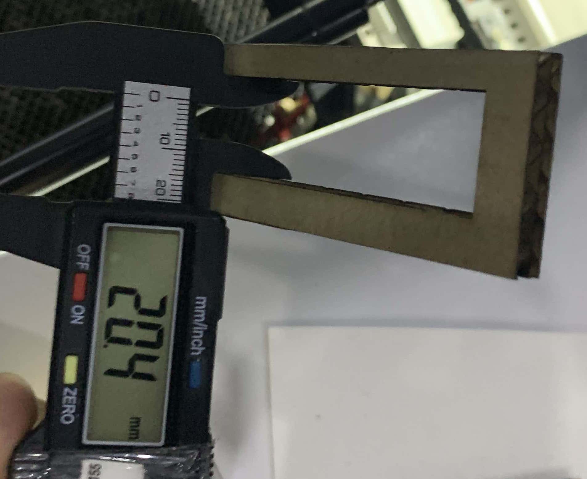
Measuring the rectangle widthwise:
Measuring the thickness of the parallel small rectangles:
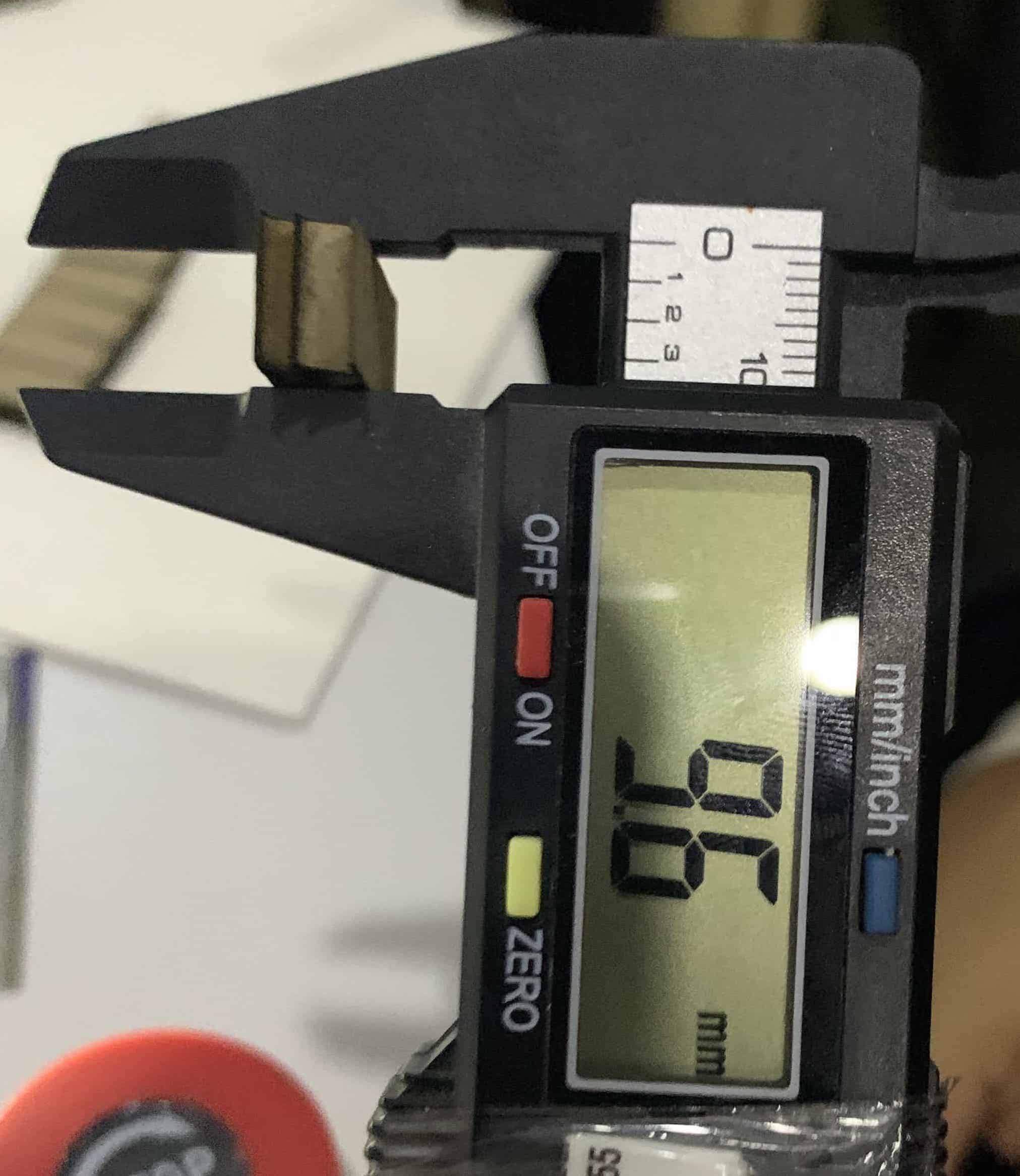
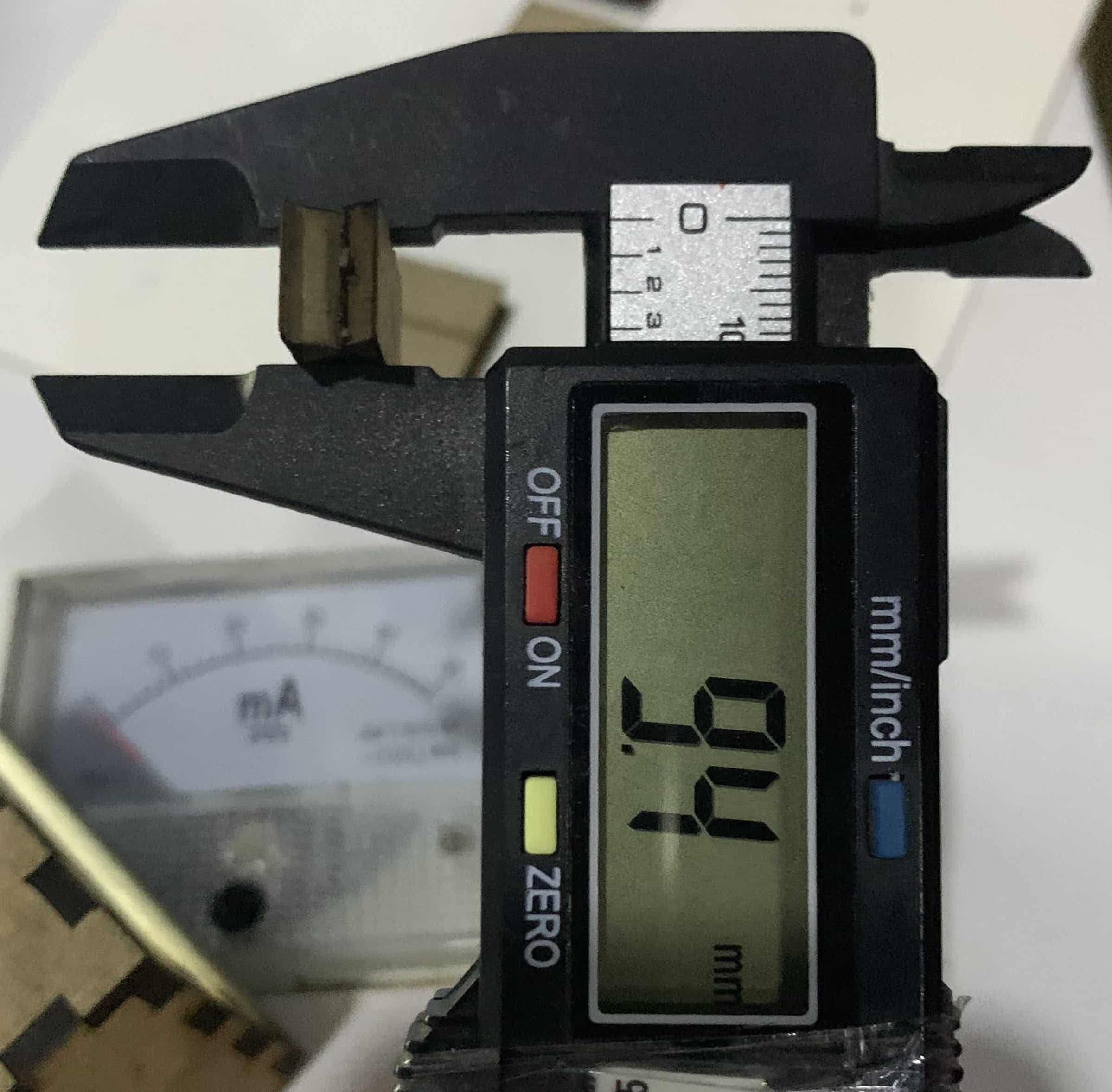
We found that for most of the prallel small rectangles pieces, the kerf was at an average of about 0.2 mm. Which means that in our designs, we can probably increase the dimension by that amount so that it will be the original dimension that we need after cutting.
Joint Clearance
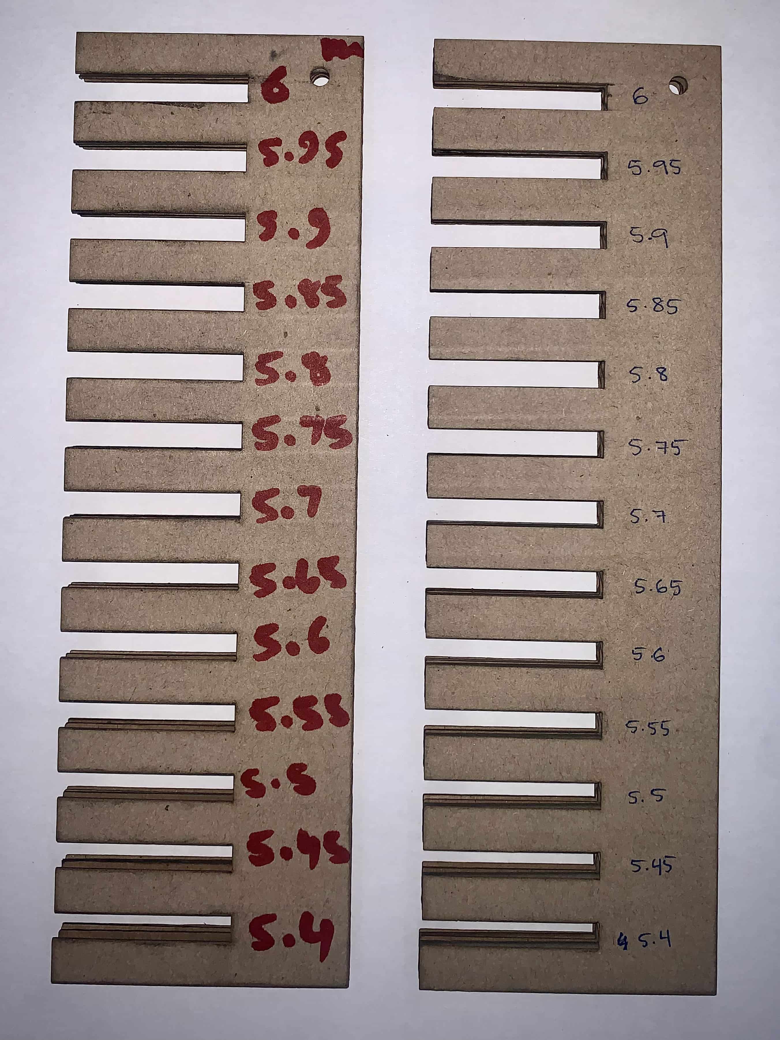
Finally, we created a design as a rectangle with parallel joints spaced out from each other along the longest edge, each had a specific set thickness from 5.4 mm to 6 mm. We laser-cut two duplicates of this design and labelled each joint by its corresponding thickness, as shown below.
Info
It is important to test for joint clearance with the information we learned from kerfing before designing our press-fit prototypes in order to know what best thickness we can set the joints of our designs to for a parametric design. This way, we can know if the joints of our design can fit together without restricting the material or ruining it.
In order to test the joint clearance of different thicknesses, we take each of the laser-cut pieces and fit each joint together with its matching thickness. What we are looking for is to ensure the fit is secure, not too loose, but also that it is not too tight or requires too much physical force to fit together, as this can ruin the materal. From our experiment of trying each of them, we found that the best fit was a thickness of 5.6 mm, which accounting for the information we gathered from the Kerf experiment, we need to add 0.2 mm to account for waste, which means that we should set our parametric press-fit design prototypes to a thickness of 5.8 mm.
Individual Assignment: Press-Fit Design
Designing on Fusion 360
Info
What is Parametric Design?
A design is parametric when you have parameters of your design that are globally set by the software you’re using. The benefit of designing with addressable parameters is so you can change them easily, since it will automatically update the whole design in every instance that you used a defined parameter.
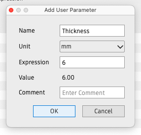
To make our press-fit design parametric, we will start by defining a user parameter for Thickness in Fusion 360. This is because, as we learned from our group assignment experiments, the thickness may vary based on the thickness of the material being used (in this case, the material is cardboard), as well as the extra amount that the laser will cut outside of the thickness we digitally set for our design.
To do this, go to Modify > Change Parameters and click + User Parameter then set the name and dimension in mm:
I set the thickness to 6 mm to start with since it is the thickness of the cardboard I will cut out my press-fit design in, but this value can be changed at any time.
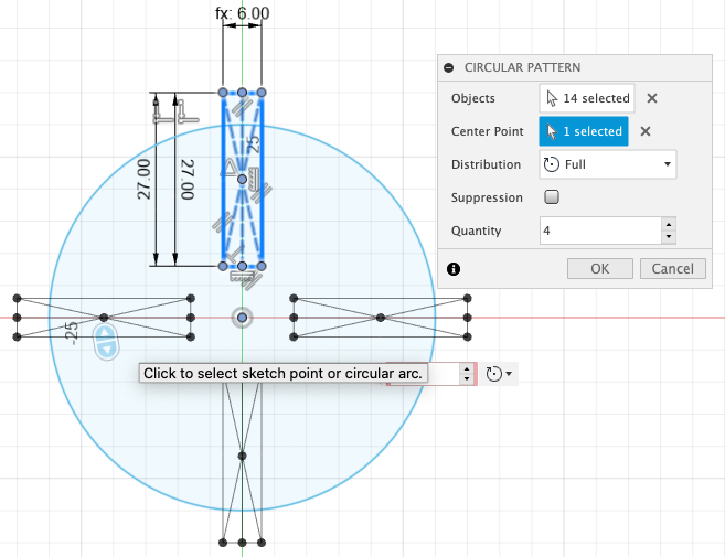
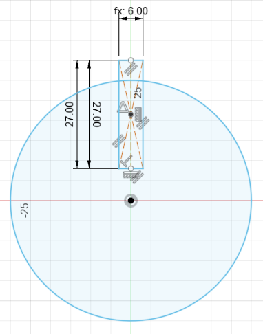
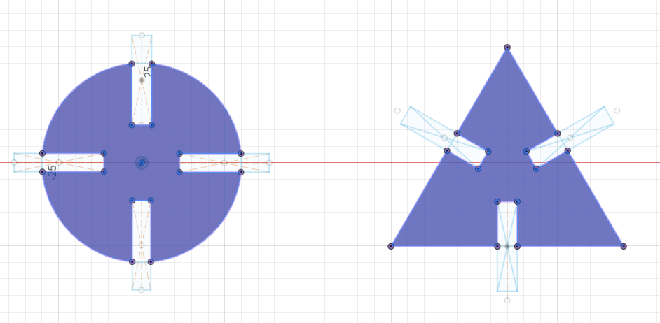
I start off by making a simple circle design with joints. To do the joints, I enter the Thickness parameter to define the dimension of the width of the rectangle. This rectangle will act as our first joint.
Next, I use circular pattern to duplicate the rectangles that will be our joints that we fit together.
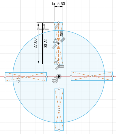
Next, I will change the thickness parameter to be 5.6 mm to account for joint clearance. This is the benefit of having a parameter design, since it updated my sketch automatically.
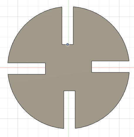
Finally, after extruding to 6 mm for the thickness of the cardboard, we can see the shape of the first press-fit that I will be using.
I repeated the same steps for this design for a triangle shape, which appeared as follows:
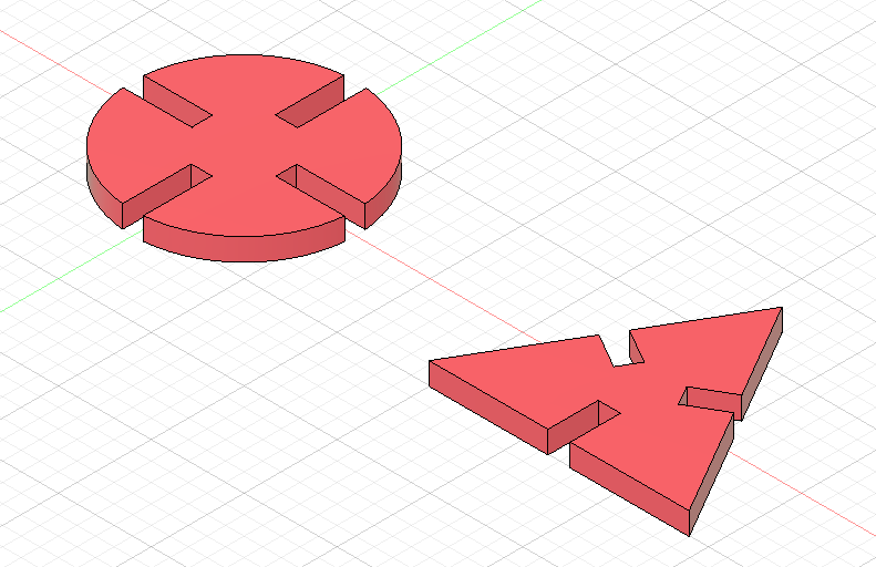
Here is the completed design:
To move our designs over to RDWorks for laser-cutting, we will have to save our files as DXF. Since we have multiple designs, to include all of them, we can enter the sketching mode and first use Project then right-click the sketch and click Save as DXF:
Cutting Designs Out on the Laser-Cutting Machine
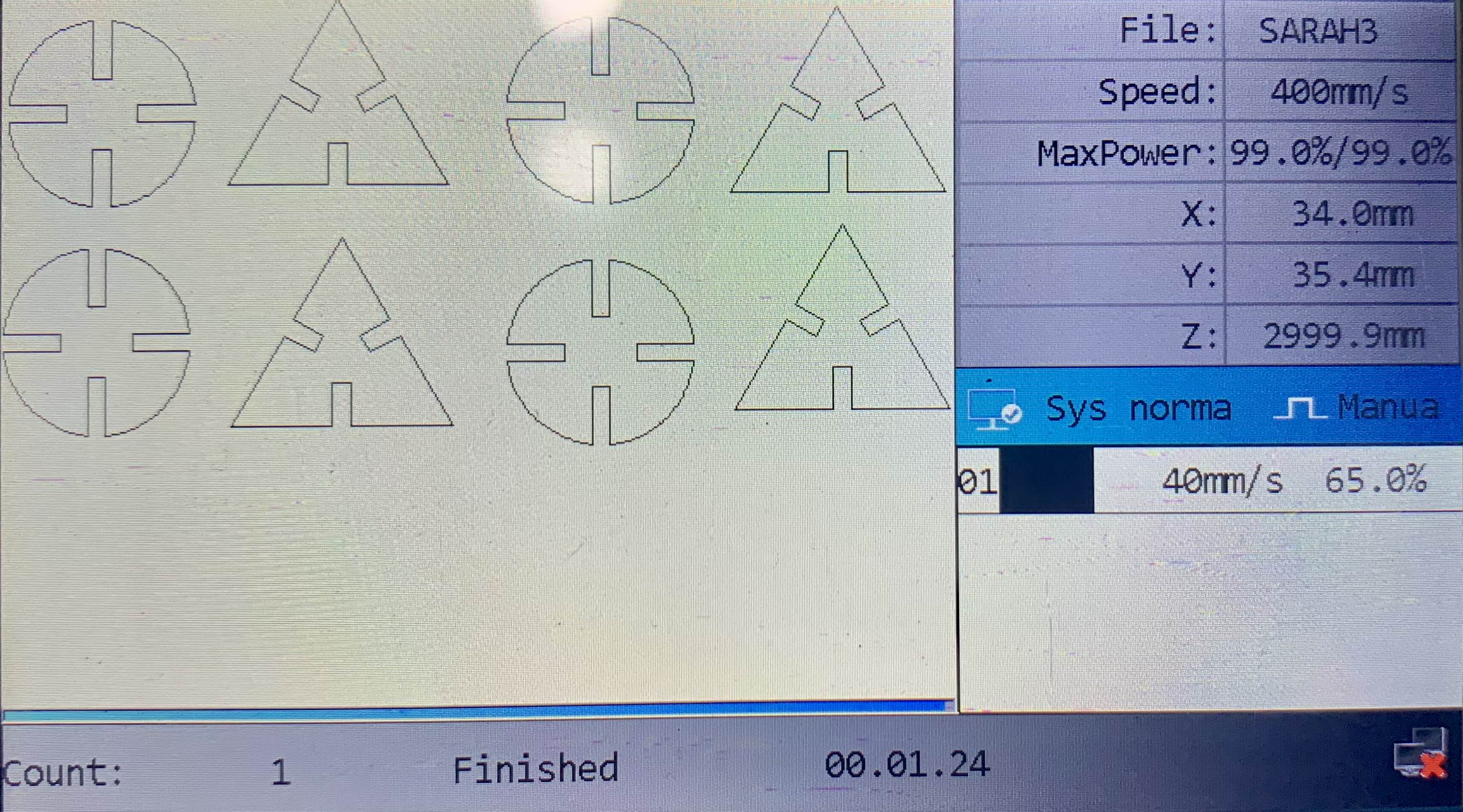
To cut out the design on the laser-cutting machine, I followed the same steps I did during Group Assignment 1, the first step of which is opening up our DXF file on RDWorks, configuring the speed, power and cut settings, then downloading the file to the machine:
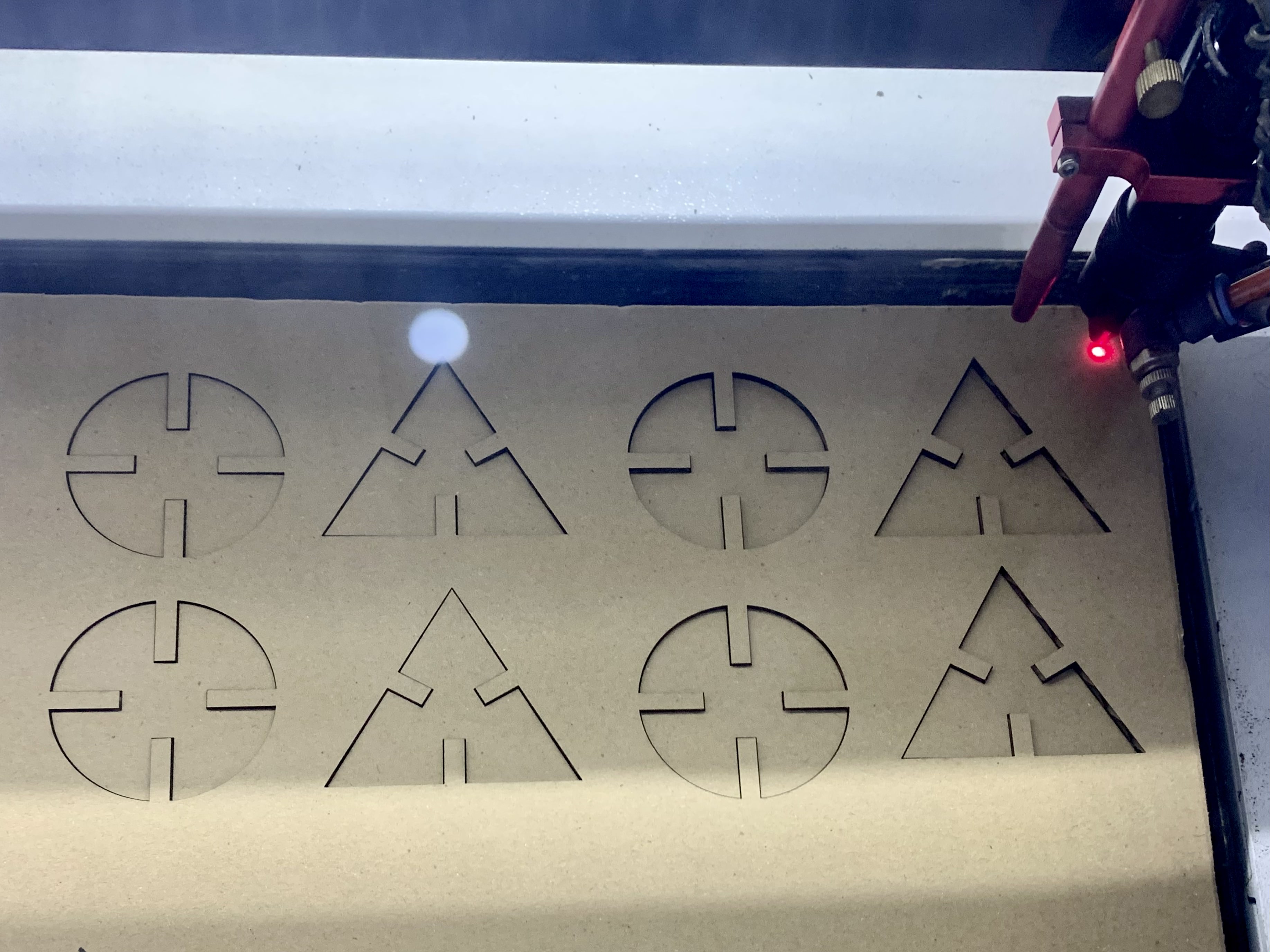
Next, we will have to set the origin and display the frame of where it will cut the cardboard, as we explained in Group Assignment 1. We can finally start cutting now!
This is how it turned out when it was done:
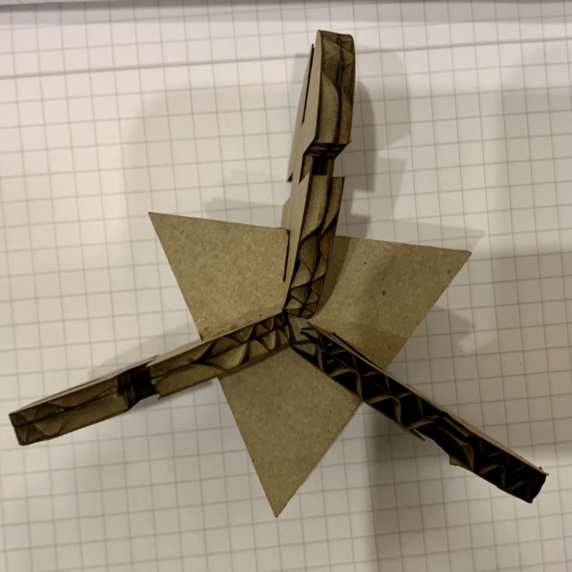
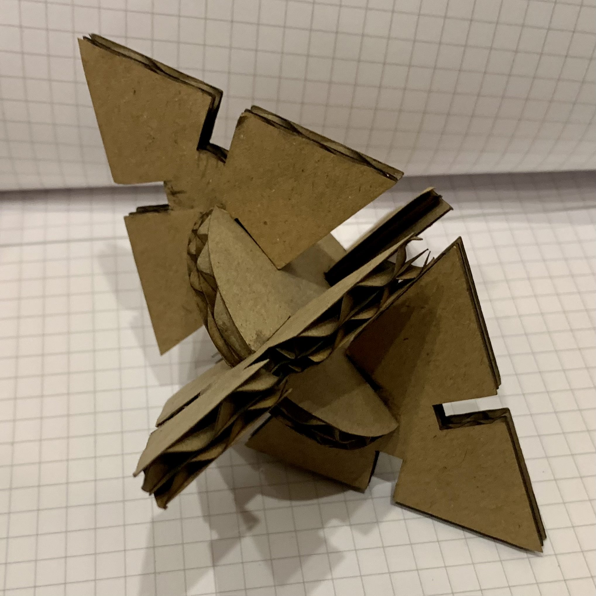
Assembling the Final Press-Fit Design
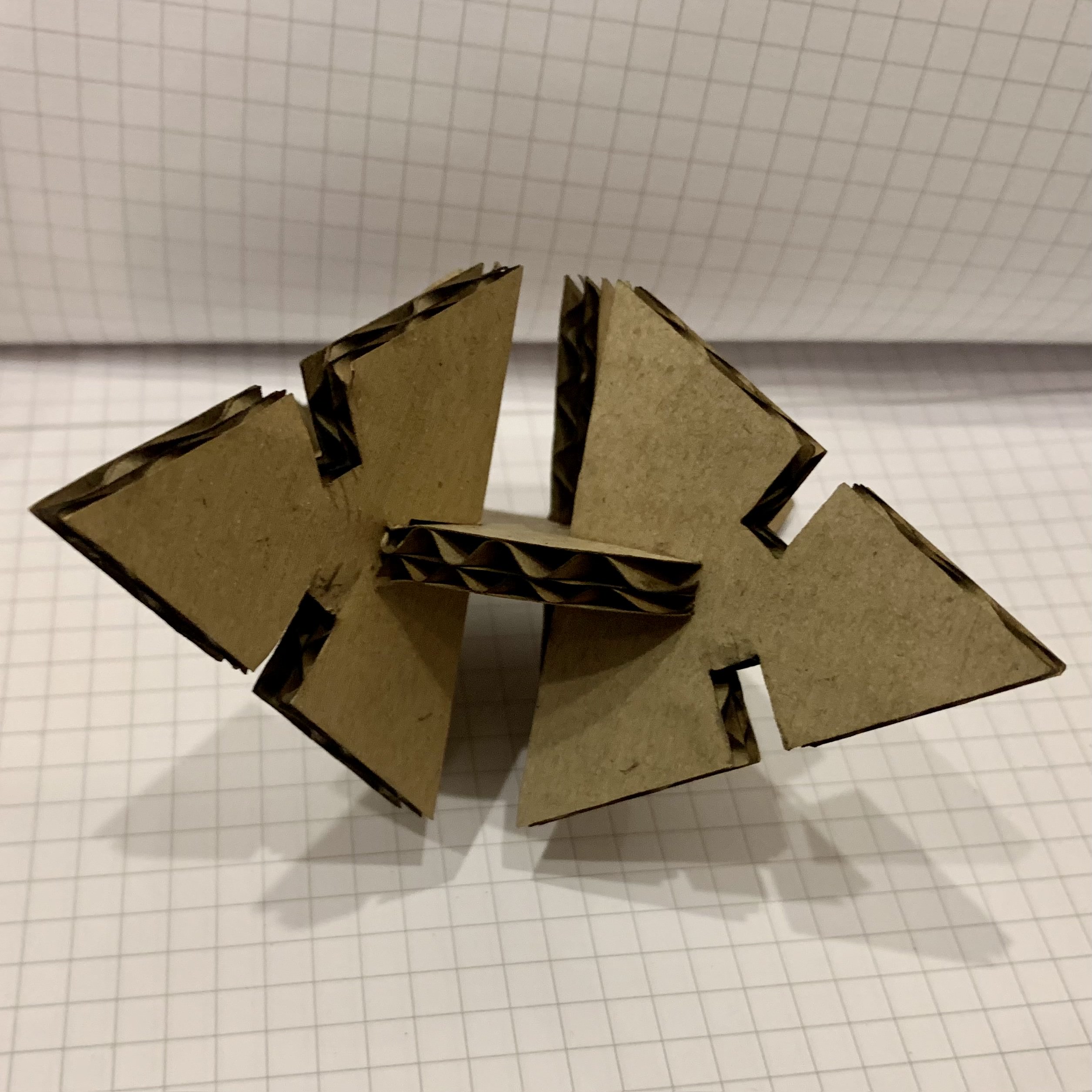
I made my design simple enough but with two different shapes to be able to arrange them in different ways together. This was one of the ways that I did:
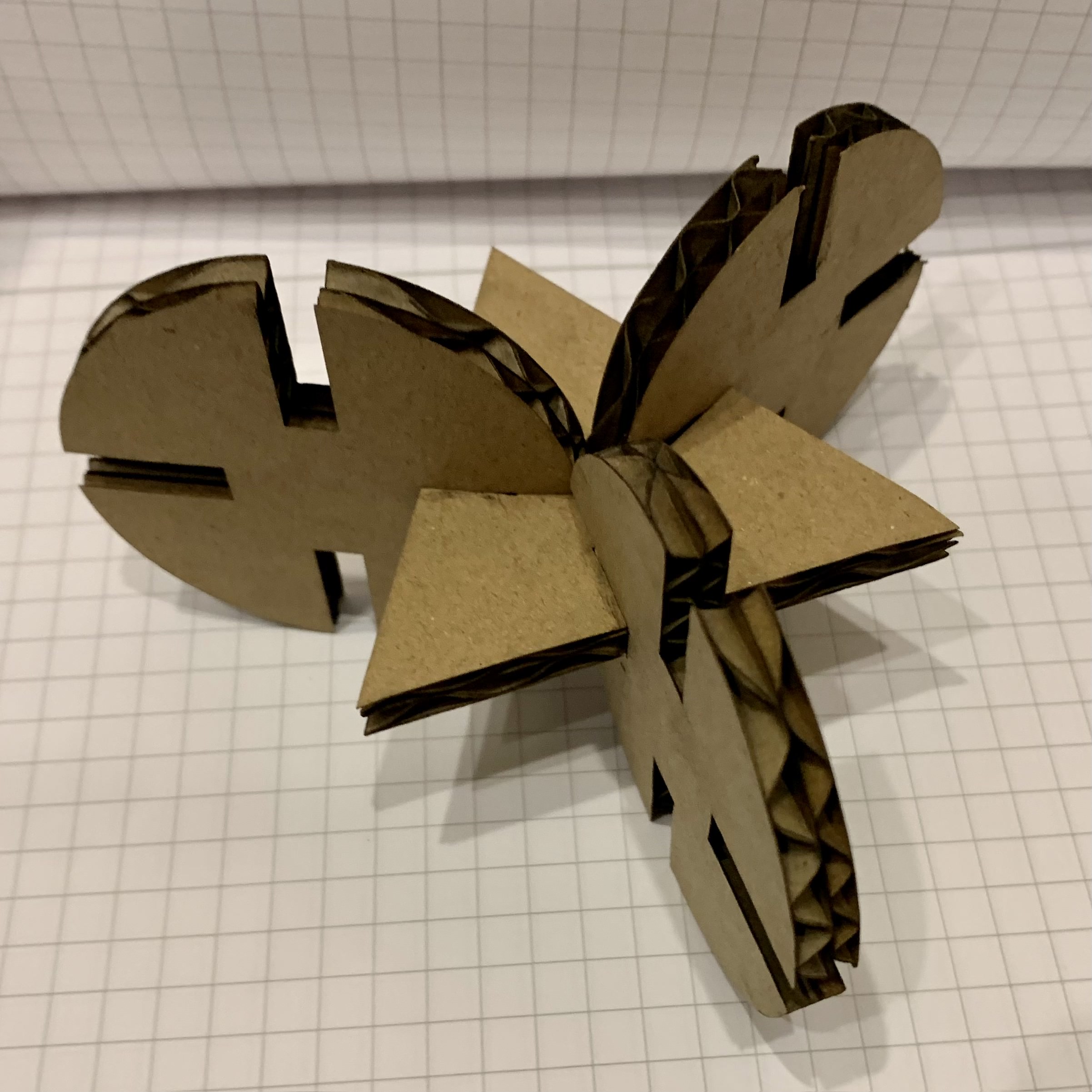
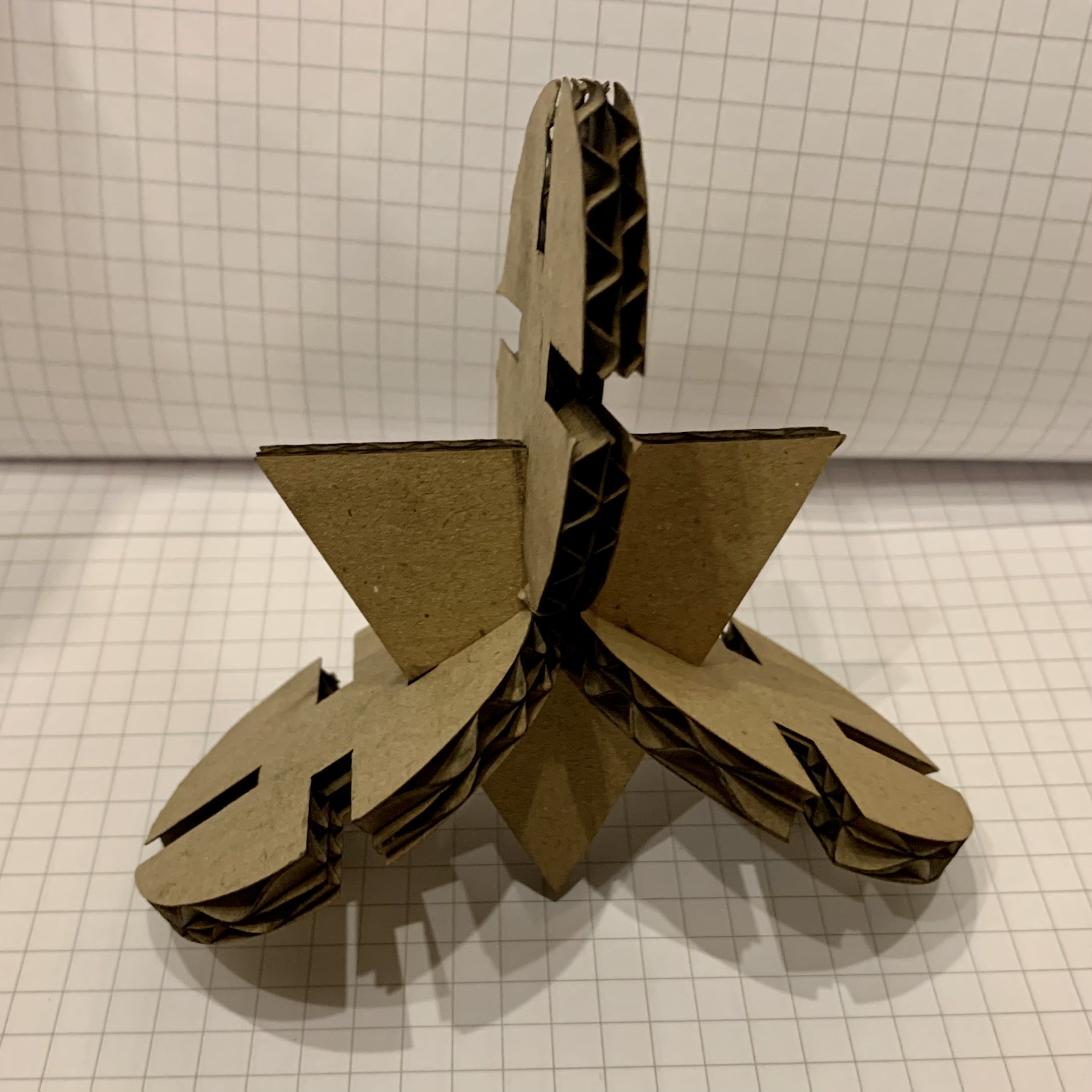
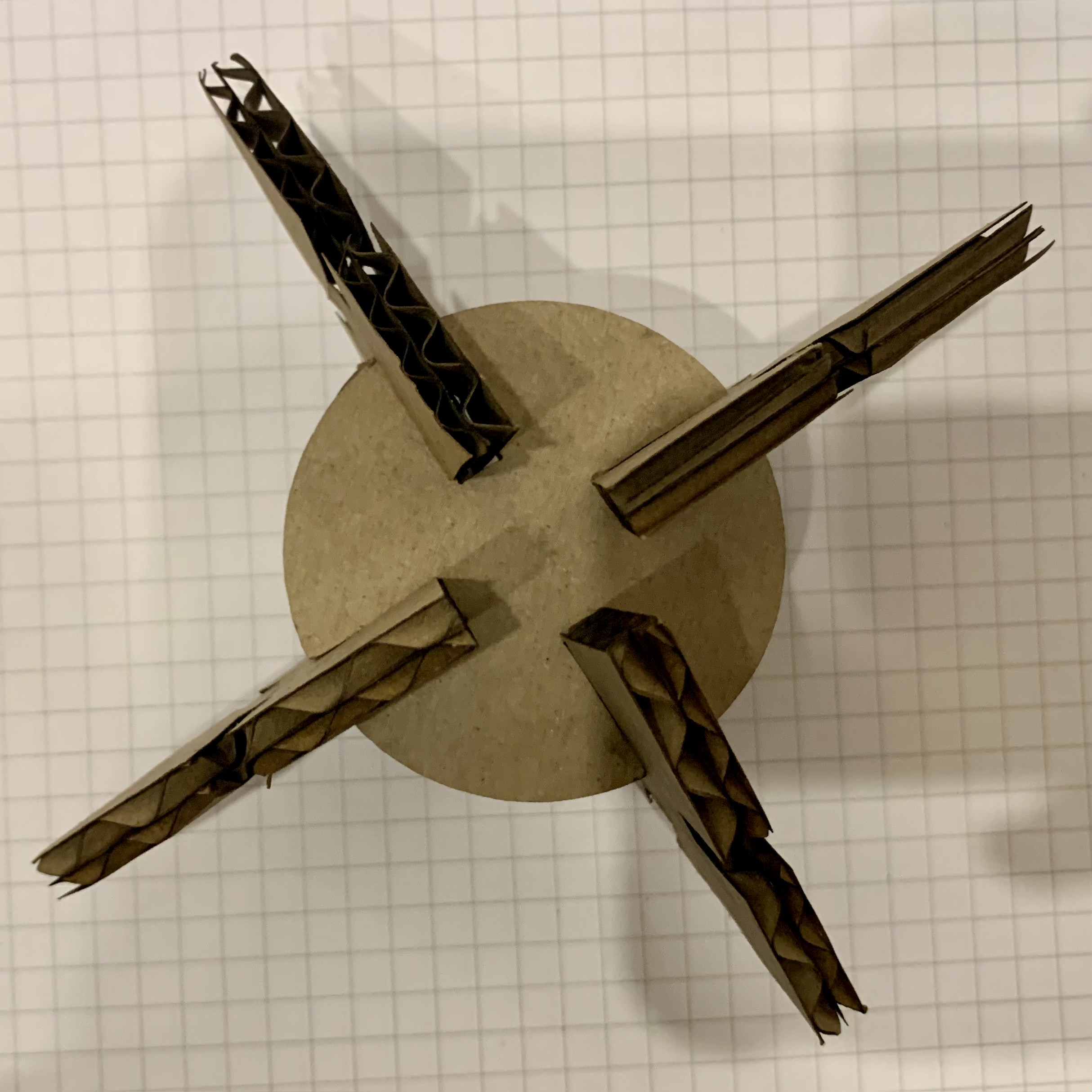
The benefit of having done the group experiments was that I was able to create a press fit design where these two different shapes can fit together in different arrangements due to the joints that I created.
Vinyl-Cutting
Facts About the Machine
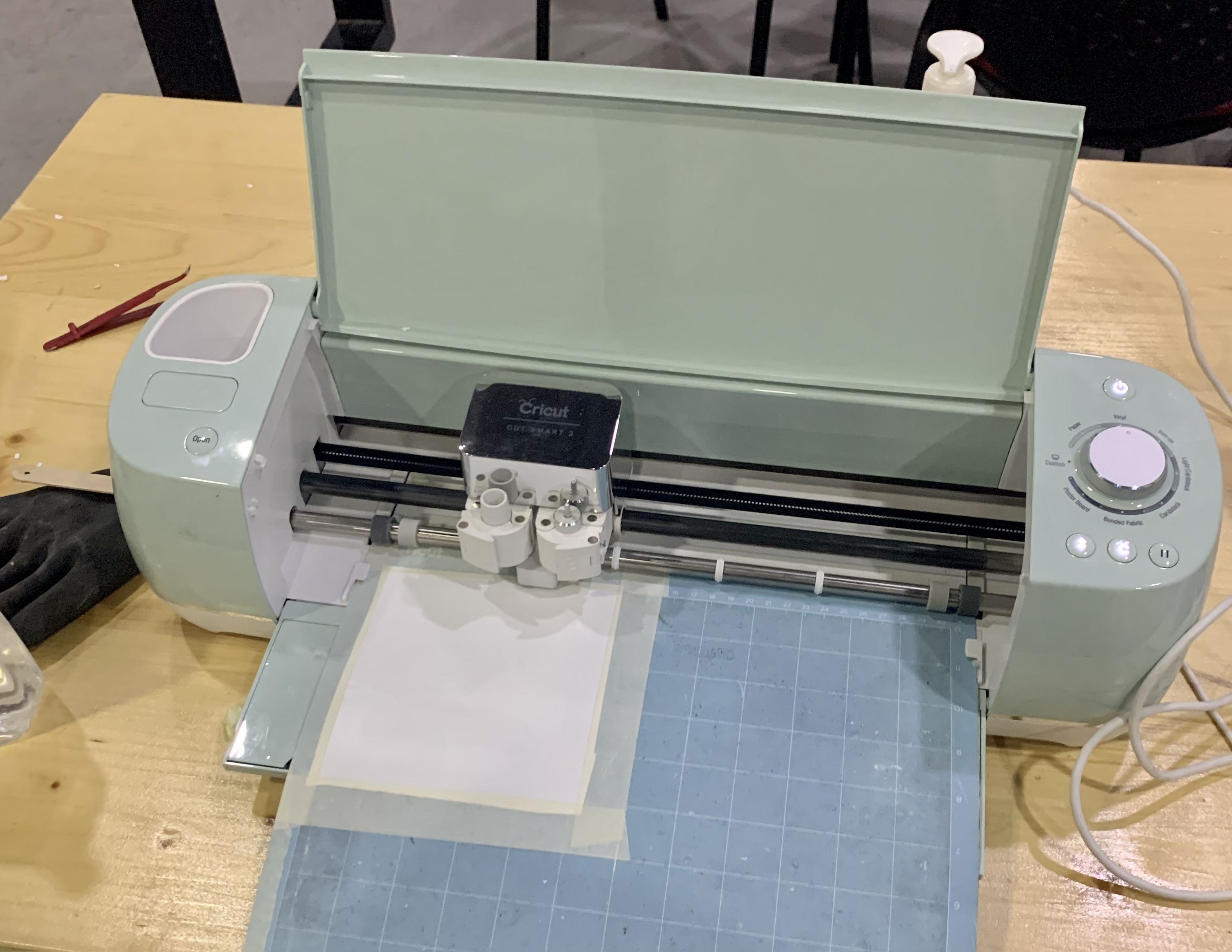
The vinyl-cutting machine we used was the Cricut Explore Air 2, which cuts everything from cardstock, vinyl and iron-on to specialty materials like glitter paper, cork, and bonded fabric. To use the machine for cutting, the following materials are necessary, and some are included with the machine:
- LightGrip Machine Mat, 12 in x 12 in (30.5 cm x 30.5 cm)
- USB cable
- Power adapter
- Fine-Point blade
- Masking tape
The material being cut must be taped onto the mat using the masking tape, while the blade acts as a razor and is used to cut out the designs onto the material. To upload designs to the machine, we will use the complementary software, Cricut Design Space, and connecting your laptop to the machine with the USB cable.
The Cricut site also provides a list of the materials that can be cut on each of their machines, as well as the blades needed to be used for them here. For our work, we will only be cutting our designs out onvinyl, which requires the fine-point blade and must be a maximum thickness of 2 mm for our machine. To cut thicker material, you may need to alter the pressure settings to fully cut through the material.
Group Assignment: Iron-On Fab Academy T-Shirt
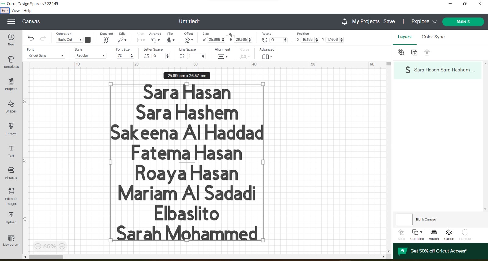
For this assignment, we started by writing out all the names of the Fab Academy Batch 8 Students (that’s us!) onto Cricut Design Space. We will be ironing on this text onto a t-shirt after it is cut.
To prepare to start cutting with the machine, we must first stick on the thick vinyl to the mat, with the matte side facing up. This is because we will need to iron on the letters to the t-shirt with the letters being oriented in the correct direction (from left to right).
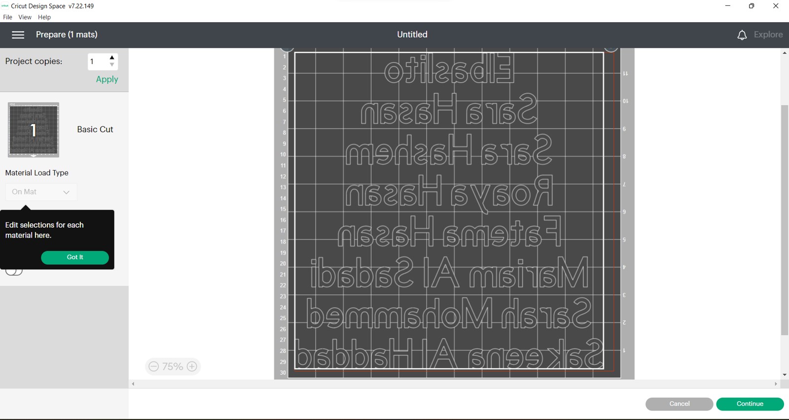
We will also be flipping the text in the software for it to cut out the design correctly.
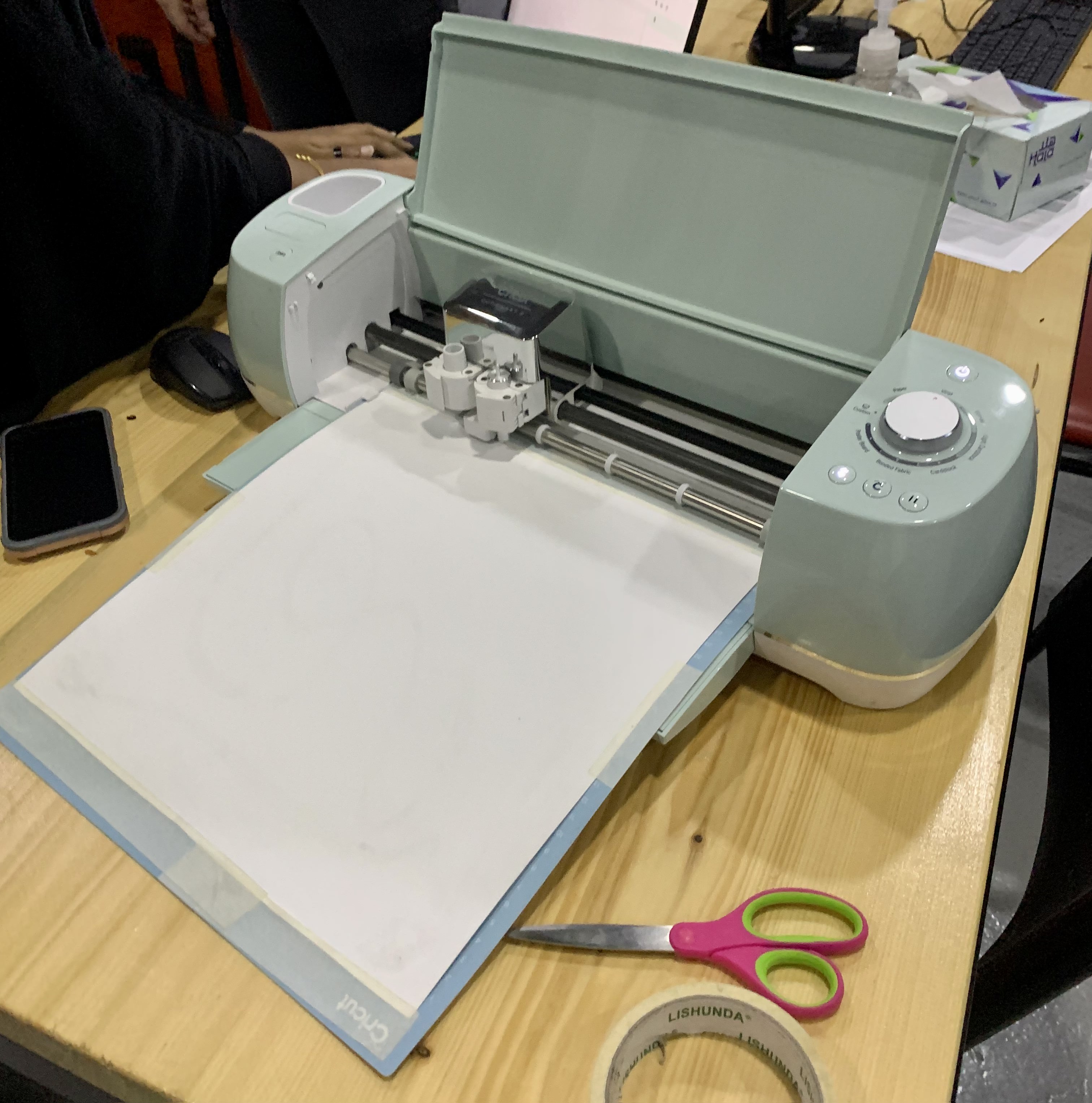
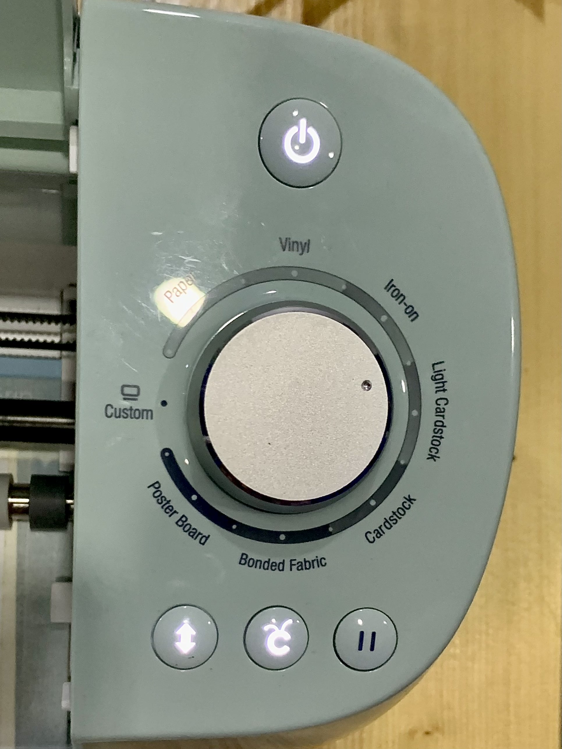
Finally, to start cutting, we will first align the mat with the material onto the machine, positioned under the blade, and click the button to configure it, which will make the machine grab onto the mat:
Then, after downloading the design to the machine, we can now turn the dial to vinyl and click the button to start cutting:
After some time, the design will be fully cut out. It won’t be entirely clear until we use tools (e.g. tweezers) to pull out the outline around the names, then use transfer paper to pick up each of the names and stick them onto the t-shirt.
After sticking on the names, we can then use an iron to bind it to the fabric of the t-shirt. This was the final result:

Note
The photo of the finished t-shirt was done with a gold vinyl that is thicker than the one used in the process photos, since in our first attempt the thinner white vinyl did not transfer onto the t-shirt correctly.
Individual Assignment: Vinyl Laptop Sticker
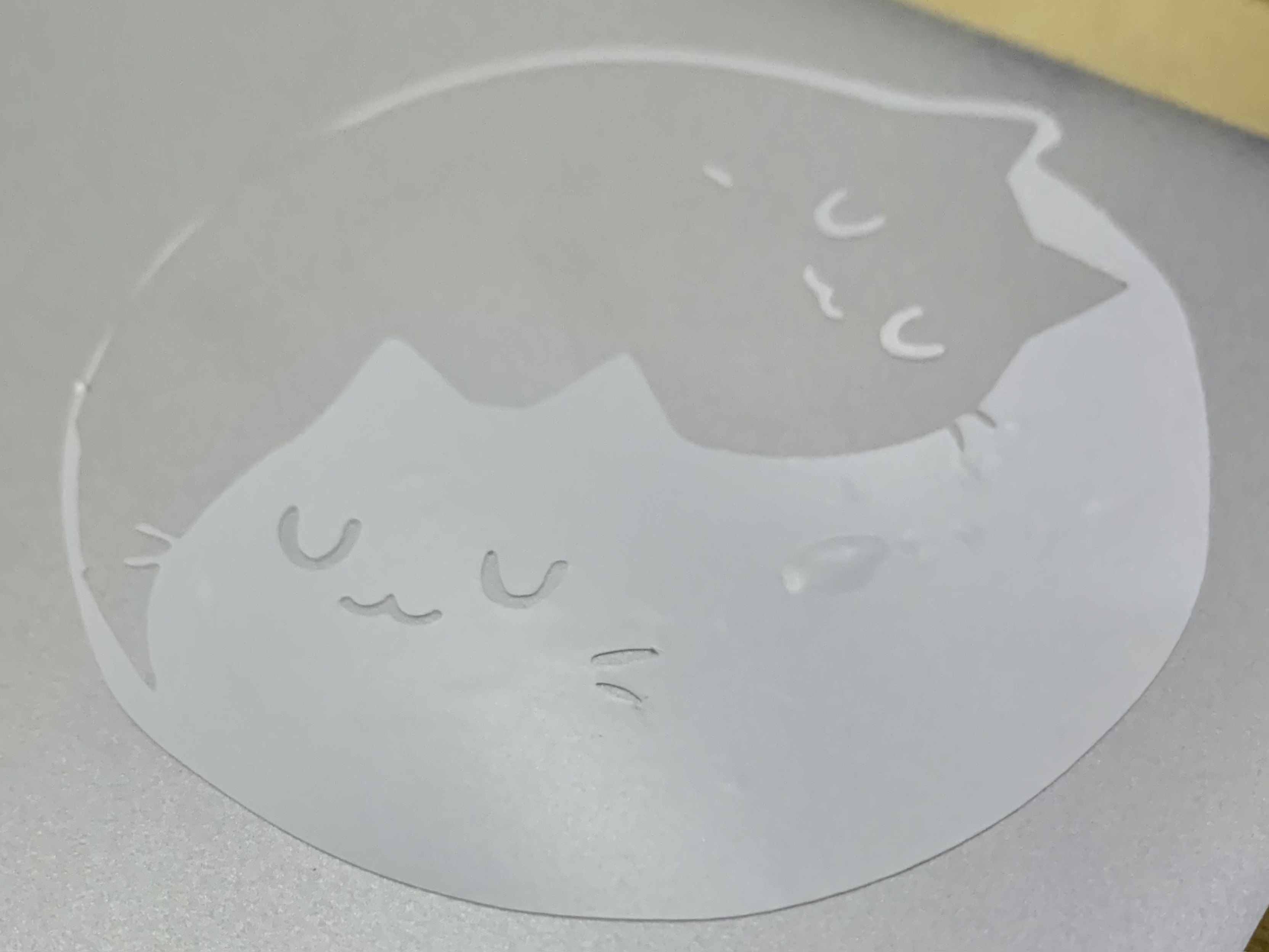
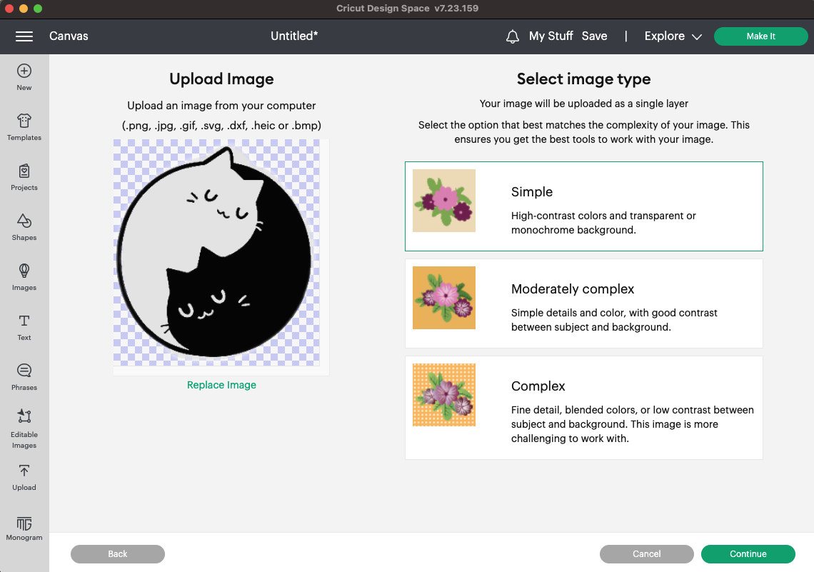
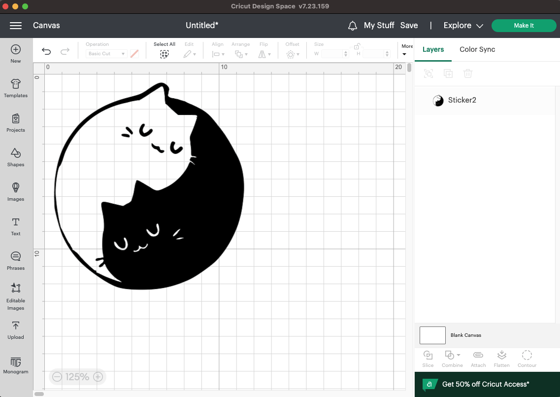
I first started out by choosing simple and cute artwork that I wanted to use a sticker for my laptop. I ended up choosing these adorable Yin and Yang cats!

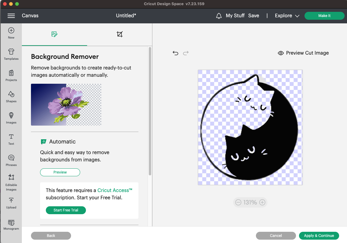
To prepare it for cutting, I opened up Cricut Design Space and uploaded the artwork I chose. Following the easy and quick steps, I prepared the design by making sure the outline would be perfect by removing the black (or the Yin!) cat and the black features of the white cat.
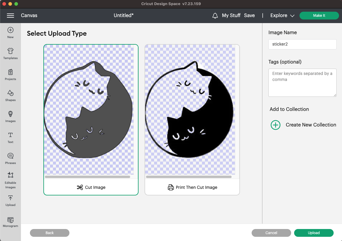
Finally, I imported the artwork to the canvas and resized it to the fit the dimensions I wanted for my sticker:
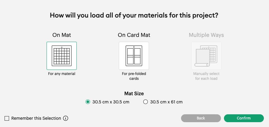
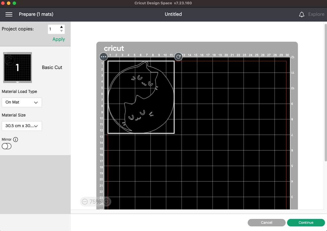
When I was satisfied with it, I clicked on Make It and chose the dimensions of the mat I will be using and edited any necessary settings:
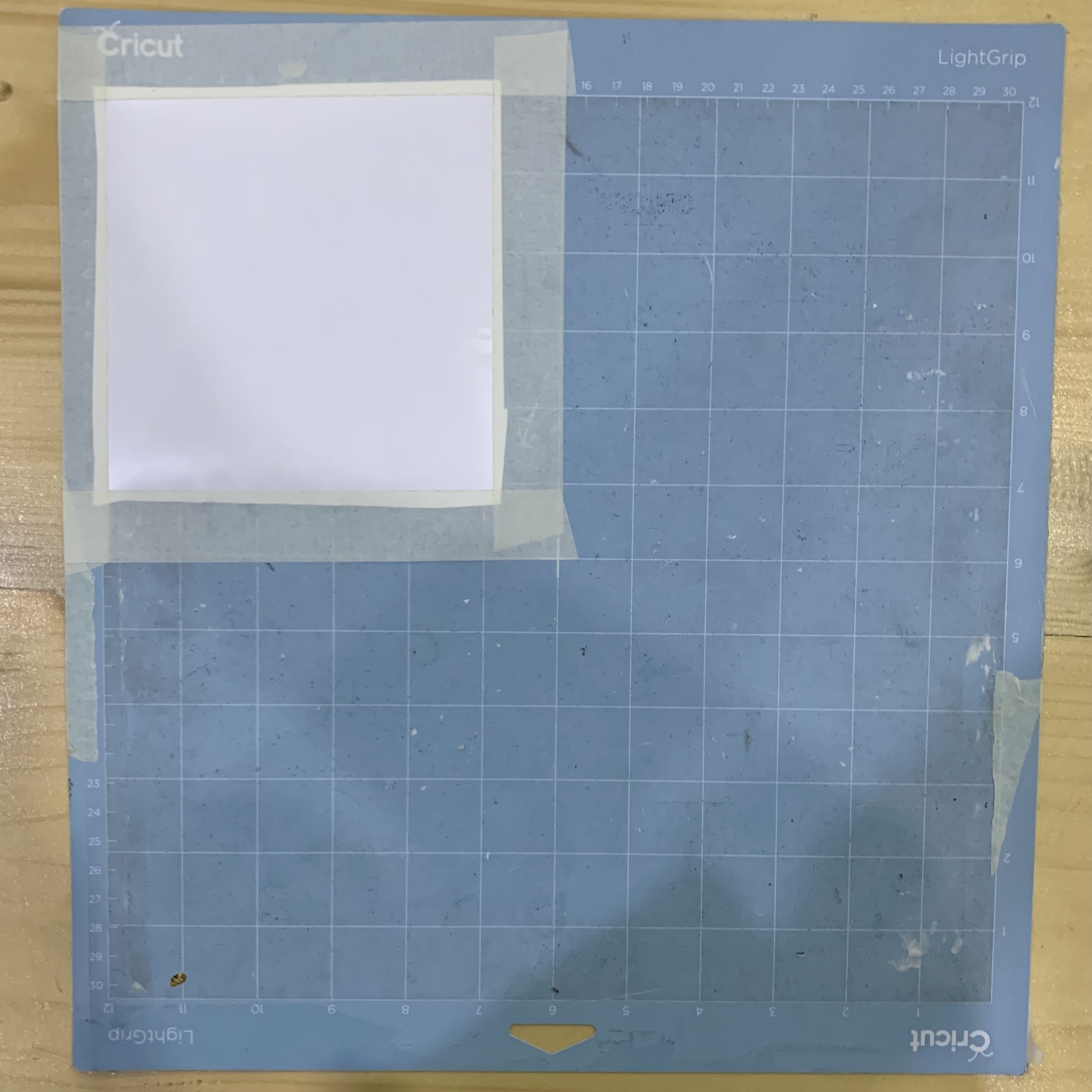
I then connected the vinyl-cutting machine to my laptop and cut out a piece of vinyl that was slightly bigger than the sticker and stuck it onto the mat. I followed the steps from the group assignment to cut out my sticker design.
The machine cutting out my sticker:
Finally, I started peeling off any parts of the sticker I did not need. I used the same tools that were used in the group assignment to delicately peel apart the pieces.
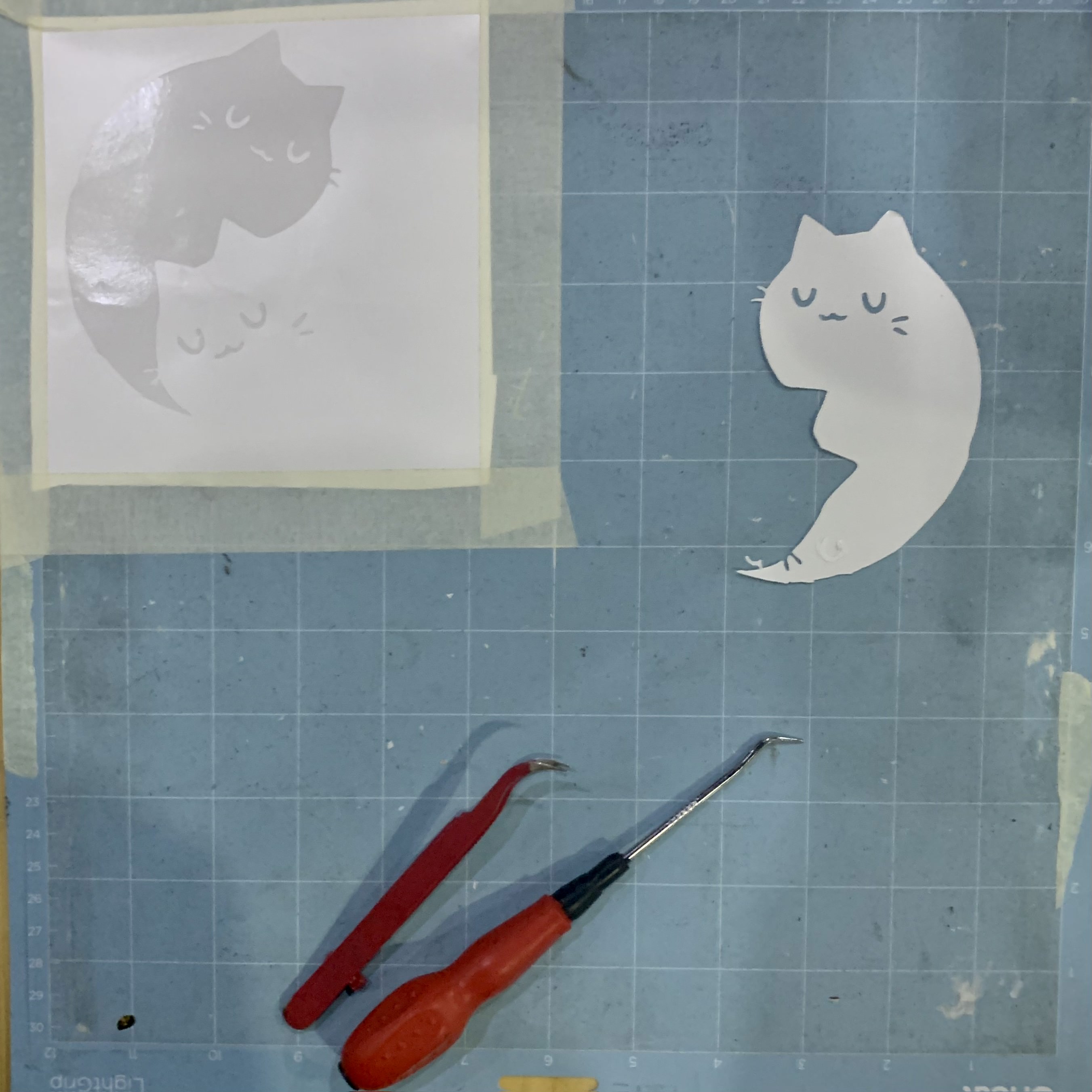
Since the black cat’s facial features and whiskers are not connected to the rest of the sticker and the outline of the sticker is thin on one side, I will need to use transfer paper to align my sticker design correctly onto my laptop.
Finally, I smoothed out the sticker onto my laptop surface and carefully peeled away the transfer paper. I had some air bubbles in my sticker, but I love how it turned out and I’m considering painting them in the future to look like a calico cat since their spots will hide the air bubbles!