2. Computer Aided design
Week Objective:
- Model (raster, vector, 2D, 3D, render, animate, simulate, …) compress your images and videos, and post it on your class page.
Throughout the program we will use different machines that required a design to work on. Therefore, this week our instructor have introduced us to a bunch of programs to use and learn like Tinkercad, Cuttle, Inkscape and Fusion 360.
To cope with the corona pandemic, my university have fully moved to deliver all their courses online. Therefore, I used several software to create visual representations for anything. For instance, Tinkercad was used to visualize digital logic gates and electronic circuits.
Thus, throughout this week I have experimented more with 2D and 3D Software:
Tinkercad
Tinkercad is an online collection of software tools from Autodesk that enable complete beginners to create 3D models. This CAD software is based on constructive solid geometry (CSG), which allows users to create complex models by combining simpler objects together. As a result, this 3D modeling software is user-friendly and currently enjoyed by many. Tinkercad is a good alternative to other 3D modeling software because if you do not need the more advanced features of these solutions.
Testing Phase
General Guidance to start your design:
Click on the “Create New Design” button as shown below:
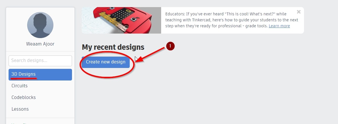
The following user interface Will be displayed:
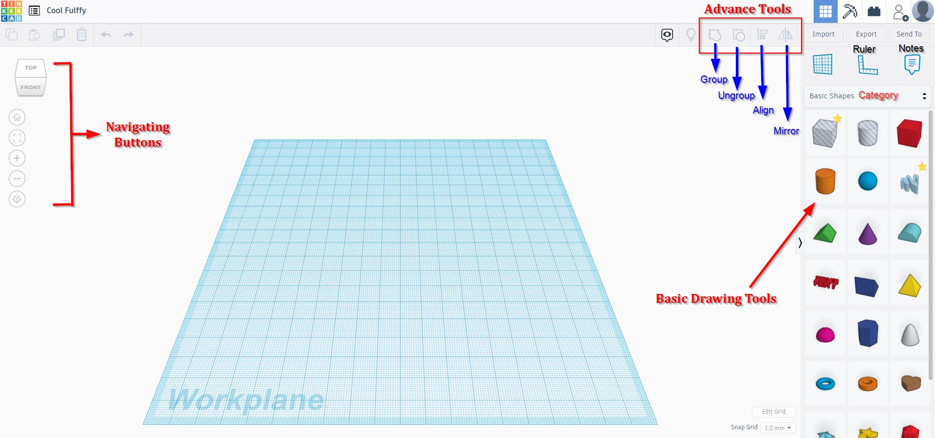
Therefore, we will try now the tools available:
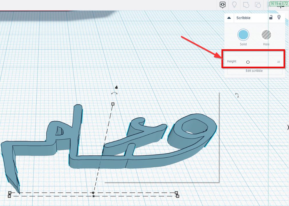
- “Drop Scribble” tool:
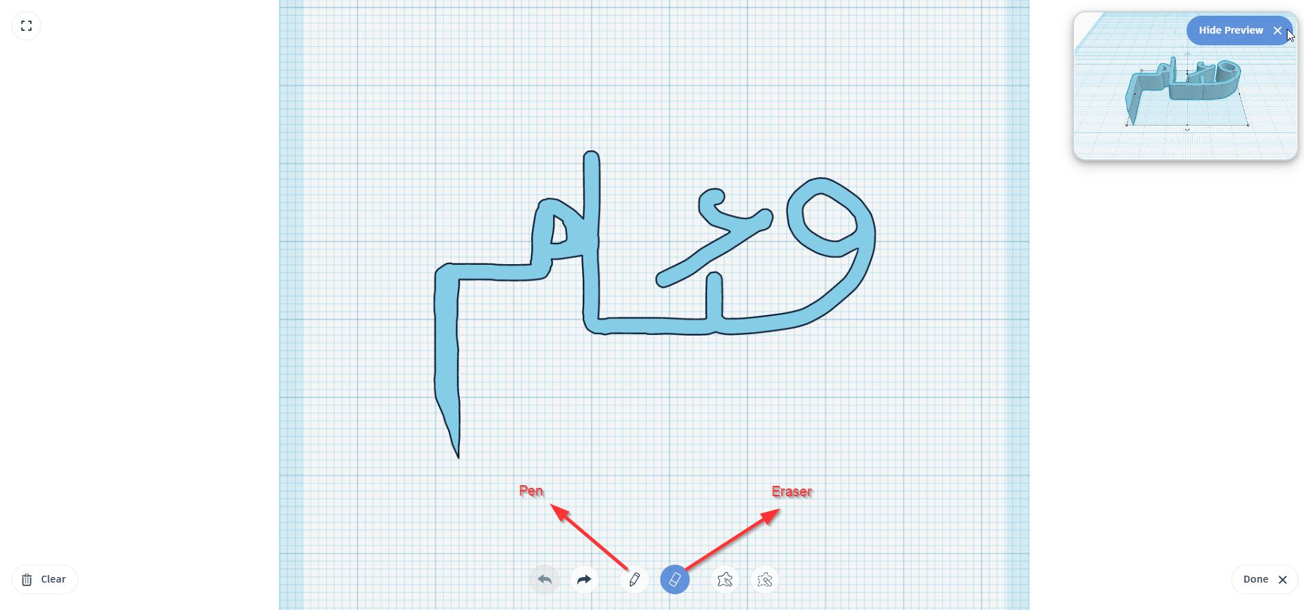
After clicking on the “Scribble” Button from shapes menu, found here:
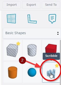
I Drew my name in 2D and click on “Done” Button. Then, the 2D shape was converted to 3D shape and we can adjust the height.
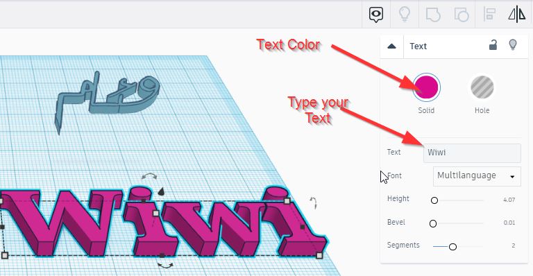
- Drop Text:
Clicking on the “Text” Button from shapes menu, I wrote random text:
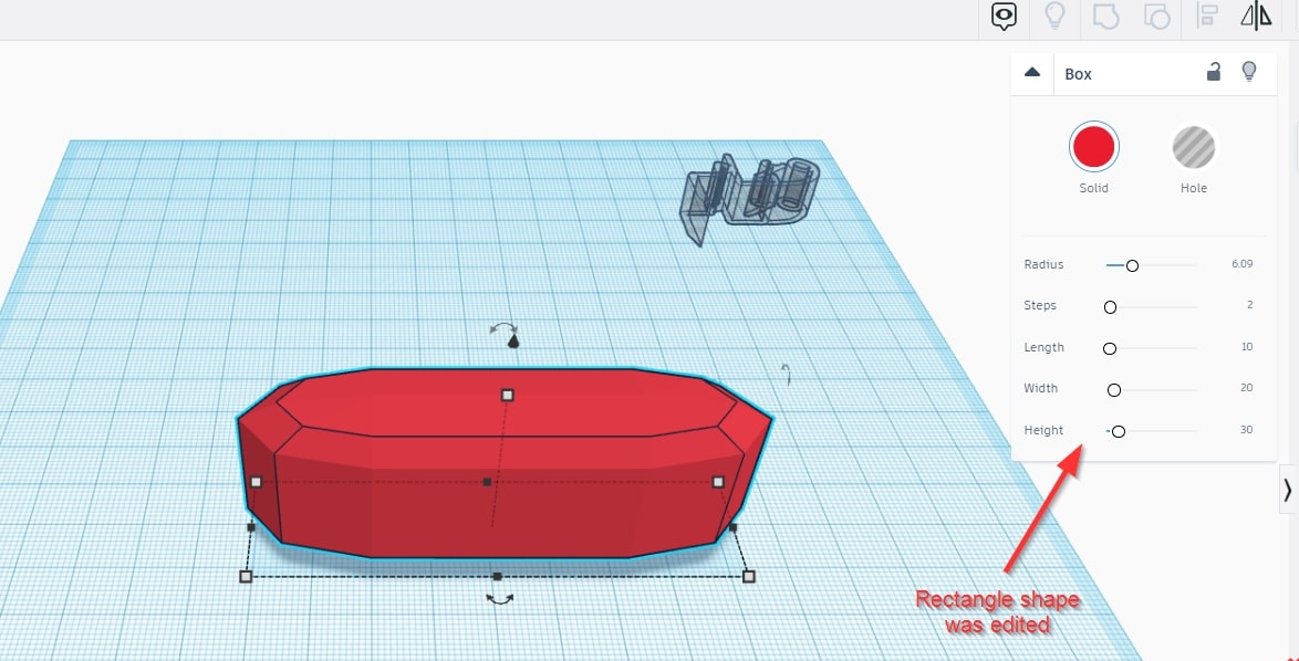
- Drop Shape:
To examine how object are flexible, I have dropped a square and edit its value:
- Grouping Tool:
To merge two shapes I have dropped two shapes (square & circle). Then, both shapes were selected and combine by “Group” Button as shown below:
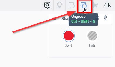
- Ungroup Tool:
To separate the two shapes, we select both shapes and use “Ungroup” button, as shown below:
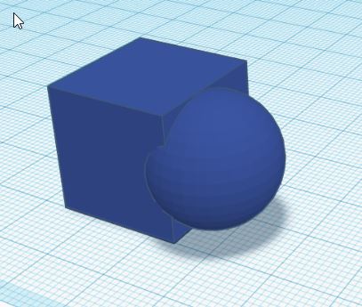
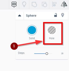
- Hole Tool:
To create a hole by the sphere in the square, you need first to set the sphere as “Hole” :
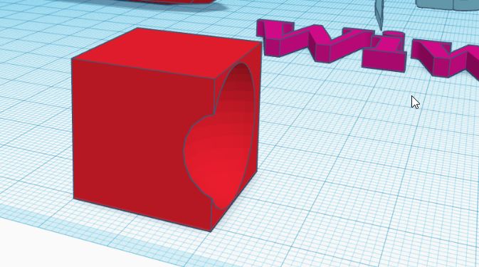
Then, place the sphere in the square were the hole is needed. Finally, click on the Grouping Button.
Designing Phase
To further challenge my self and explore the software tool, I designed a Benny Bear using the following Tutorial :
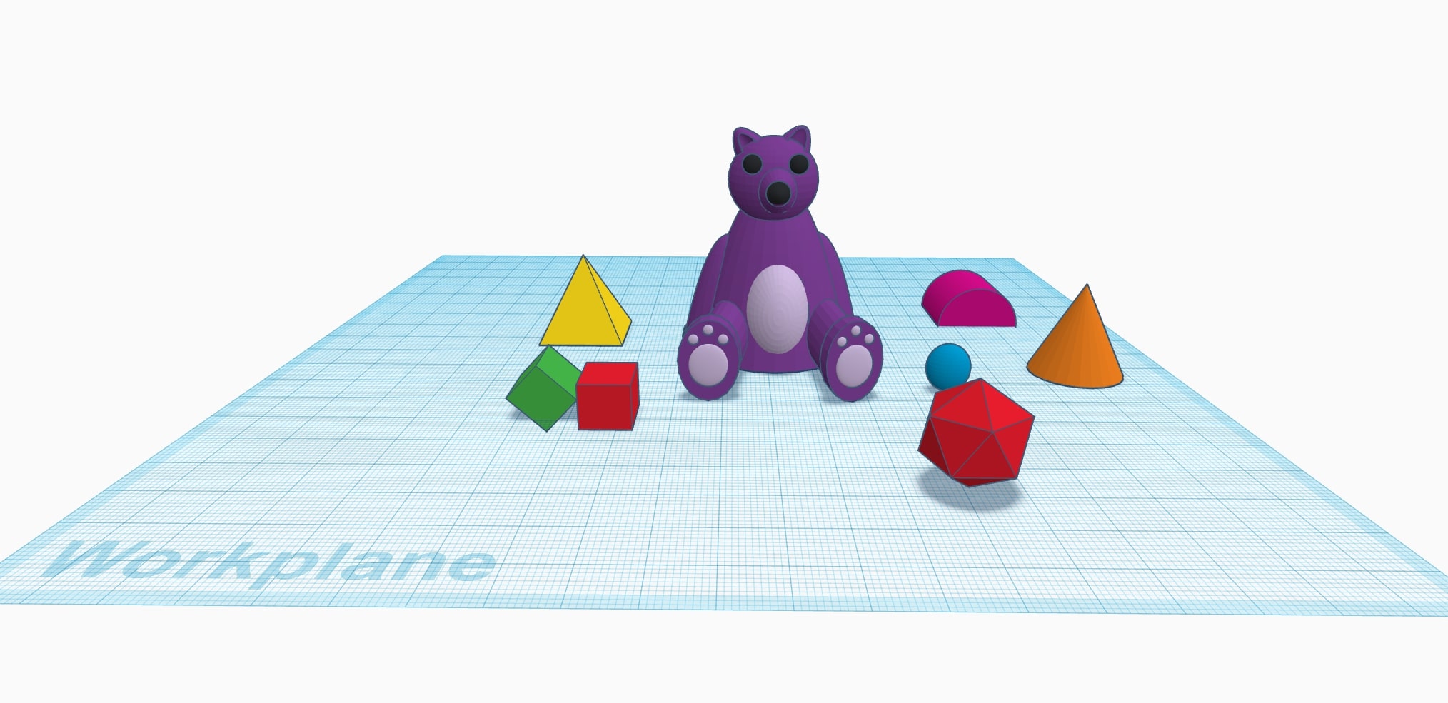
3D Preview:
Click here to download the design.
Cuttle
Cuttle is a vector editor with features for cut design like live modifiers, parameters, reusable components, and scripting.
Testing Phase
General Guidance to start your design:
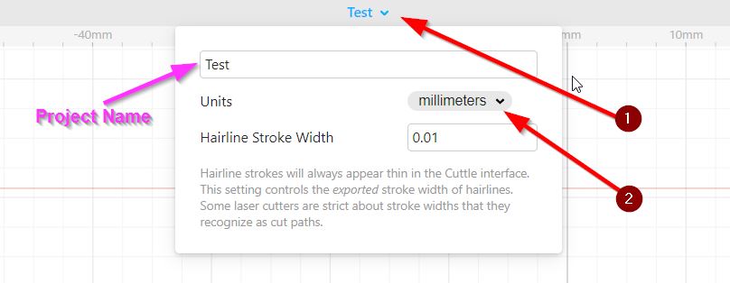
Create your account and click on the “New project” button. Then, the following user interface Will be displayed:
Change the measuring unit to what you desire from here:
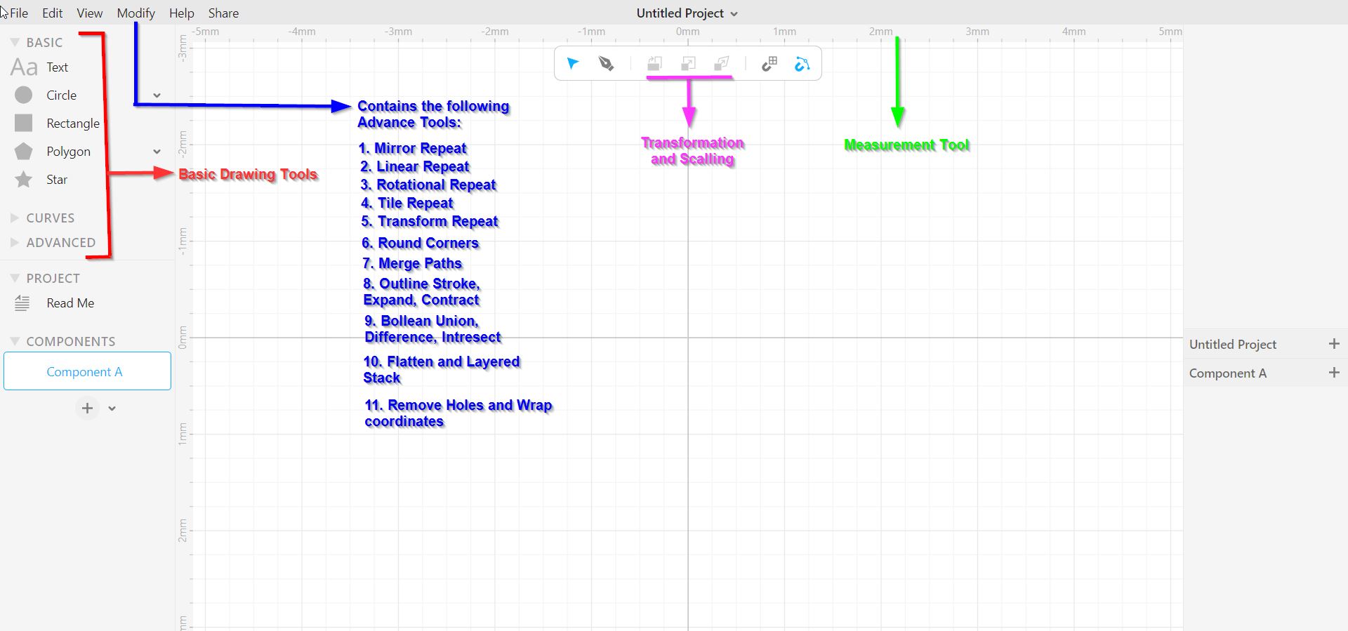
Therefore, we will try now the Main tools available:
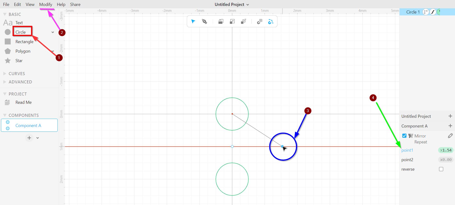
- Mirror Repeat:
The Circle was dropped in the center of the page. Then, “Mirror Repeat” button was selected from the Modify drop menu. An alignment tool will appear to place the mirroring line. Also, the location of the line can be precisely placed manually by changing the line points from the right-hand side section.
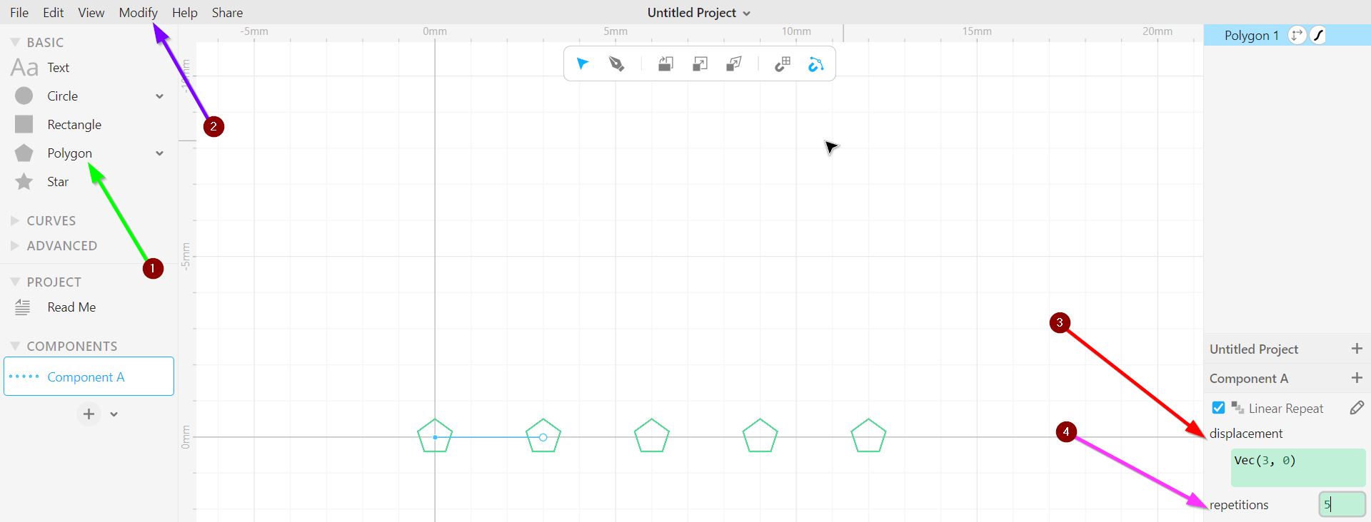
- Linear Repeat
The polygon was dropped in the center of the page. Then, “Linear Repeat” button was selected from the Modify drop menu. Users can modify the linear repetition form the right-hand side section. “Displacement” Button refers to the place were the repetitive shapes may be settle and the amount of shape’s repetition can be adjusted from “Repetition”. This following is an illustration of how I tried the linear tool:
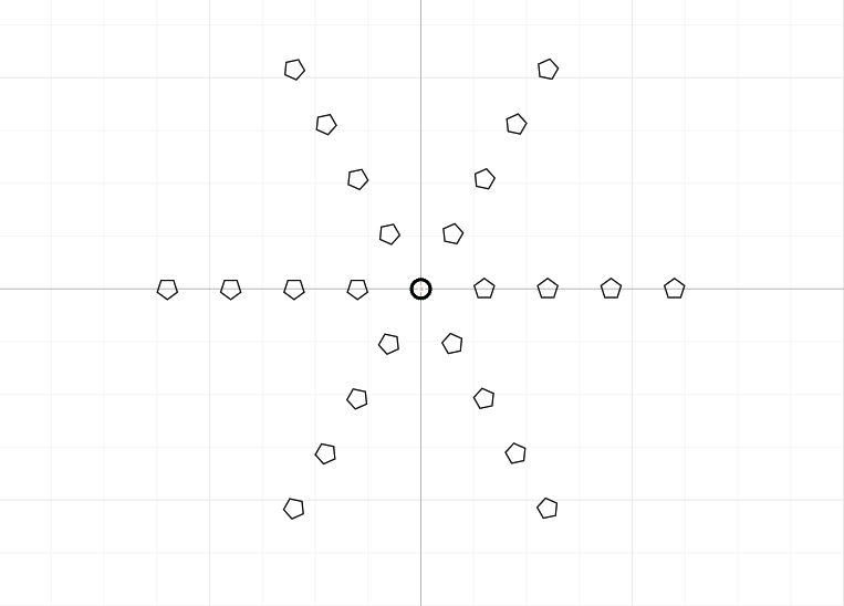
- Rotational Repeat:
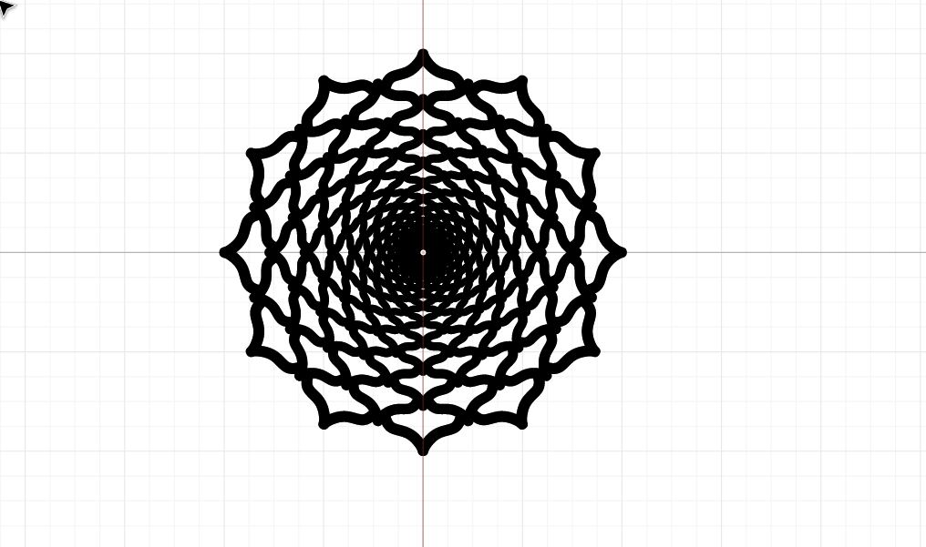
To rotate the shape in 360 degree, I have select the “Rotational Repeat” button from the Modify drop menu. I have viewed the following shape:
- Tile Repeat:
After I selected the “Tile Repeat” button from the Modify drop menu. I have noticed that this tool repeats every shape from its corner 16 times, as follows:
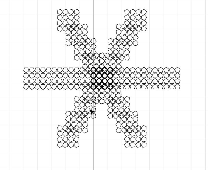
- Transform Repeat:
When I selected the “Transform Repeat” button from the Modify drop menu. At first the shape have transferred linearly 6 times. Therefore, I thought that it was similar to the tool used before “Linear Rotate”. However, I noticed that we can do much more things with it. For instance, We can change the rotation angle, scale, and skew form the right-hand side section. Therefore, I tested it by changing couple of things with the aim to have an “Ice Falling” image. This following is an illustration of how I tried the tool:
![]()
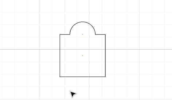
- Boolean Union
After I Dropped a square and circle, I selected “Boolean Union” to attach both shapes together. As follows:
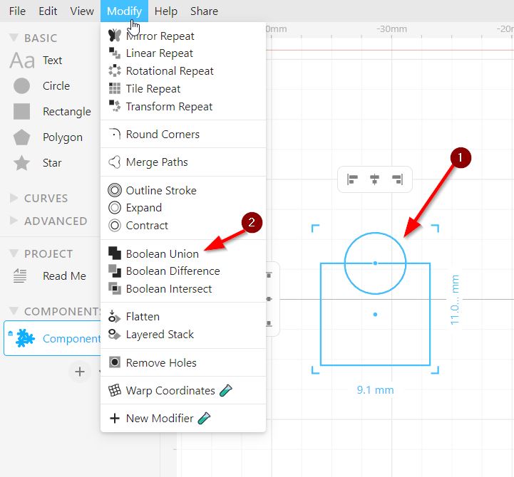
The Results:
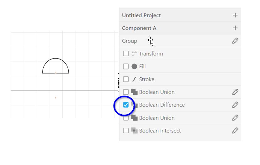
- Boolean Difference:
Using the same shape drawn above, I have selected “Boolean Difference” to detach the part were the two parts are shared. The results is:
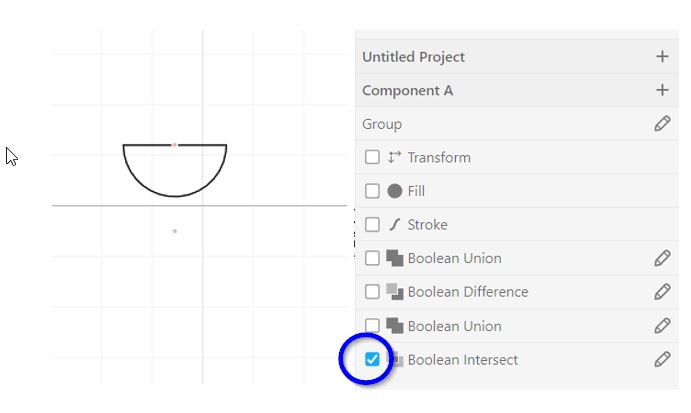
- Boolean Intersect:
Using the same shape drawn above, I have selected “Boolean Intersect” to keep the part were the two parts are shared. The results is:
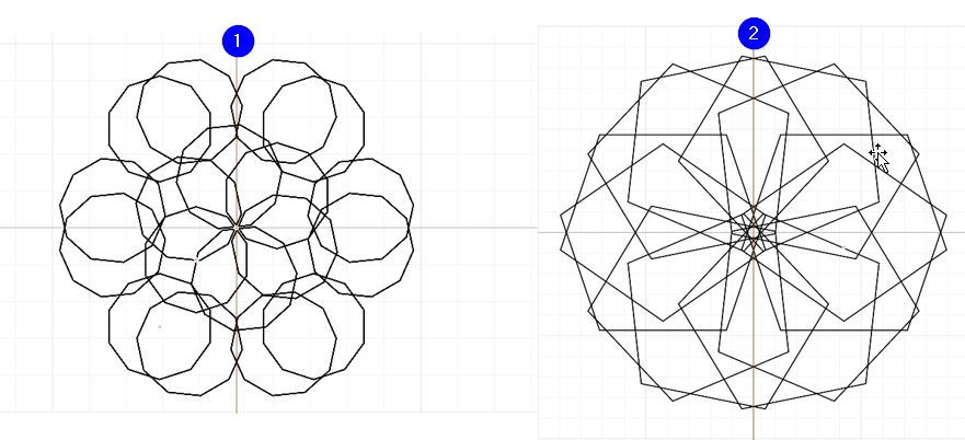
I will share here some of my other designing trials:
Designing Phase
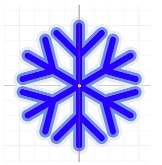
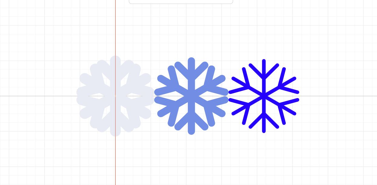
To further challenge my self and explore the software tool, I designed a Layered Snowflake using the following Tutorial :
Click here to download the design.
Note: Through this tutorial I have learnt that for cutting purposes, we can distribute the layers by clicking on: Modify -> Layered Stack -> Distribute
The following result is used for sending it to the laser cutter in future:
Searching through the internet I also found a YouTube video for designing a Succulent Coaster in Cuttle tutorial. So, I was so interested to try it and these are the results:
Click here to download the design.
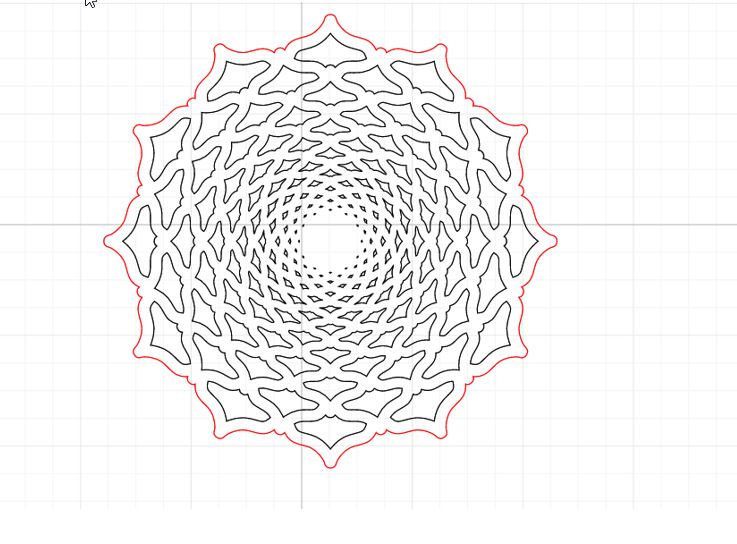
Note: Through this tutorial I have learnt that for cutting purposes, we can use “Convert paths” button to print the Succulent Coaster.
The following result is used for sending it to the laser cutter in future:
Inkscape
Inkscape is a free and open-source vector graphics editor licensed under the GP. It is used to create vector images, primarily in Scalable Vector Graphics (SVG) format. It runs on Linux, Mac OS X and Windows desktop computers.
Testing Phase
General Guidance to start your design:
After downloading the app and clicking it to open, the following screen will appear:
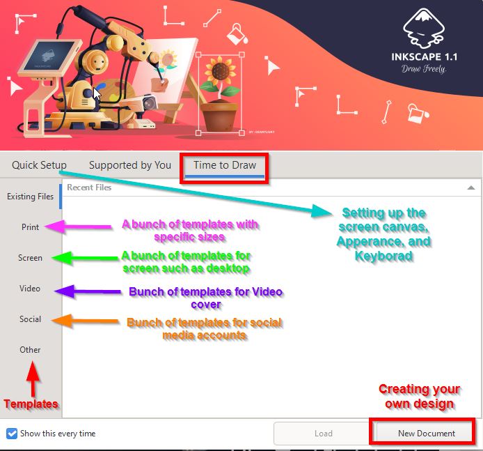
When the “New Document” button is selected, now lets try the tools available in the software:
Note: I have watch the following Tutorial to learn about the software tools.
- Fill and Stroke Menu:
After droping a rectangle shape, we can edit the software through the “Fill and Stroke” menu avaliable here:
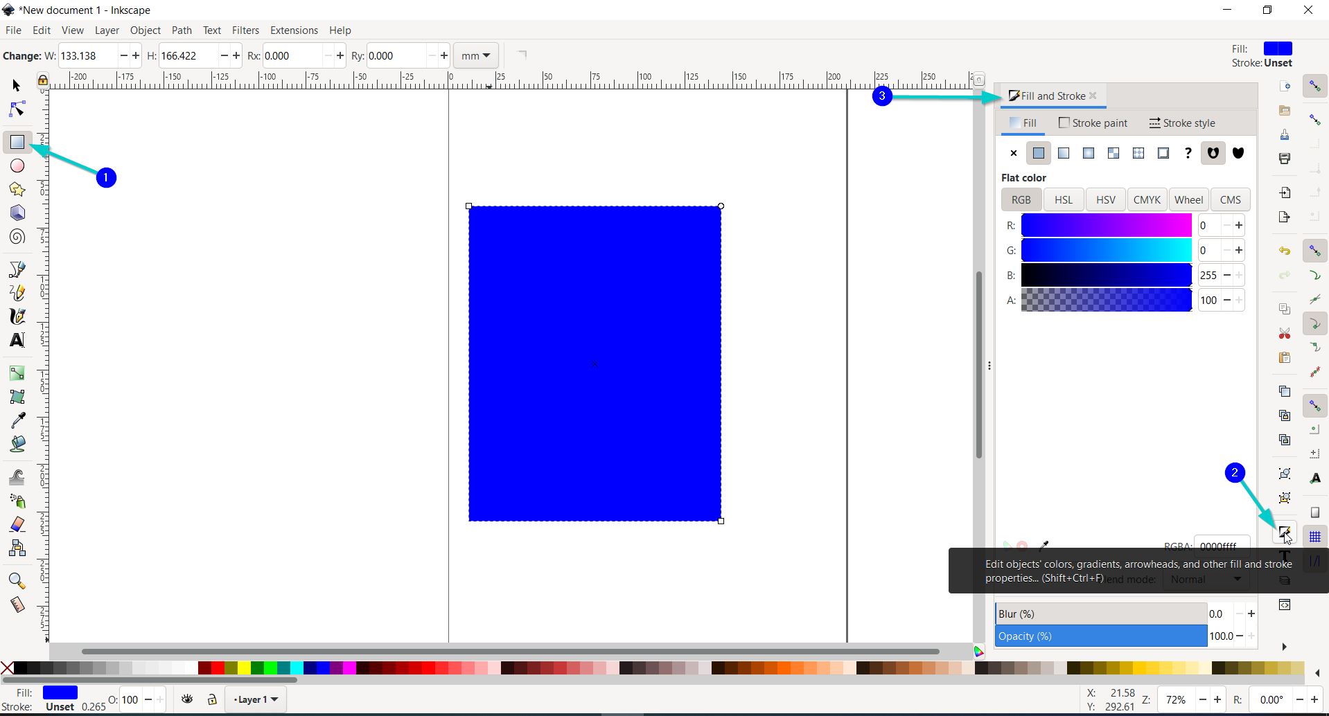
Note: “Fill” is the enternal color of the shape. “Stroke” iS the external color of the shape.
Shortcut: 1-You can change the Stroke’s color by clicking “Shift” then selecting any color from the color bar at the buttom of you screen. 2-To get rid of the Stroke click on “Shift” then select the red x from the color bar at the buttom of you screen.
- Linear Gredient:
Here you can edit the shape’s color by clicking on the “Linear Gredient” button then select the circle desired from the dashed line appeared.
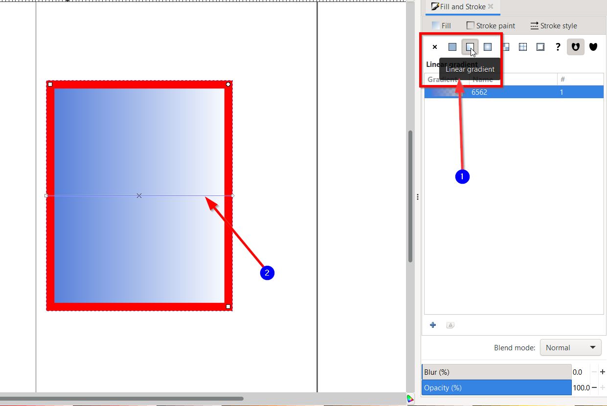
Then, using the weel you can easily choose the color.
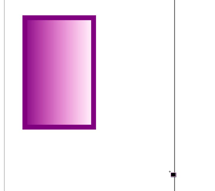
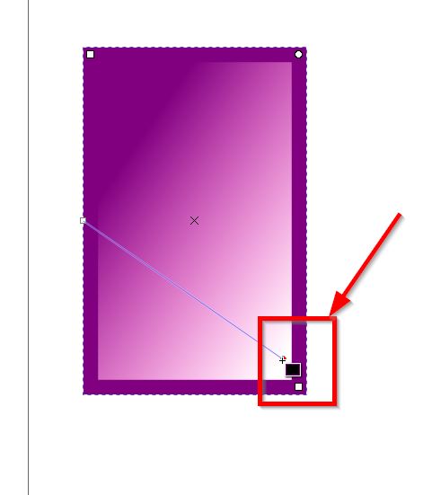
You can also change the direction of the color gradual by moving the circle. For instance:
- Alignment Menu and Holes
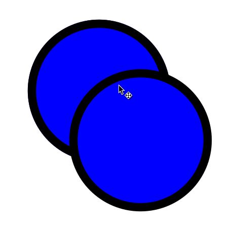
Step 1: The two circles were drawn and duplicated.
Note:
1-To draw a perfect circle you can select ctrl + shift
2-To dupliate the shape click on ctrl + d
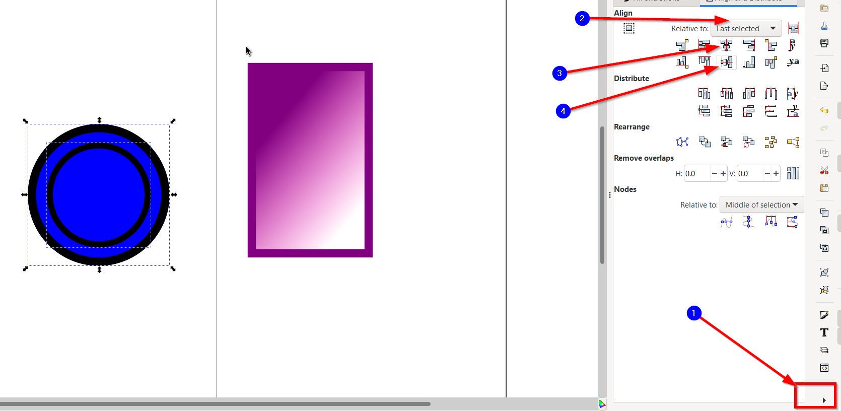
Step 2: Align the two circles:
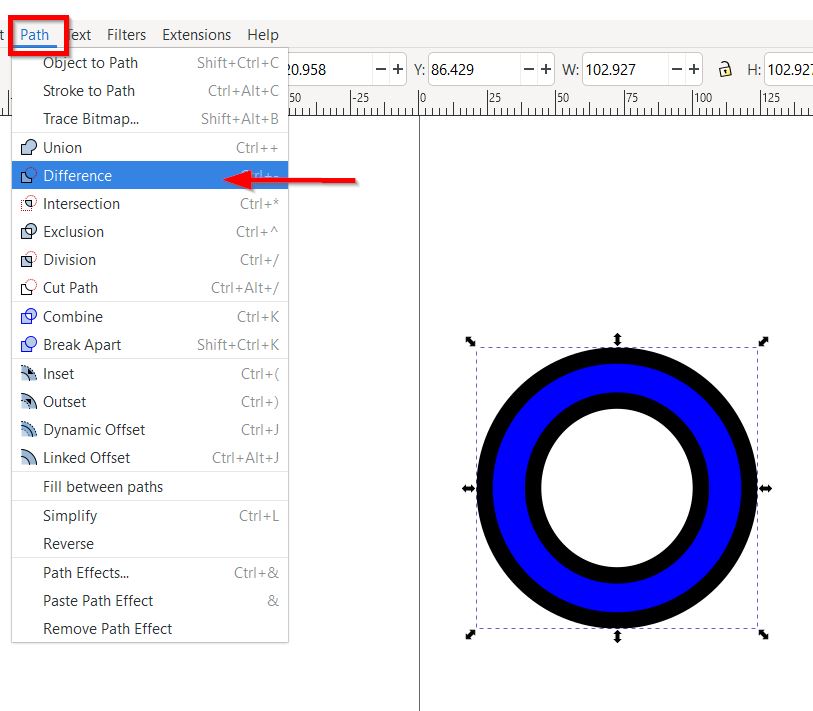
Step 3: Select both circles, then go to “Path” menu and select difference:
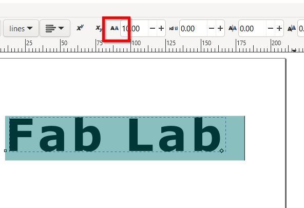
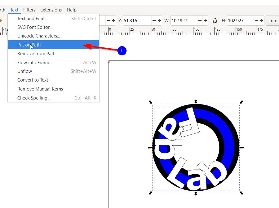
- Edit Text: Spacing and “Put on Bath”:
After Droping a text you can go and edit the spacing by clicking on the the following button:
Now to make the text around the circle created before; we will first align the shape and then select “Put on Bath” button. To have the following results:
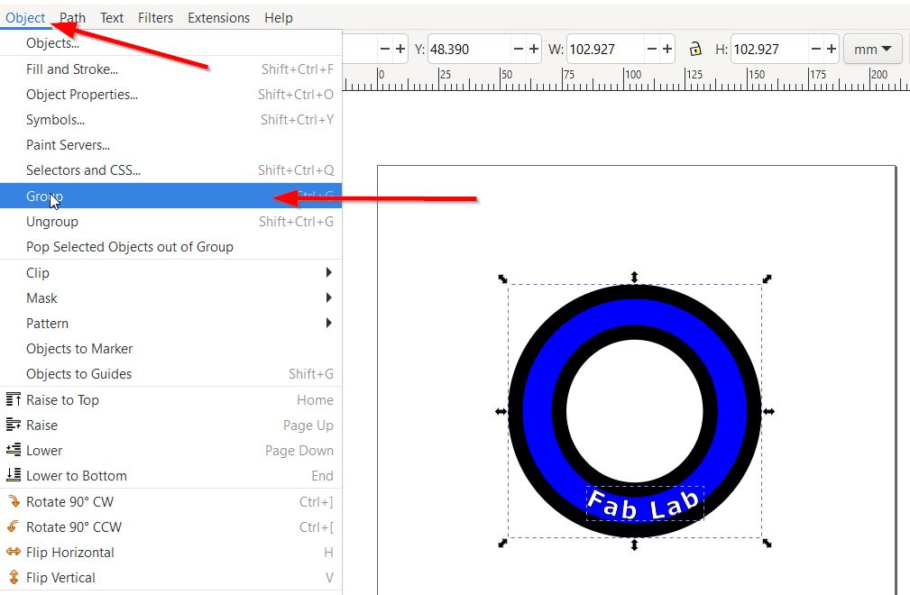
- Group objects:
To make the objects attach to each other we may use “Group” tool:
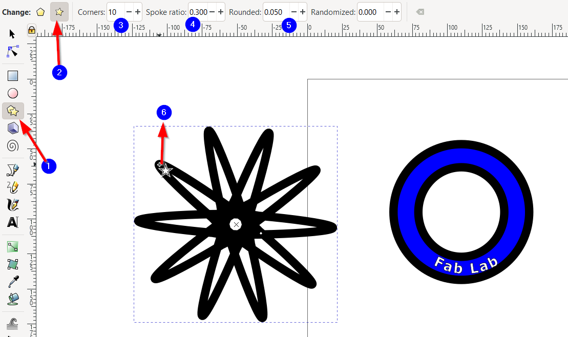
- Geometric Power:
The software gives you alot of geometric features for instance you can change the star shape by: 1-Changing the corners number 2-Spoke ratio 3-Shape rounding 4-Rotate the circle using the small circle appear on the shapes
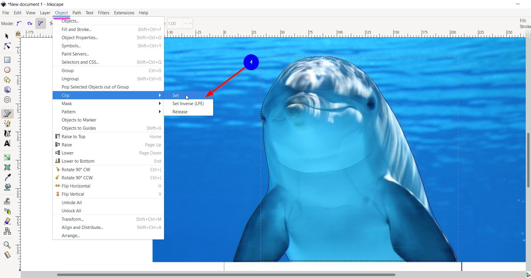
- Removing the picture’s Background using “Bezier” pen:
After Importing the image, use the bezier pen to trace the desired object.
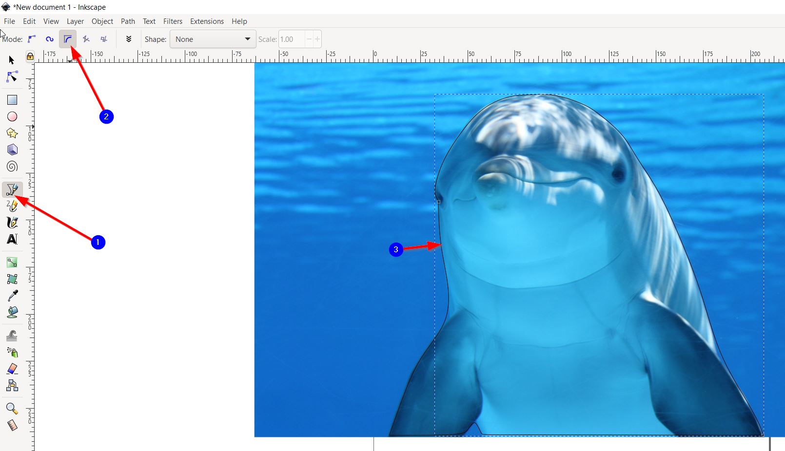
Then, used “clip” tool to remove the Background.
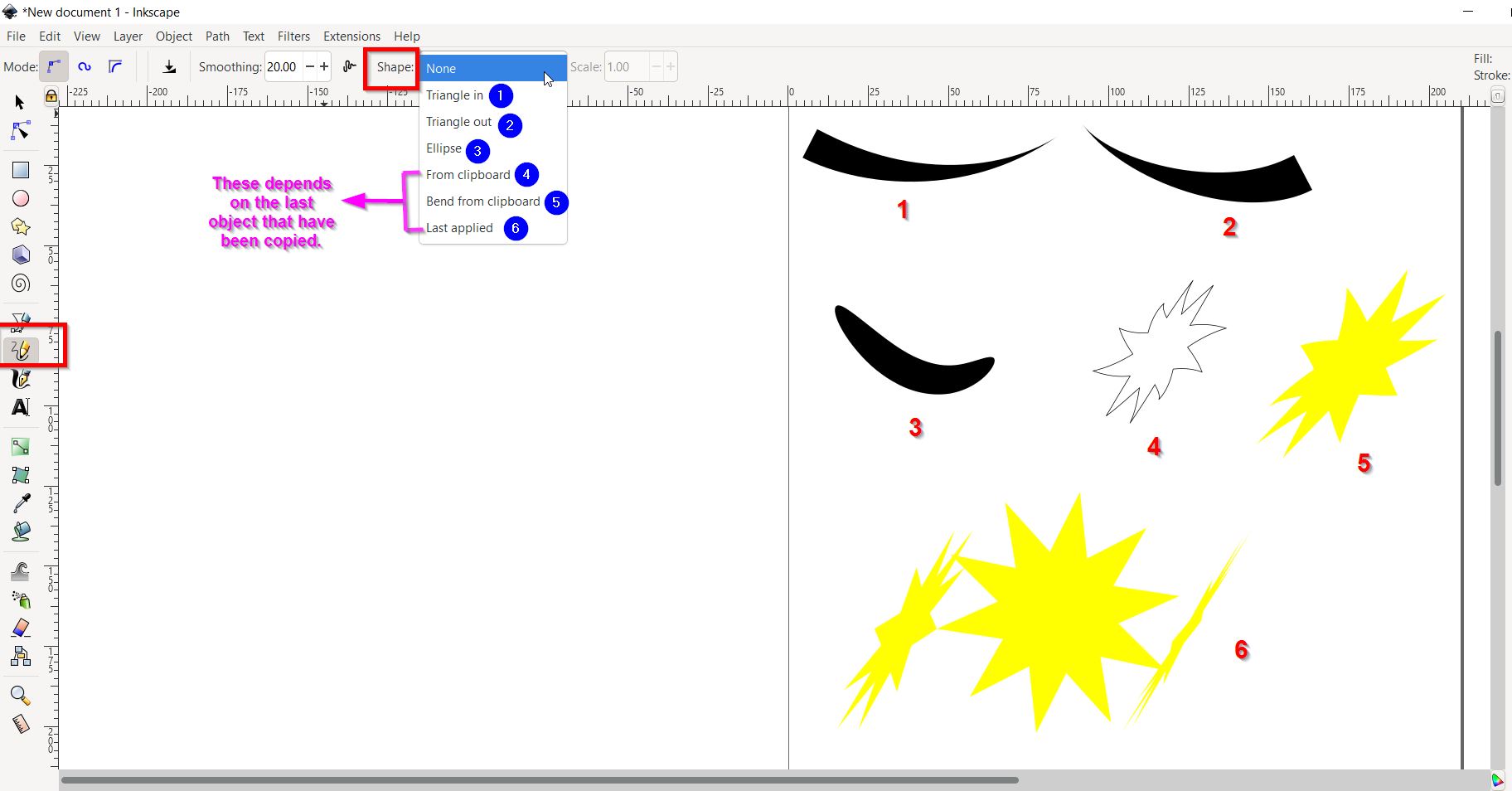
- Freehand Lines:
This tool have alot of different features to be used. For instance, below you will find an example when I drew a line but with changing “shape” type:
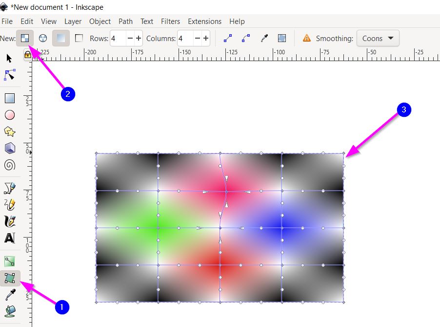
- Mesh Gradient:
Allows you to have much more freedom to change the way the gradient is placed in the sapce. As follows:
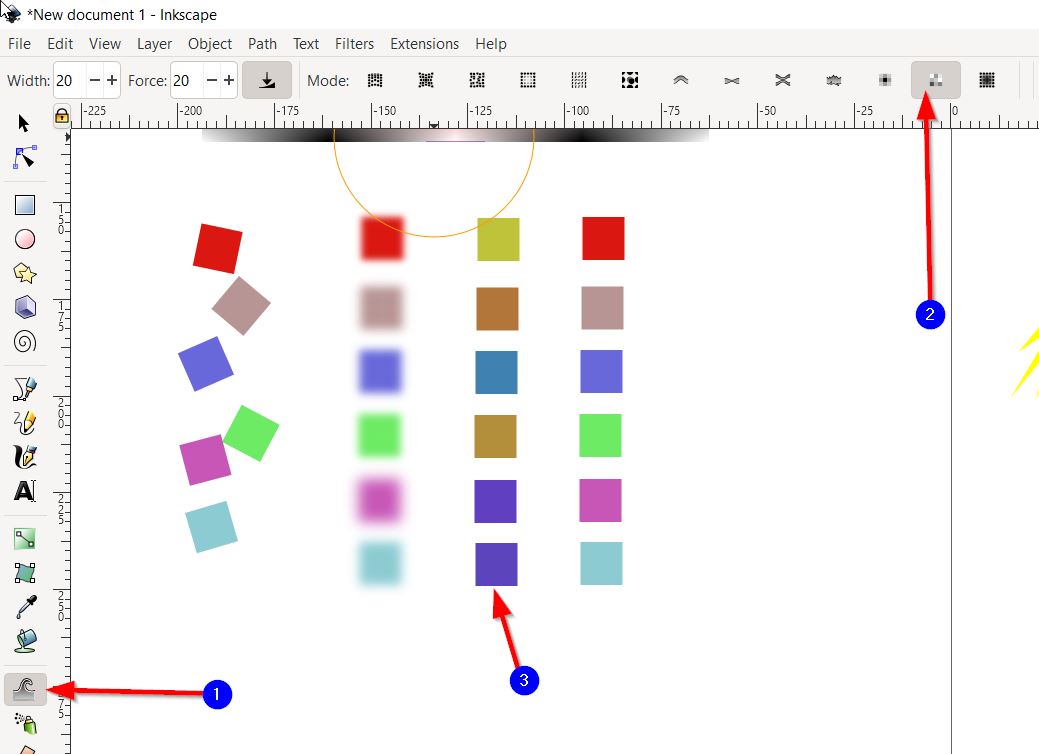
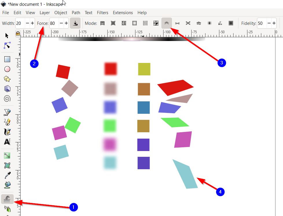
- Tweak Objects and Sculpting:
I have drawn different square, duplicate them, and select each set to try the following Tweak Objects types:
1-Move object any direction:
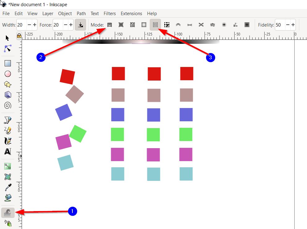
2-Blur Objects:
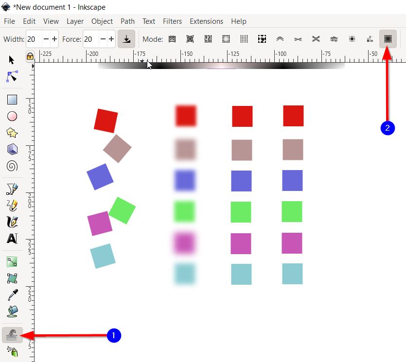
Note : To un-blur select shift + Blur
3-Jetter Color of selected object:
4-Sculpting Object:
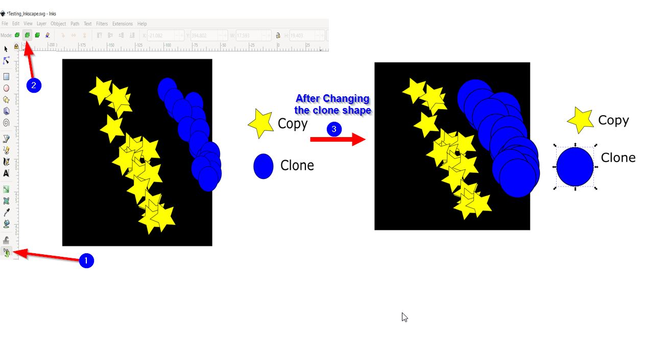
- Spray object by copy and Cloning:
1-Copy:
Note: Here when the original shape changes, the sprayed object will not change.
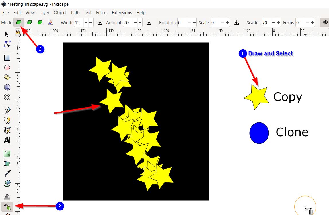
2-Clone:
Note: when the original shape changes, the sprayed object will be also change.
Designing Phase
To further challenge my self and explore the software tools, I have designed a robot by taking some inspiration for the following Tutorial . Thus, below you will find the final design:

Click here to download the design.
FreeCad
FreeCAD is an open-source parametric 3D modeler made primarily to design real-life objects of any size. Parametric modeling allows you to easily modify your design by going back into your model history and changing its parameters. FreeCAD is also multiplatfom (Windows, Mac and Linux), highly customizable and extensible software. It reads and writes to many open file formats such as STEP, IGES, STL, SVG, DXF, OBJ, IFC, DAE and many others, making it possible to seamlessly integrate it into your workflow.FreeCAD equips you with all the right tools for your needs. You get modern Finite Element Analysis (FEA) tools, experimental CFD, dedicated BIM, Geodata or CAM/CNC workbenches, a robot simulation module that allows you to study robot movements and many more features. FreeCAD really is a Swiss Army knife of general-purpose engineering toolkits.
Researching Phase
To learn more about the software I have watched the following Tutorial that is dedicated for beginners.
To learn more information about the software, the following link might be helpful Click to view it.
Then, I kept searching for designs to try them so I can further explore the software. Thus, I have founded the following document that contains multiple of exercises were users can try them to gain more knowledge about the software.
Testing Phase
General Guidance to start your design:
After downloading the app and clicking it to open, the following start screen will appear:
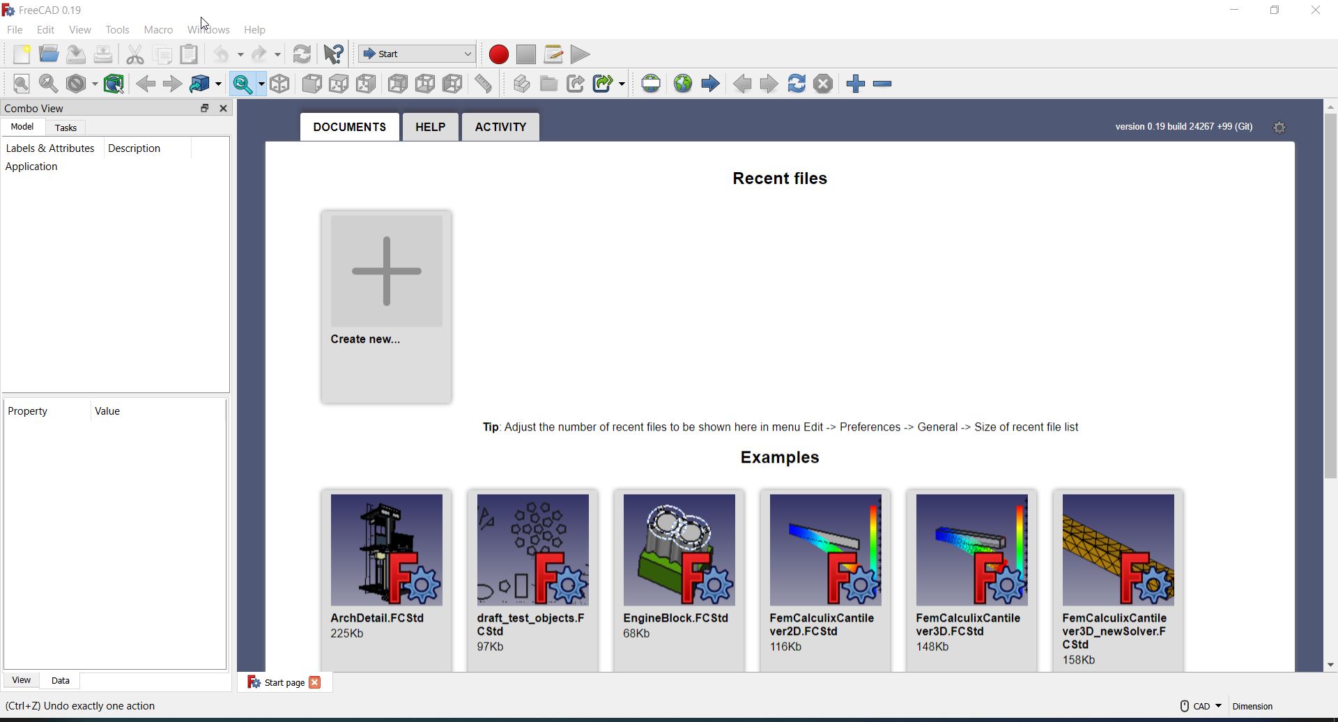
After clicking on “Create new ” button, we will then try the tools available in the software:
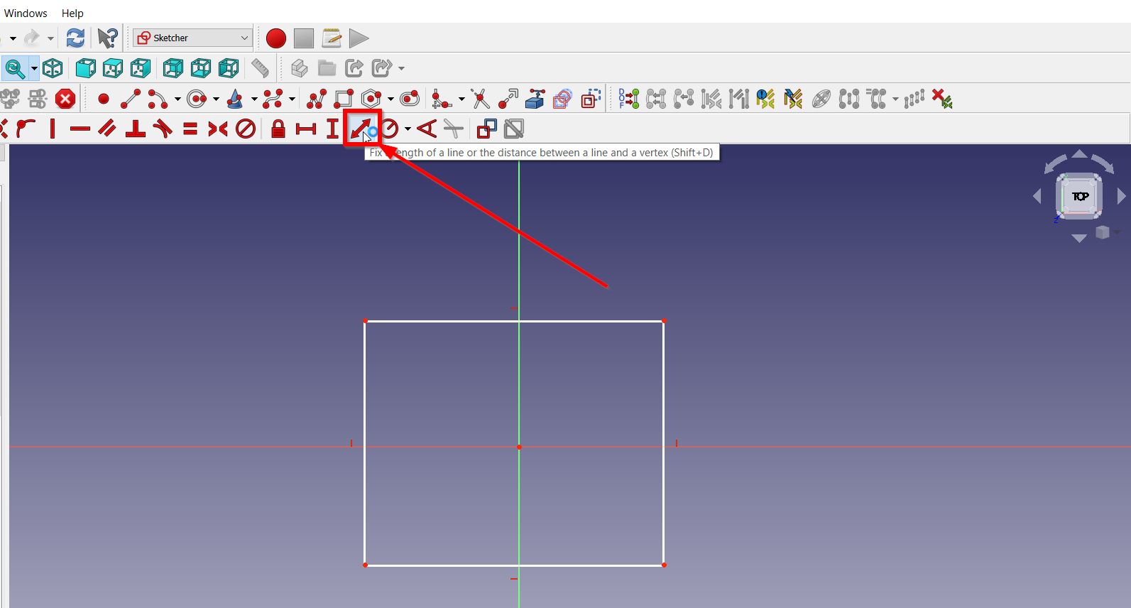
- Setting the length size:
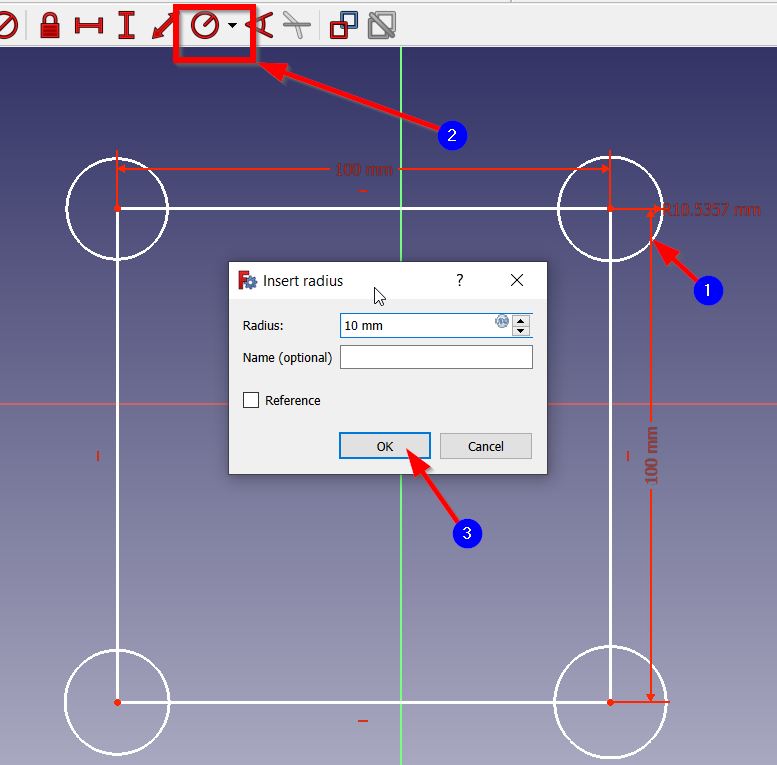
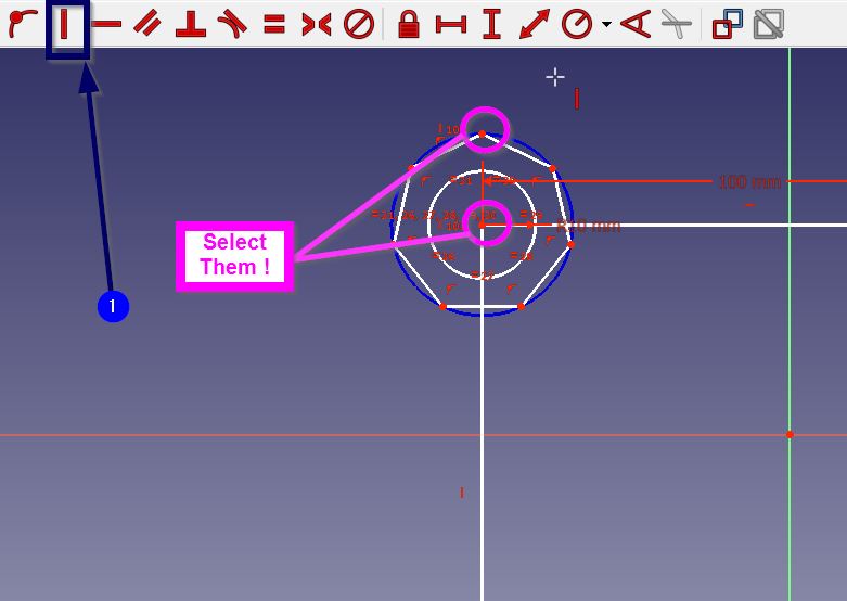
- To change the circle radius use the following tool:
- To create vertical constrain:
- To cut the un-wanted lines:
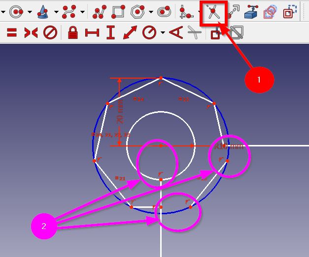
- To join two sides:

- To convert the 2D into 3D, select the object then click “Pad”:
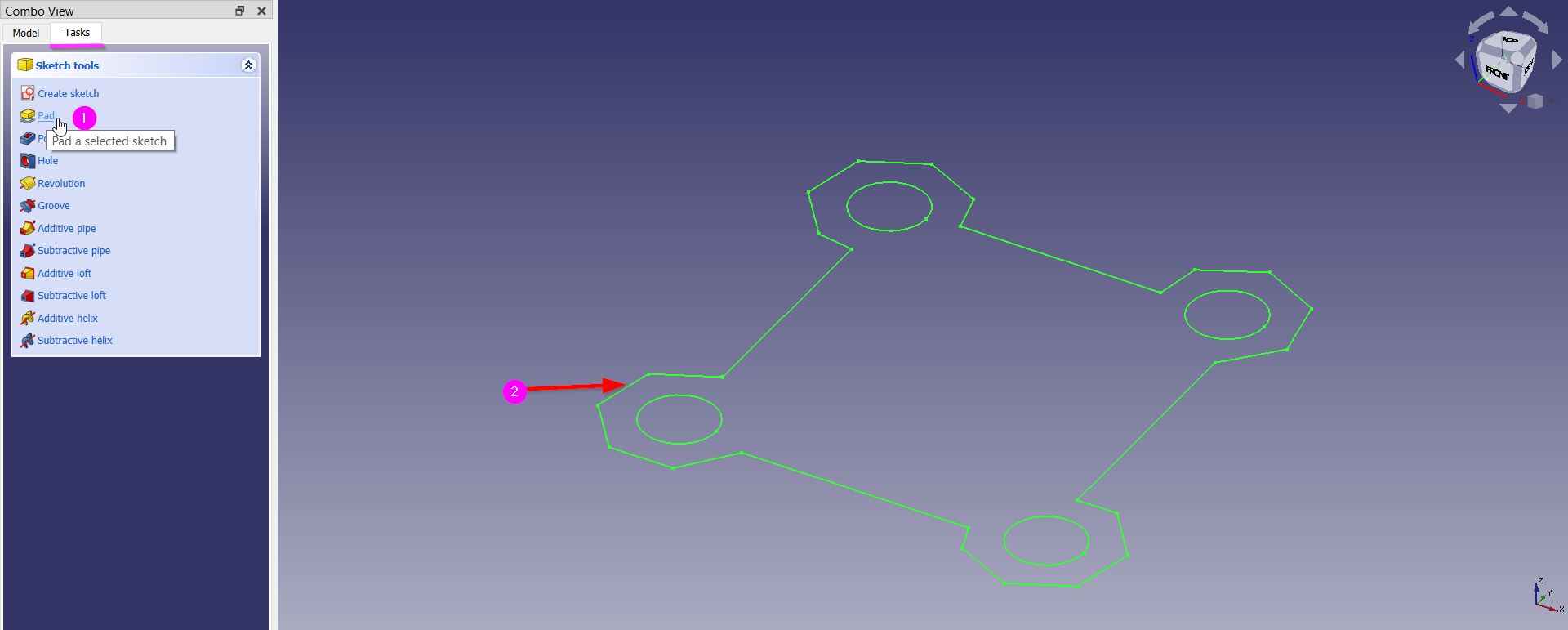
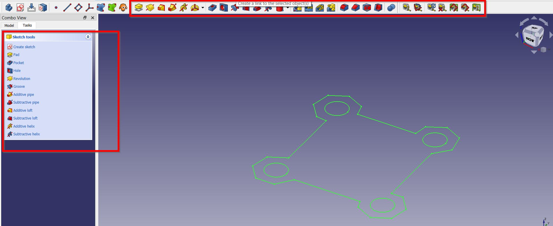
- Then, you will find multiple of 3D Design tools to use:
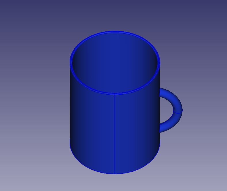
Designing Phase
Thus, to develop my skills and investigate more about the software I sketched a 3D cup using the following Tutorial:
Click here to download the design.
Thank you for reading !