7. Input & Output device
Week Objectives:
As a Individual:
- Measure something: Add a sensor to a microcontroller board and read it.
- Add an output device to a microcontroller board and program it to do something.
- Document your work
Introduction
During this week, we have learnt how to use Adafruit Bluefruit Sense feather and connect inputs and outputs.
What is Input ?
An input is data that is entered into or received by a device. This could include a user pressing a key on a keyboard, reading temperature or distance detection.
What is Output? Is the results of processing the data input to the system/software. It may be printed on LCD Screen, sound, LED light.
Types of sensors:
There are numerous definitions as to what a sensor is but I would like to define a Sensor as an input device which provides an output (signal) with respect to a specific physical quantity (input).
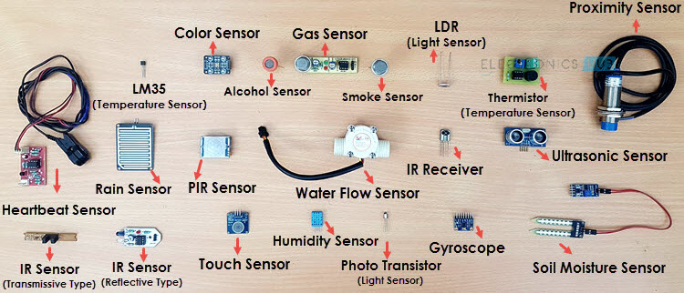
There are several classifications of sensors made by different authors and experts. The following classification of sensors may already be used by an expert in the subject but this is a very simple classification of sensors.
-
In the first classification of the sensors, they are divided in to Active and Passive. Active Sensors are those which require an external excitation signal or a power signal. Whereas Passive Sensors, on the other hand, do not require any external power signal and directly generates output response.
-
The other type of classification is based on the means of detection used in the sensor. Some of the means of detection are Electric, Biological, Chemical, Radioactive etc.
-
The next classification is based on conversion phenomenon i.e., the input and the output. Some of the common conversion phenomena are Photoelectric, Thermoelectric, Electrochemical, Electromagnetic, Thermooptic, etc.
-
The final classification of the sensors are Analog and Digital Sensors. Analog Sensors produce an analog output i.e., a continuous output signal (usually voltage but sometimes other quantities like Resistance etc.) with respect to the quantity being measured. Digital Sensors, in contrast to Analog Sensors, work with discrete or digital data. The data in digital sensors, which is used for conversion and transmission, is digital in nature.
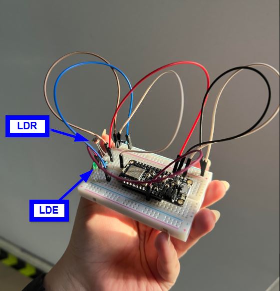
Circuit component Discerption:
Projects
Project 1
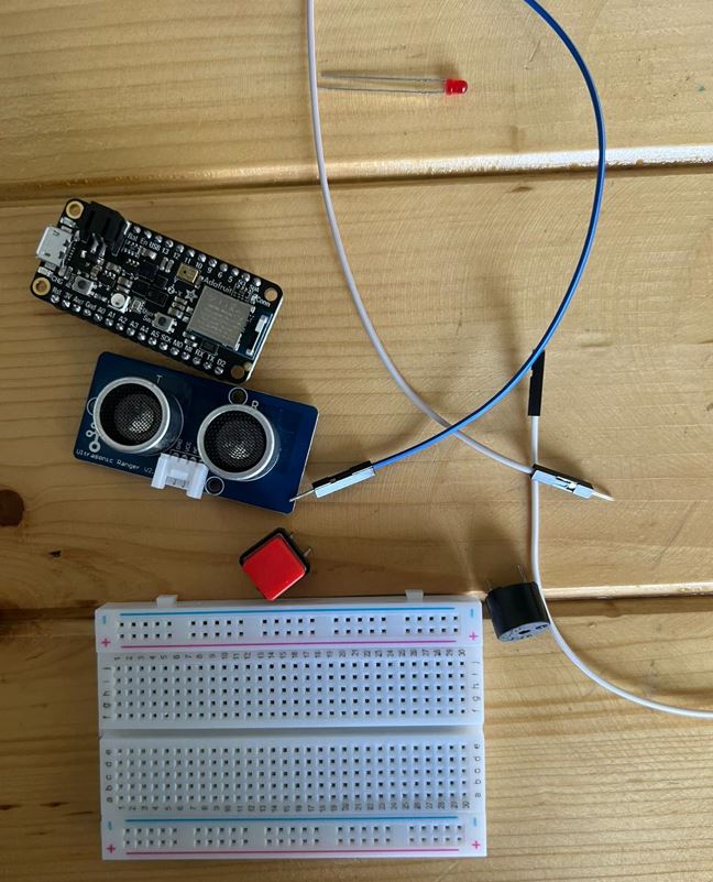
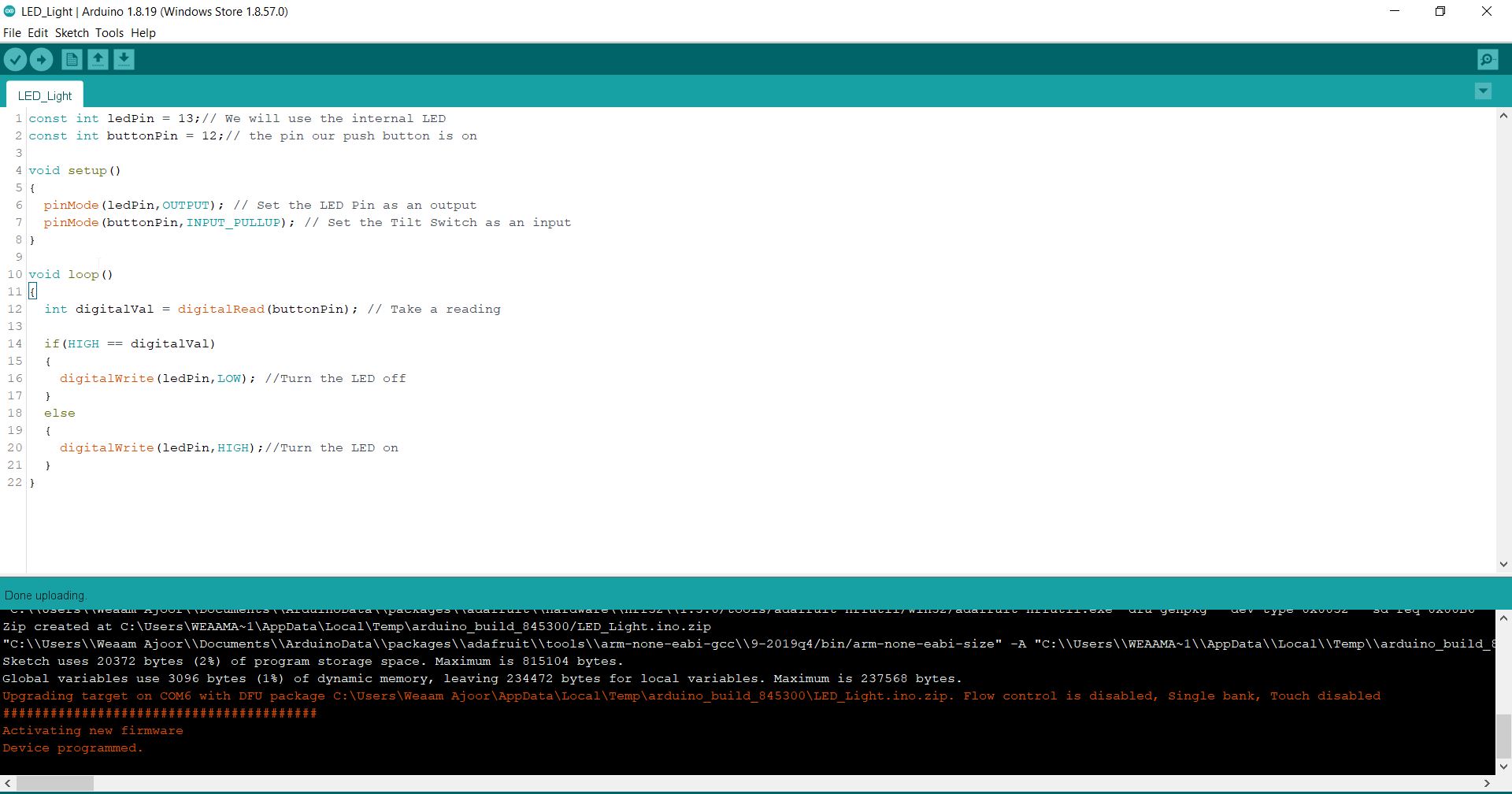
During this project, I did a pushbutton-based light. As follows:
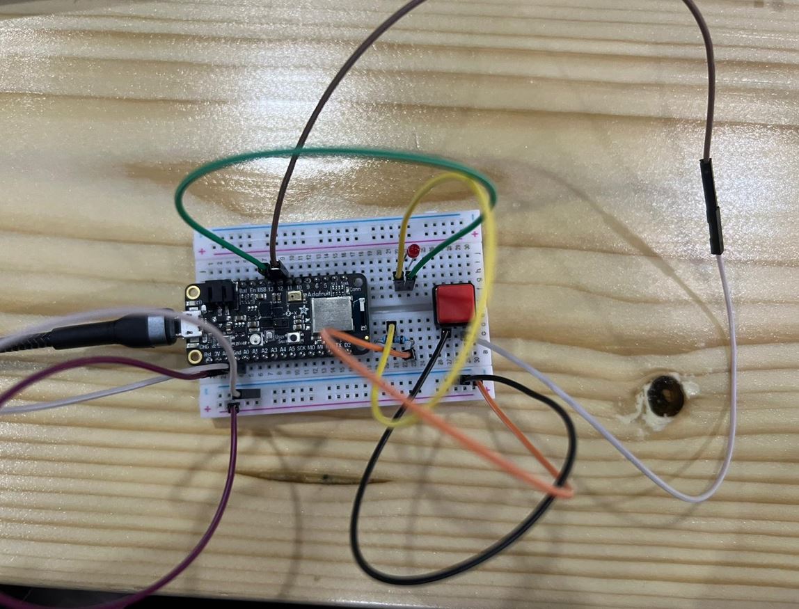
Please find below the code:
  const int ledPin = 13;// We will use the internal LED
  const int buttonPin = 12;// the pin our push button is on
  void setup()
  {
    pinMode(ledPin,OUTPUT); // Set the LED Pin as an output
    pinMode(buttonPin,INPUT_PULLUP); // Set the Tilt Switch as an input
  }
  void loop()
  {
    int digitalVal = digitalRead(buttonPin); // Take a reading

    if(HIGH == digitalVal)
    {
      digitalWrite(ledPin,LOW); //Turn the LED off
    }
    else
    {
      digitalWrite(ledPin,HIGH);//Turn the LED on
    }}
It has been successfully complied !
Hero Video:
Project 2
During this project, I tried to do a street light. As follows:
I got insights from the following tutorial:
The following the circuit accomplished:
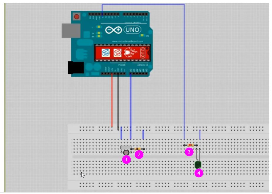
Connections: 1 - LRD 2- Resistor 220 ohm 3- Resistor 10K ohm 4- LED
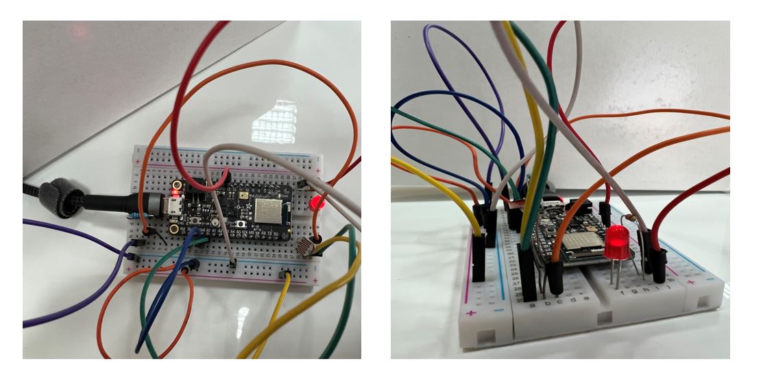
Final circuit after connecting all the components:
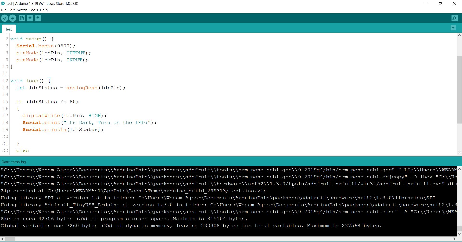
Please find below the code:
const int ledPin = 13;
const int ldrPin = A0;
#include <SPI.h>


void setup() {
  Serial.begin(9600);
  pinMode(ledPin, OUTPUT);
  pinMode(ldrPin, INPUT);
}

void loop() {
  int ldrStatus = analogRead(ldrPin);

  if (ldrStatus <= 80)
  {
    digitalWrite(ledPin, HIGH);
    Serial.print("Its Dark, Turn on the LED:");
    Serial.println(ldrStatus);

  }
  else
  {
    digitalWrite(ledPin, LOW);
    Serial.print("Its Bright, Turn off the LED:");
    Serial.println(ldrStatus);
  }

}
It has been successfully complied !
Hero Video:
Challenge Time !
Our instructor have asked us to do one of the following tasks from below:
EASY MODE: Use the one of the sensors on the Adafruit & try to program to display its results in the serial monitor + to be represented by an LED &/or Buzzer
MEDIUM MODE: Use a variable resistor as an input to to control either the speed or the direction of the servo motor.
HARD MODE: Try to create a small automated farming system using the light sensor & the servor motor. Where it’s according to sun day the plant start be filling by the water.
EXTREME MODE: Create a cooling system using a fan, variable resistor, Temperature sensor & an LCD. The idea is to control the fan automatic & manually. You can adjust the fan coolness automatically using the temperature sensor to increase or decrease the fan rotation and display its on the LCD. Or switching the to manual mode where you rotate the variable resistor according to how fast you want the fan to go and it should be display on the LCD screen.
I have chosen the easy mode, were I went on to try color sensor on the Adafruit, try to program it, and display its results in the serial monitor.
As we researched on week 04, the Adafruit have an embedded color sensor here:
I found and followed this tutorial to test the light sensor:
Steps:
1- I have downloaded the library targeted:
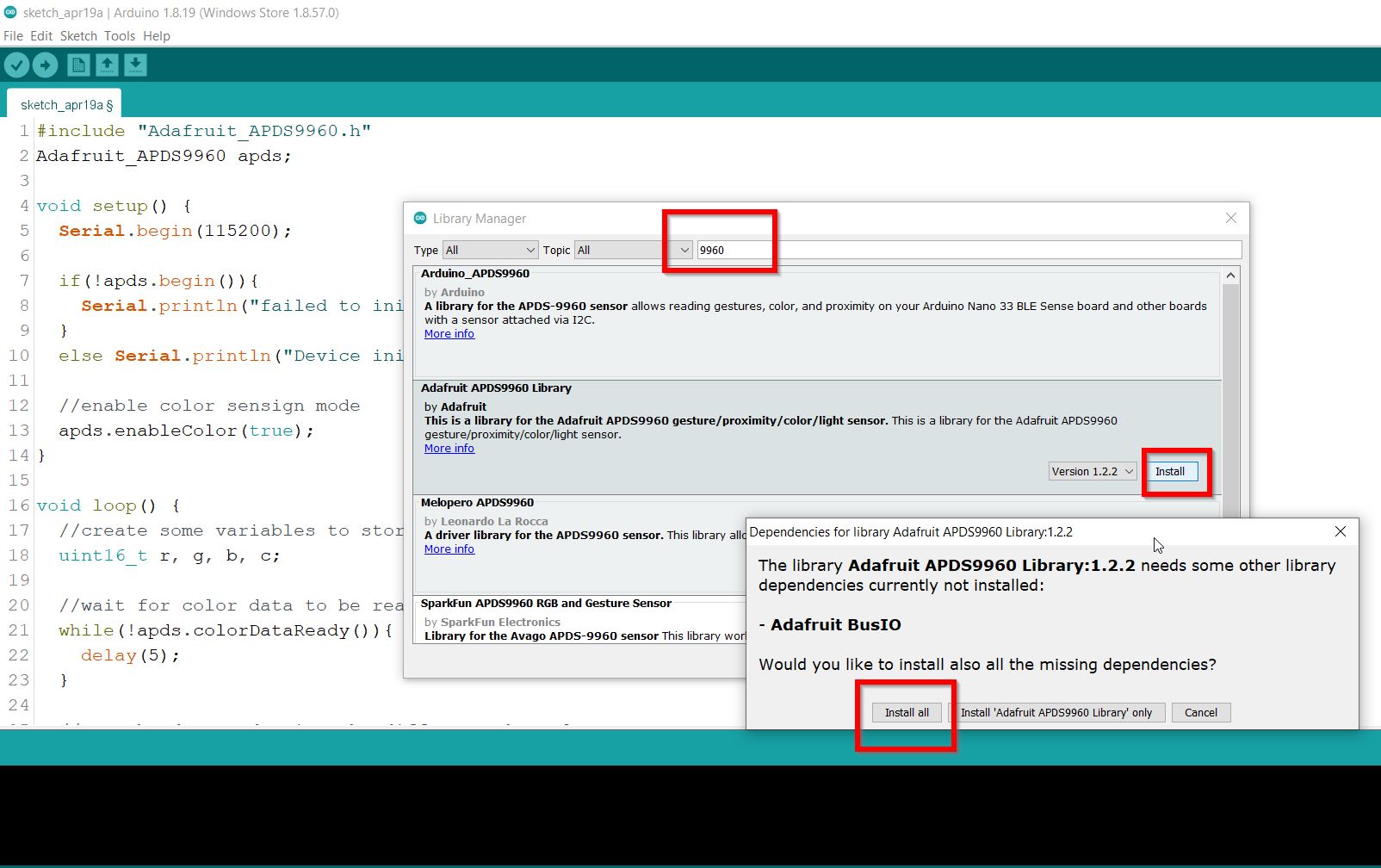
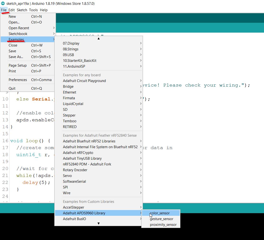
2- Throughout this tutorial I have noticed that their was example to test the color sensor here:
From the File menu of the Arduino IDE, select Examples –> Adafruit APDX9960 Library –> color_sensor.
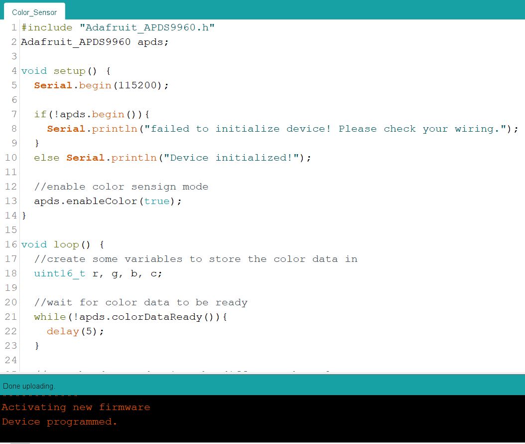
Here you may find the code:
Please find below the code:
#include "Adafruit_APDS9960.h"
Adafruit_APDS9960 apds;

void setup() {
  Serial.begin(115200);

  if(!apds.begin()){
    Serial.println("failed to initialize device! Please check your wiring.");
  }
  else Serial.println("Device initialized!");

  //enable color sensign mode
  apds.enableColor(true);
}

void loop() {
  //create some variables to store the color data in
  uint16_t r, g, b, c;

  //wait for color data to be ready
  while(!apds.colorDataReady()){
    delay(5);
  }

  //get the data and print the different channels
  apds.getColorData(&r, &g, &b, &c);
  Serial.print("red: ");
  Serial.print(r);

  Serial.print(" green: ");
  Serial.print(g);

  Serial.print(" blue: ");
  Serial.print(b);

  Serial.print(" clear: ");
  Serial.println(c);
  Serial.println();

  delay(500);
}
3- I have connected the microcontroller and uploaded the code. It has been successfully complied as shown below !
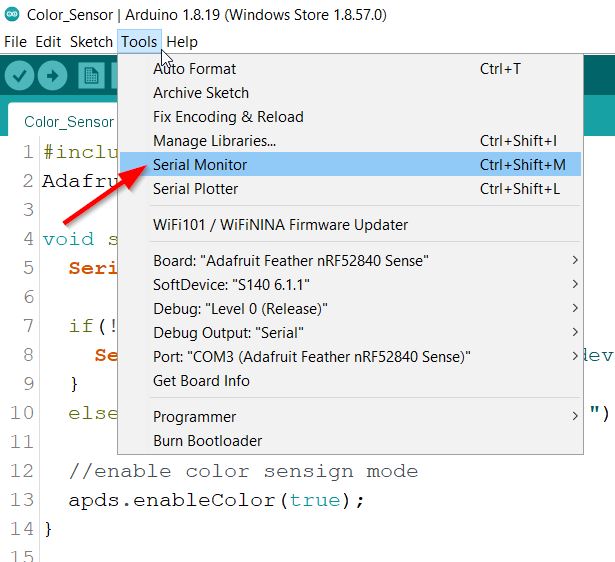
4- I have then opened the serial monitor to capture the output from the following buttons:
5- Finally, I applied light a light and here you can find the output:
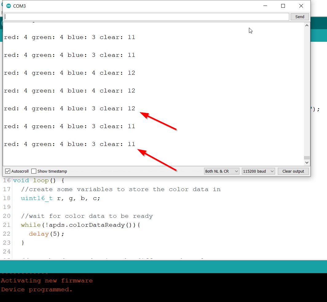
This the outputs before applying the light:
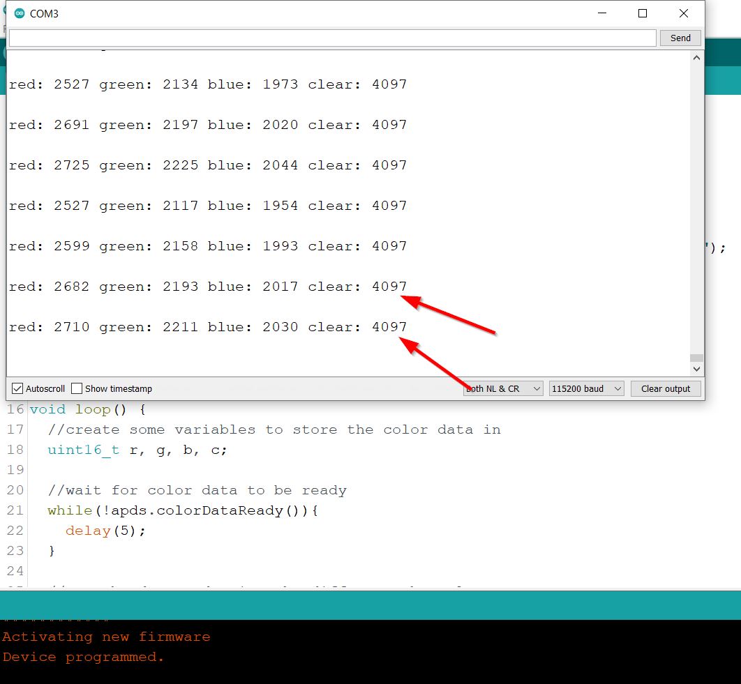
This is the result after applying clear light:
Errors & Solutions
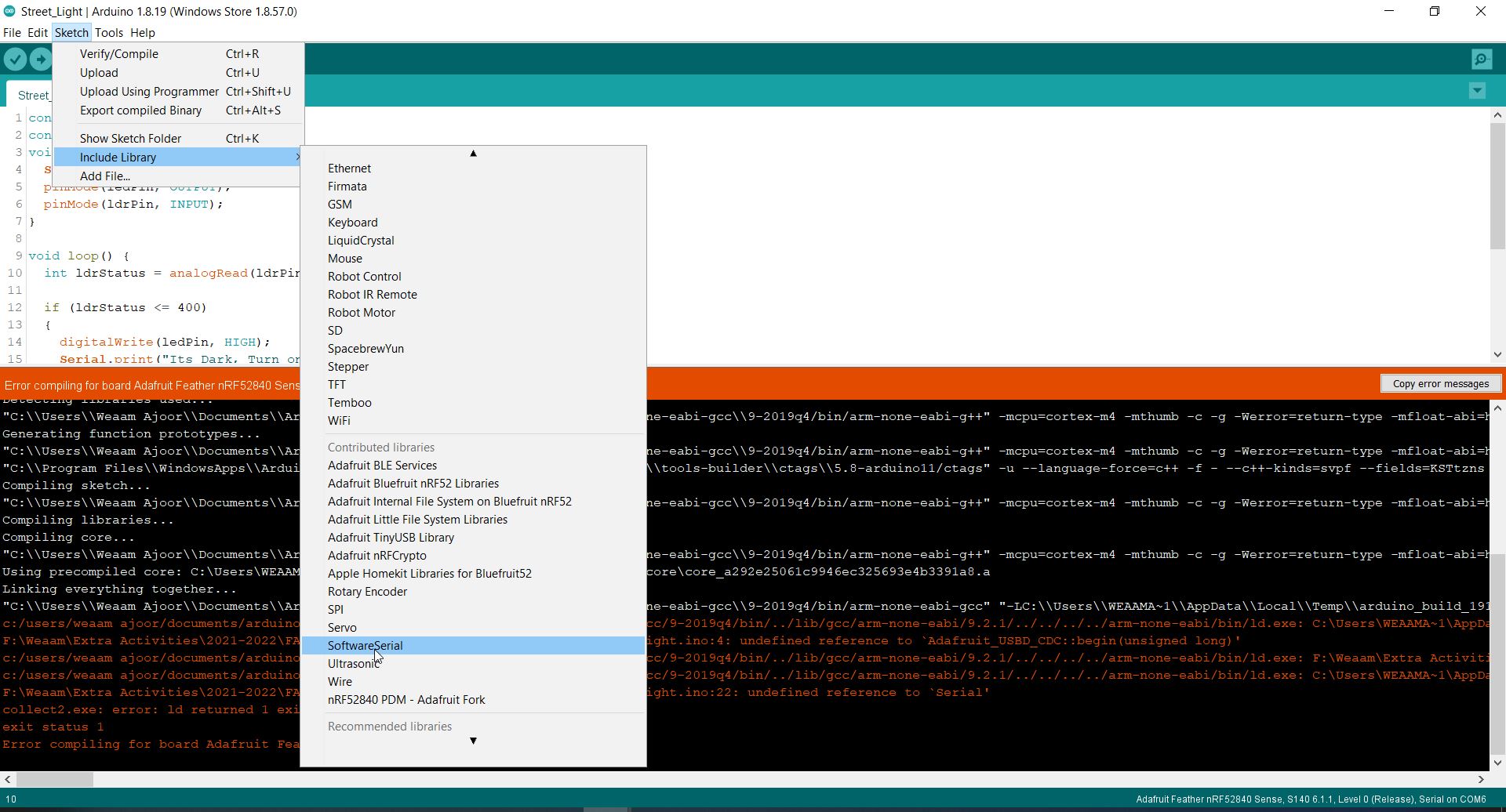
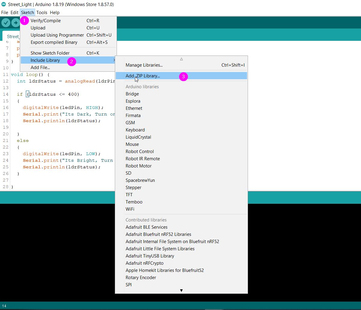
Error 1
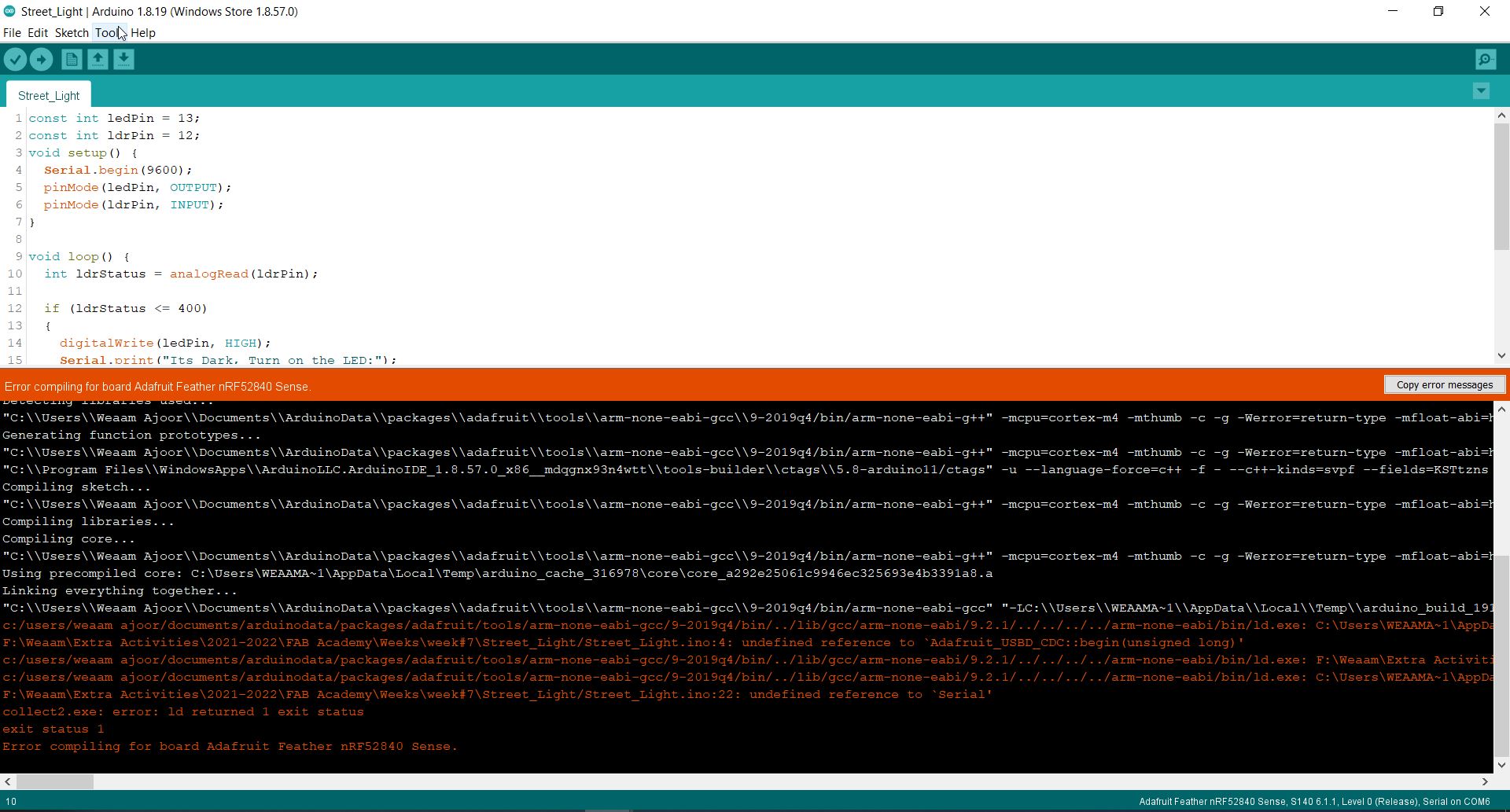
I have overcome the error by selecting Tools > Manage Libraries > SoftwareSerial:
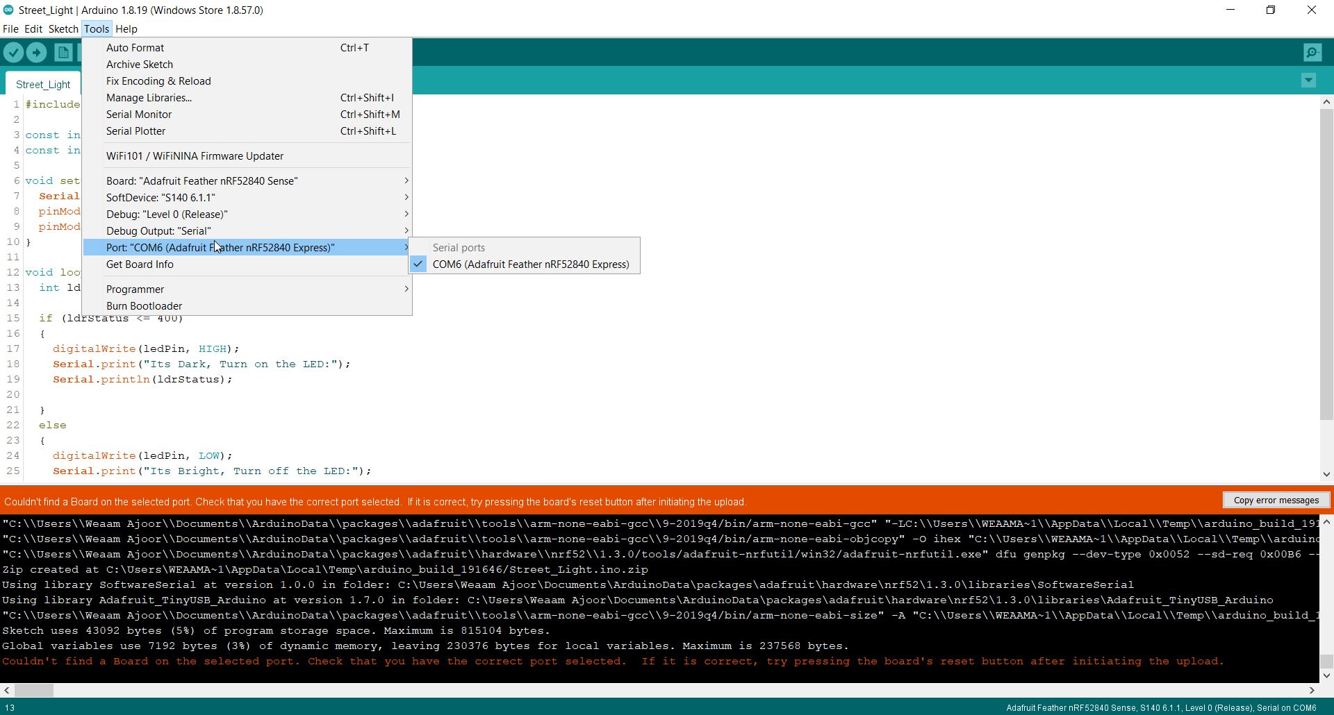
Error 2
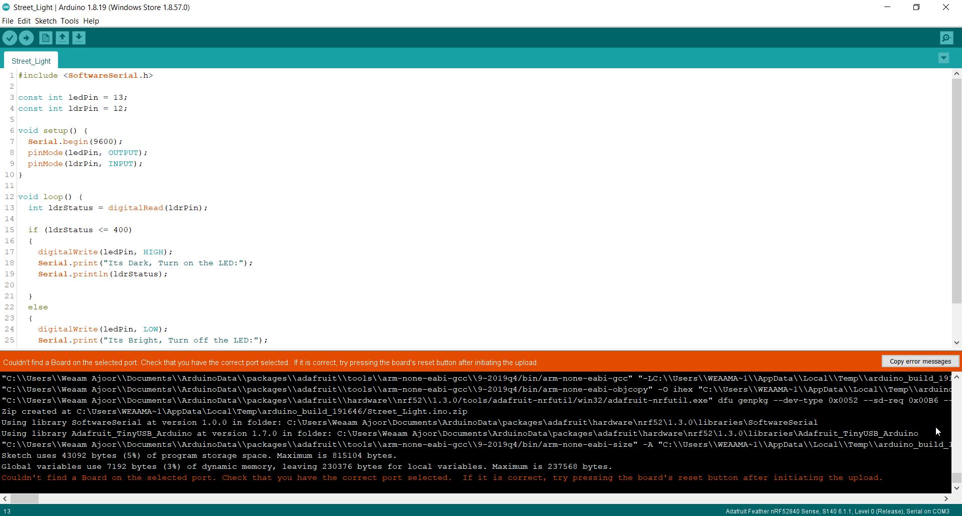
I have overcome the error by:
- Reconnecting the USB Cable
- Press two times the re-start buttons
- Click on Tools > Port COM6 > COM6 (Adafruit Feather nRF52840 Express).
Error 3
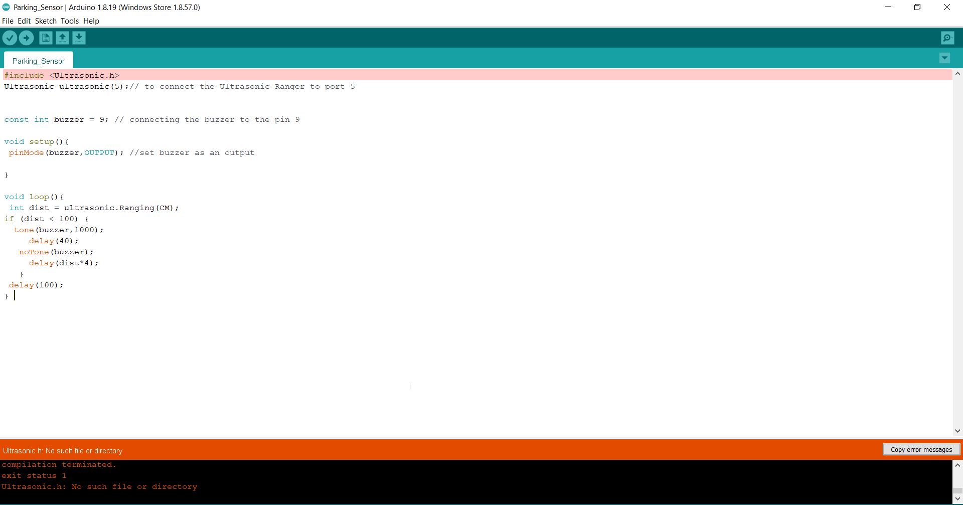
I have overcome this error I have downloaded the Ultrasonic library and have embedded it to the software. As follows:
Resources
Thank you for reading !