3. Computer controlled cutting
Week Objectives:
As a Group:
- Characterize your laser cutter’s focus, power, speed, rate, kerf, and joint clearance
- Document your work (individually or in group)
As an Individual:
-
Design, lasercut, and document a parametric press-fit construction kit, which can be assembled in multiple ways. Account for the lasercutter kerf.
-
Cut something on the vinyl cutter
Group Assignment
Please refer to my collogue group work page:
Individual Assignment
Vinyl Cutting
What is a Vinyl Cutting ?
Vinyl cutting is the act of creating a design in a software program then sending that design through to a vinyl cutter, which will cut out your design using a blade on sheets of vinyl. Once the vinyl cutter has done its work, you then need to weed the cut vinyl sheets — removing all the waste vinyl from the paper backed sheet — and transfer the final design onto wherever you want it to go as your laptop, car, walls, cards, scrapbooks, etc…
Testing Phase
Cricut Vinyl Cutter: is an electronic cutting machine that can cut all sorts of designs from materials like paper, vinyl, card stock, and iron-on transfers. Some Cricut machines can even cut leather and wood! You can use the Cricut to cut just about anything you would typically cut with scissors or an X-acto knife.
The instructor have also further introduce us to the “Cricut Vinyl Cutter” :
-
The cutter can cut only in the x-axis. Whereas, the Y-axis is used to drag the material as paper to the machine.
-
The cutter can cut to a maximum of 2mm of depth.
-
A sticky mate needs to be placed below the material to stabilize the material in one place. Therefore, we also sometime may use tape to make sure that the material is in a fixed location.
-
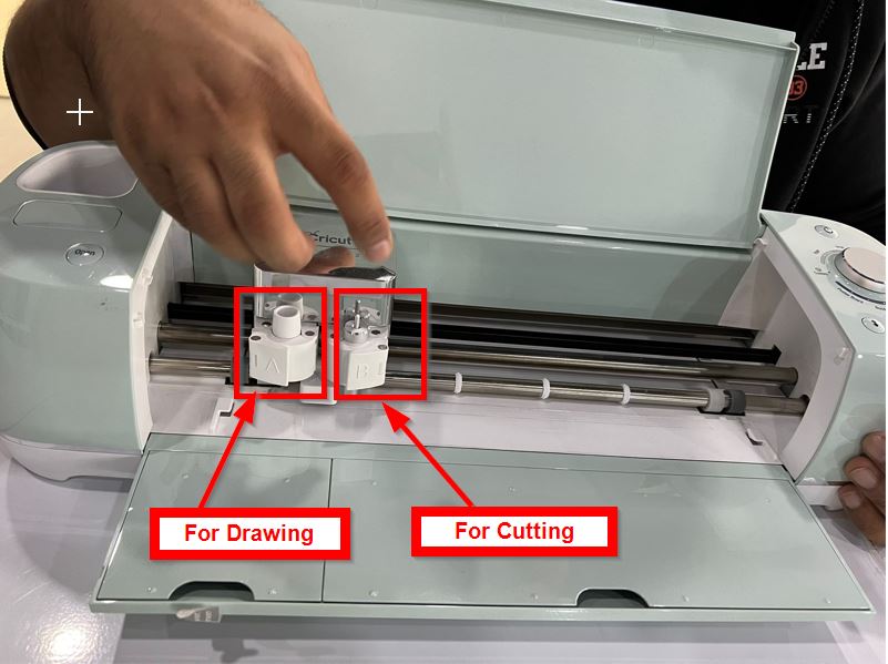
The cutter can preform two main functions (A and B). A is a blade for drawing where as B is blade for cutting. As follows:
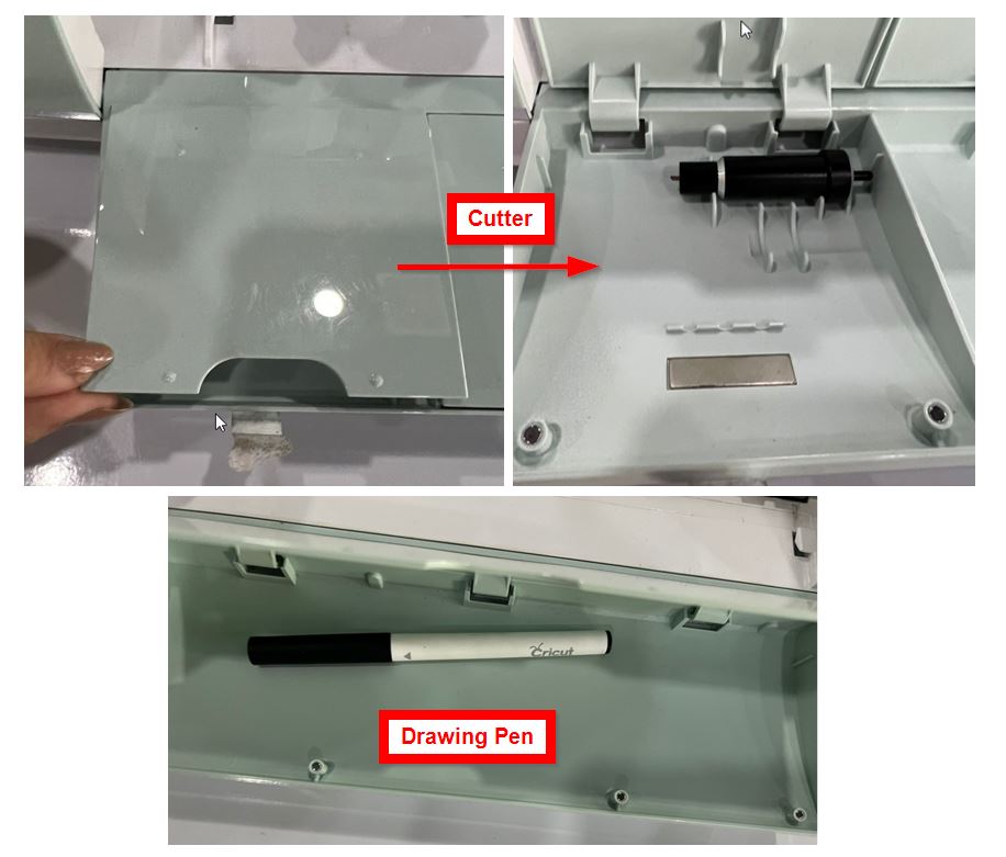
You can find the pen and cutter tool in the drawer as shown below:
- Other Settings:
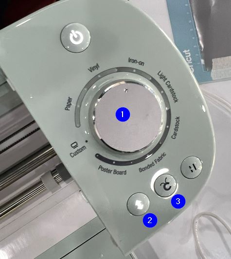
“1” is used to select the material that will be used.
“2” to insert the mate with the material.
“3” to start the cutting process.
Testing time !
To further enhance our knowledge, the instructor did with us a simple test to cut a small design. As follows:
Note: I will explain the full process taught below when I cut my own design.
Design Cutting Phase
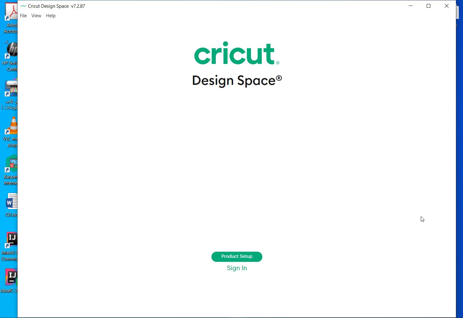
- The first step is to download Cricut Design Space Application to create and edit our designs.
After the installing the application, I was requested to create an account to easily retrieve my designs in future:
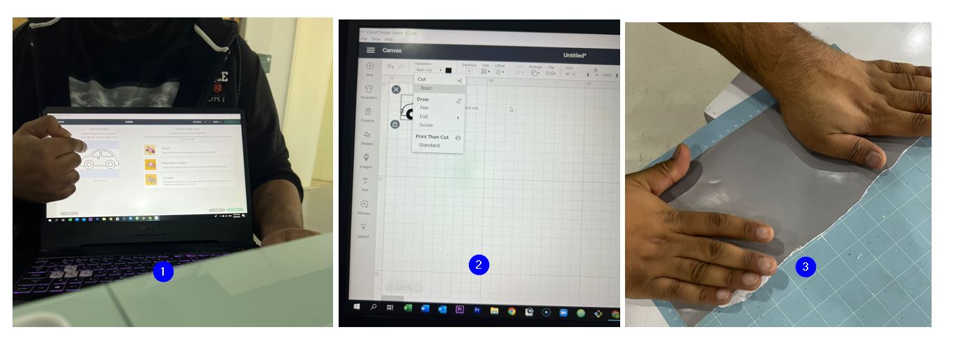
- After selecting “New project, any image available or design created (for example, using cuttel software) is uploaded:

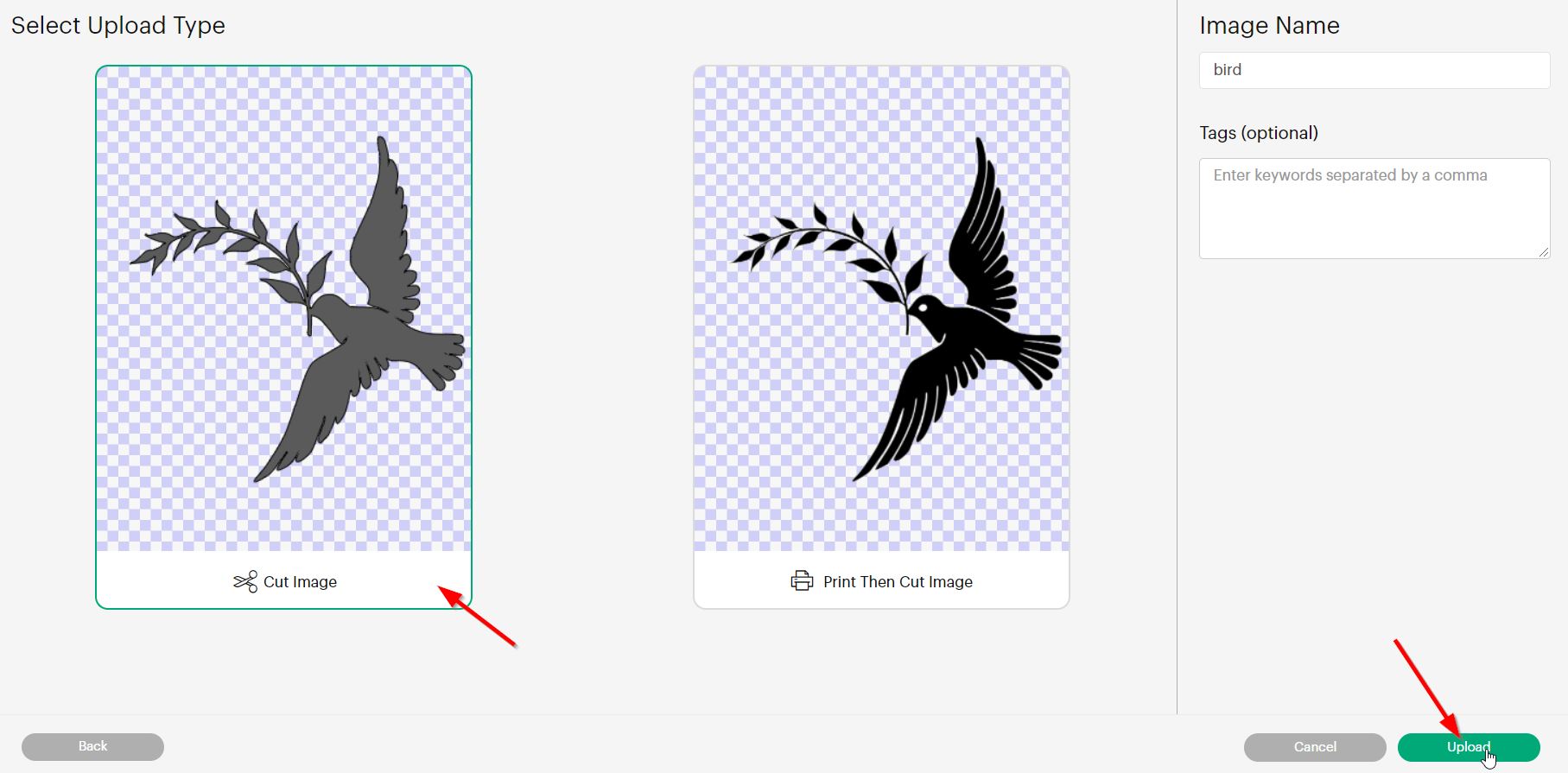
- The image type is then selected and “Continue” button was pressed, as follows:
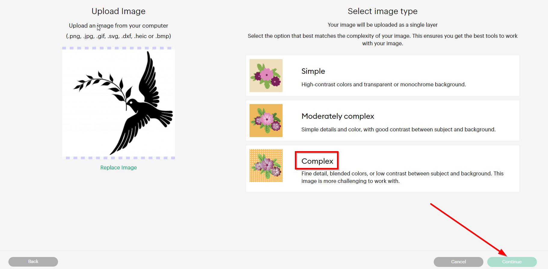
Note: The Image types refers to how detailed your image would be. Also, it is preferred to select “complex” because the application would display for you more tools/features.
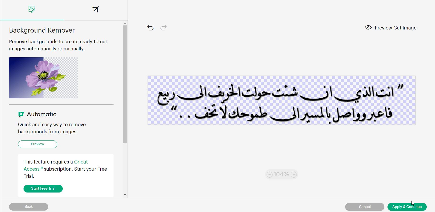
- The image’s background was removed and “Apply & Continue” button as selected:
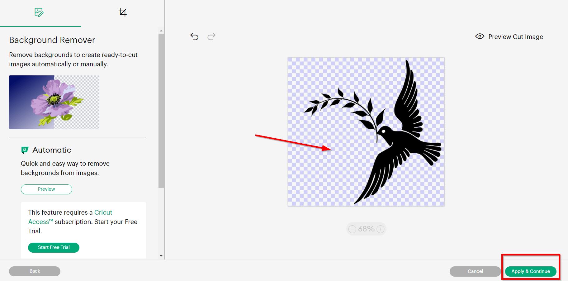
- Select “cut image” and then uploade the image:
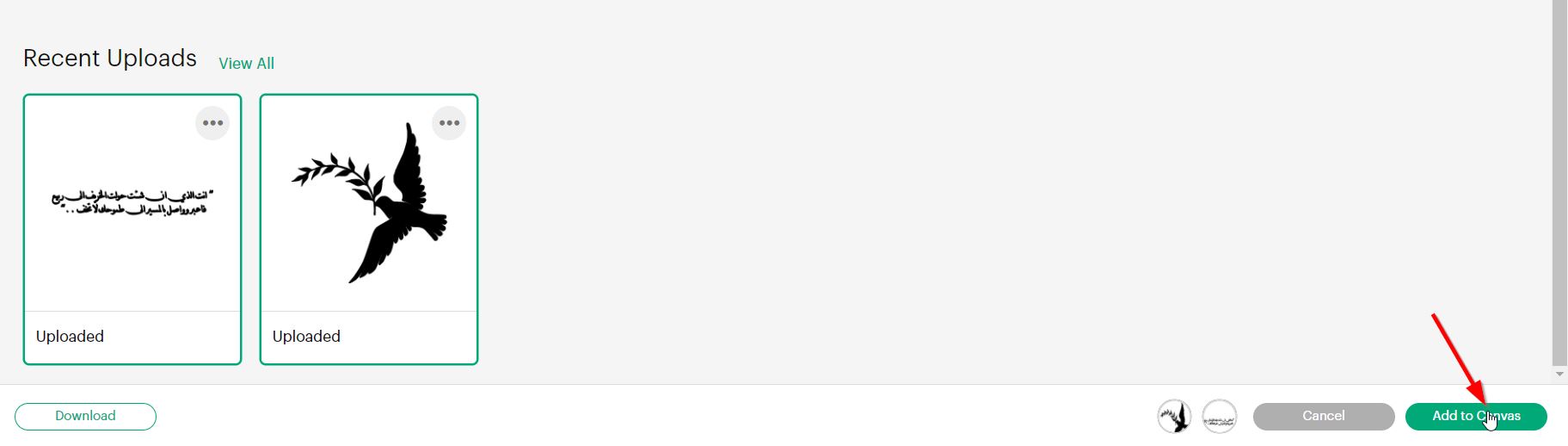
- Then all the process above was repeated to uploaded another image :
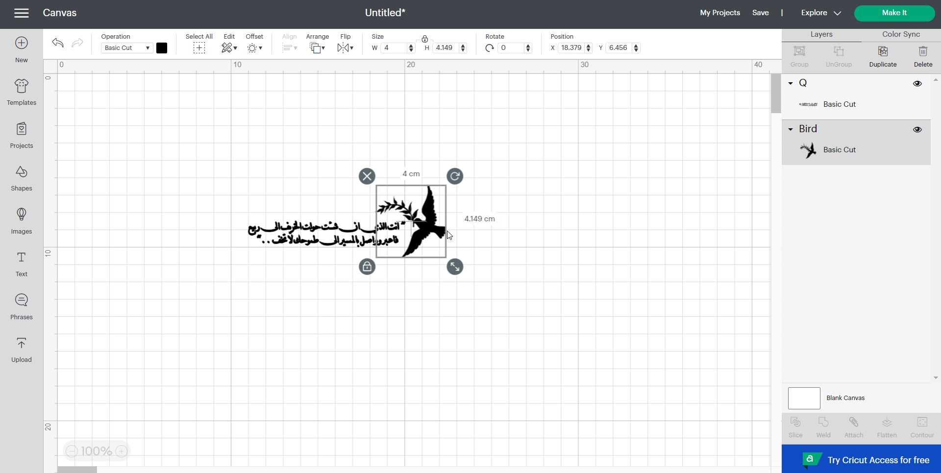
- Both images have then been added to the canvas:
- I went then and edit the images sizes:
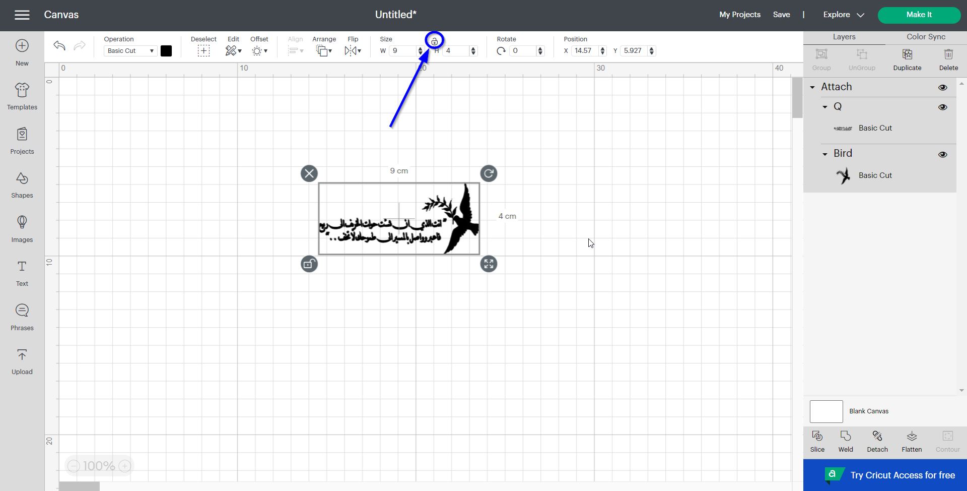
- Both images where grouped using “”Attach”” button at the right-hand side of the screen. Then, the size was unlock to easily set the design sizes. as shown below:
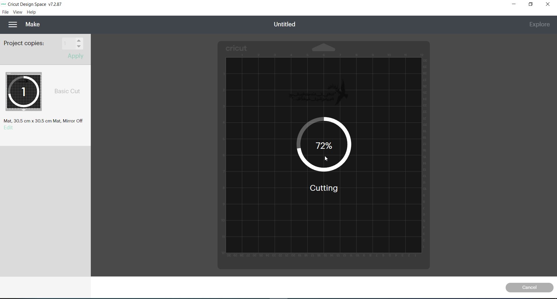
- To start the cutting process, select “Make it” > “Basic Cut” > “continue” button:
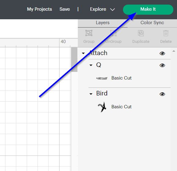
-
Make sure then to connect the PC with the Vinyl machine using a USB cable.
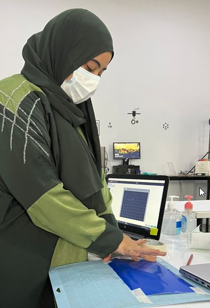
-
A piece of sticker sheet was then placed and tapped it to the mate.
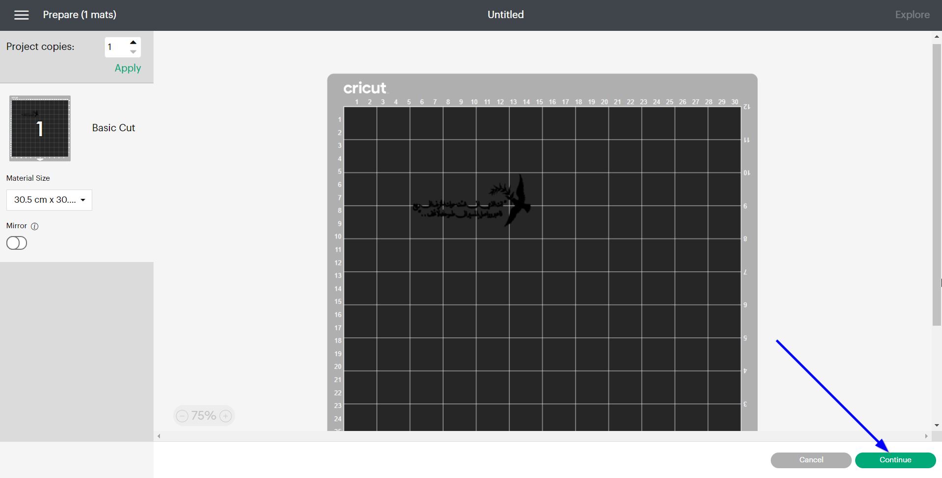
- Then, the following buttons were clicked:
Note: make sure when you inset the mate, to hold it in the air and press the push button.
- The application will display the following screen:
- Once the cutting is done you may use transparent sticker sheet to easily transport the sticker to the desired location, as follows:
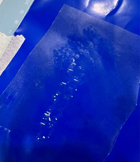
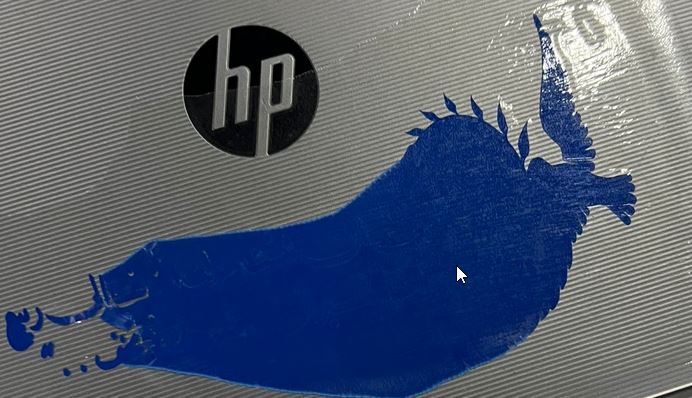
My first trial have failed as shown below because the design was to small:
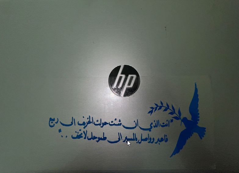
- Thus, I have enlarge the design and cut it again.

Hero shot
Design files
Laser Cutting
Introduction
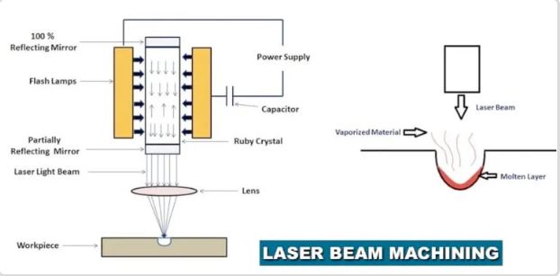
Laser beam machining is a form of the machining process in which laser beams are used for the Machinings of metal and non-metallic materials. In this process, laser beams of high energy are created to strike the workpiece (the object in which the operation is to be carried out), the thermal energy of the lasers is transferred to the surface of the workpiece. The heat generated on the surface heats, melts and vaporizes the material by workpiece.Light amplification by stimulated emission of radiation called Laser.
Advantages of Laser Beam Machining: - It can be focused on very small diameters. - It is capable of producing a very accurately placed hole. - Laser beam machinings have the ability to cut or engrave almost all types of materials when conventional machining processes fail to cut or engrave any material. - There is no physical contact between the equipment and the workpiece. - This helps reduce oxidation of the W / P surface and keep it free of melting of the vaporized material.
Disadvantages of Laser Beam Machining: - It is limited to thin sheets. - The life of the flash lamp is short. - It is not possible to remove a large number of metals. - The machined holes are not round and straight. - Not able to drill too deep holes. - It’s having a high cost. - A very low rate of metal-removing.
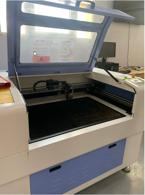
As a group assignment, our instructor have provided us with the enough knowledge on how to use and cut our designs using the laser cutter machine. Below as some important notes I have documented, and for more details you may refer to the link attached in “Group Assignment” section.
Safety Guidelines
Generally:
-
Always keep the machine door closed.
-
Keep your hands away from the machine, because it might burn form the laser beam.
-
Before cutting, “frame” your design to have a preview were the machine will cut.
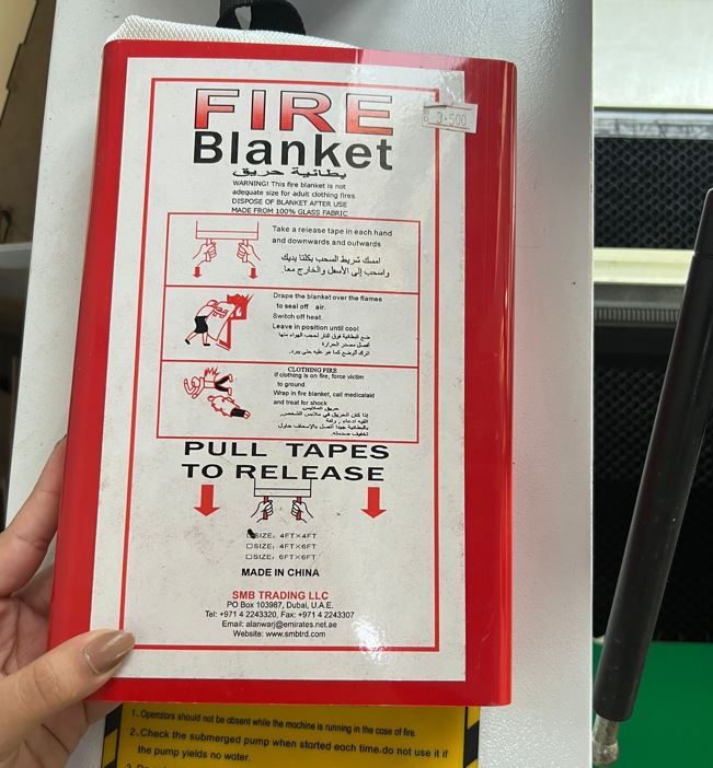
In case of fire:
- A fire Blanket may be used to extinguish the fire.
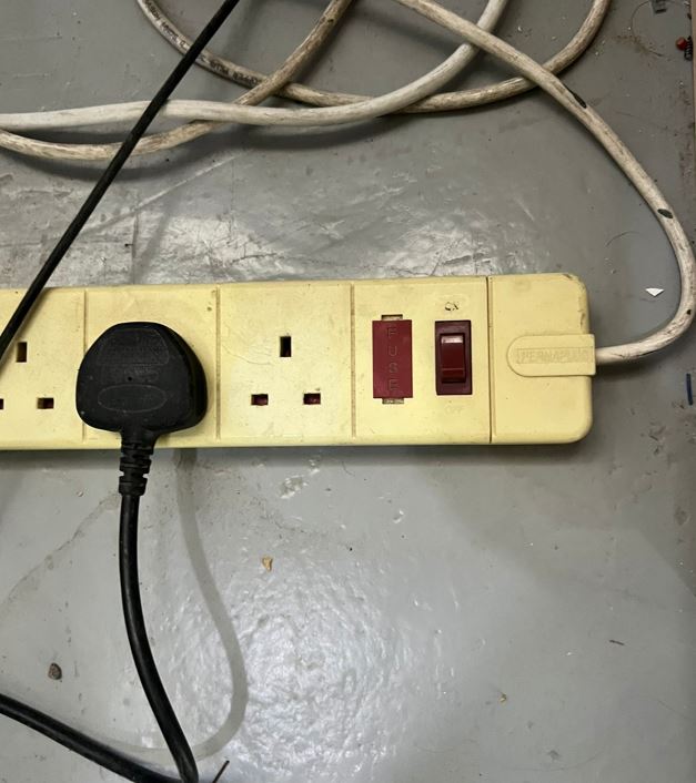
- The extension wire can also be cut off, to avoid spread of fire.
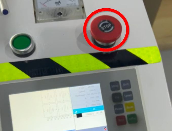
- The machine’s red button is pushed to stop the cutting process.
Testing Phase
To try the machine, we have accomplished the following steps:
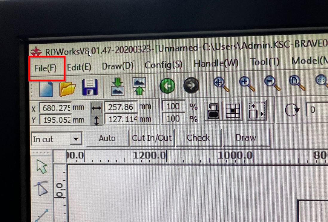
- First we have uploaded the testing file by clicking on file>import>select the desired file:
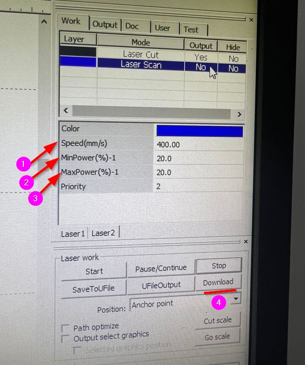
- Place the design in the right positioning, and then set the “Power” & “Speed”. Finally, click the “Upload” button:
- Mahine Interface:
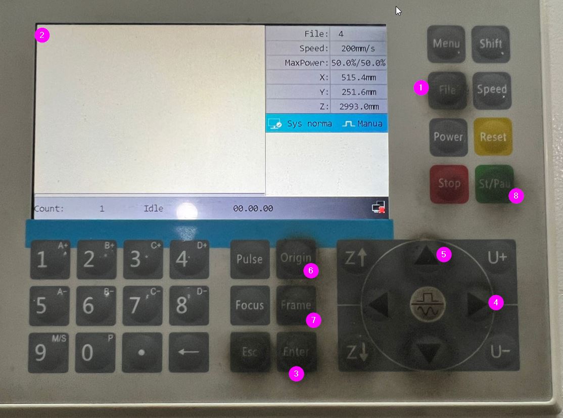
Key Buttons:
1- FILES: After uploading to the machie we select the requested file from this section, and then the “Enter” button is pressed.
2- AXIS: We can move the machine using the y,x, & z-axis buttons, this helps us to select our orign point before starting the cutting process.
3- ORIGIN: This button is pressed to set the machine in intial point to start cutting; this helps us to avoid the laser pointer going out of the matboard.
4- FRAME: This button helps us to have a preview on the size of the shape, checking if the shape fits the material to be cutted, and examine the cutting positioning.
5- START: this button start the cutting process.
- This was the final result, but we kept on cutting different times to determine the best “Power” & “Speed” values in which the material donot burn and to find the “Best-Fit”.
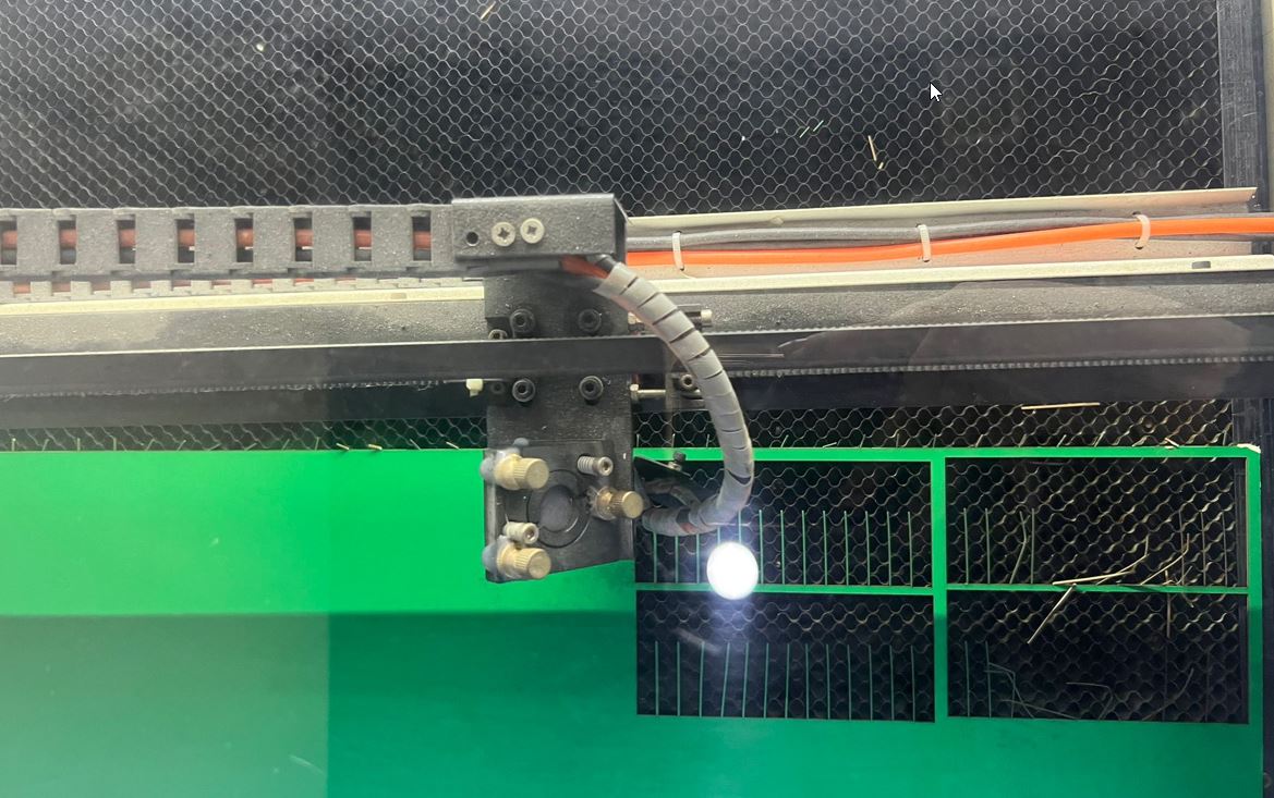
Thus, we concluded that the best set for Matboard is:
“Power” = 35 “Speed” = 35
Parametric Designing Process
Squares Design
I would like to highlight that for this design I repeat it six times because I was facing couple of issues with the software and I changed the design twice. I learnt a lot of skills through these trials. Thus, I will present to you here the final sketch design steps. Using FreeCAD Software, I have accomplished the following steps:
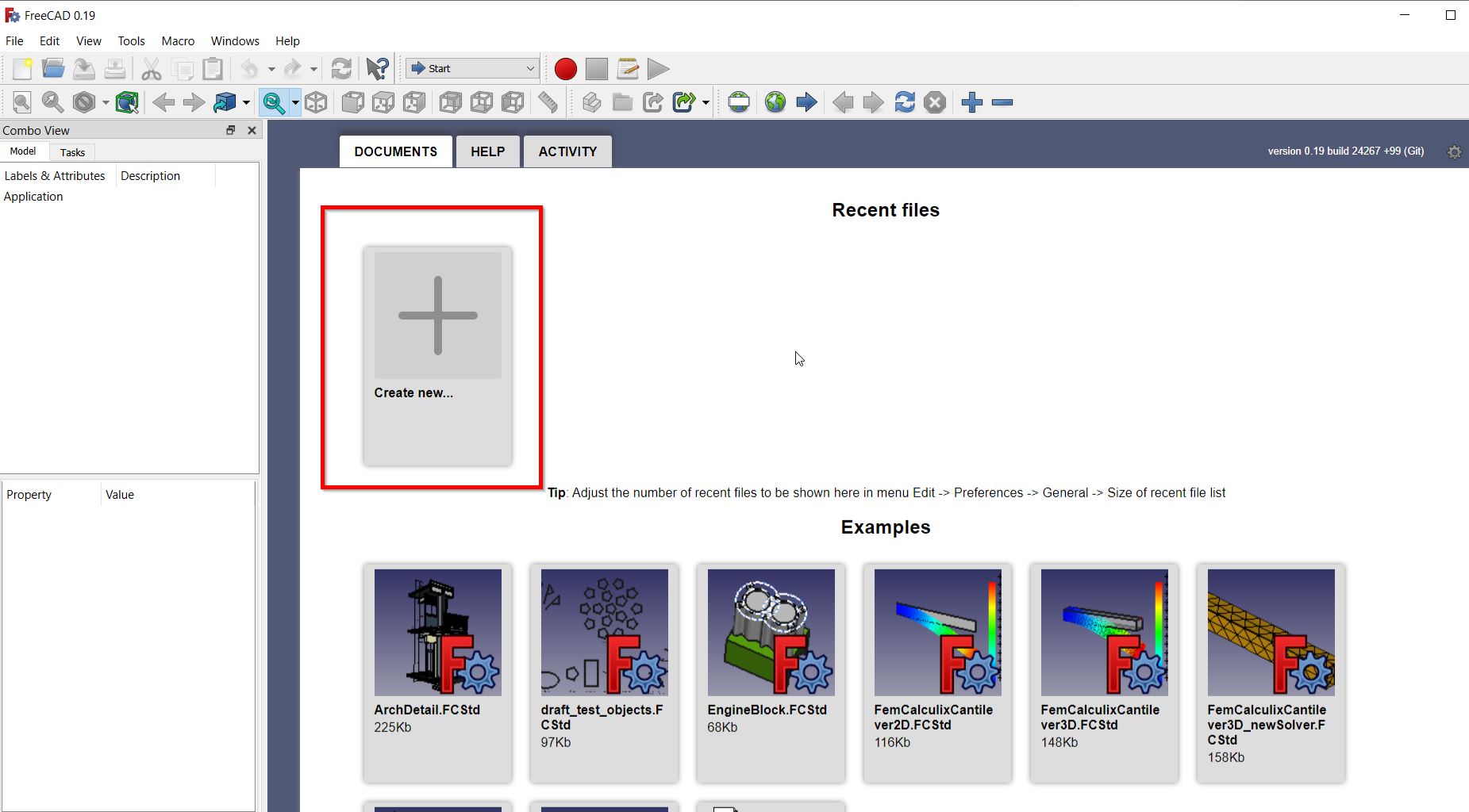
- I have pressed “Create New”, as follows:
- To start with the sketch, I have pressed on “Sketcher” from the main menu:

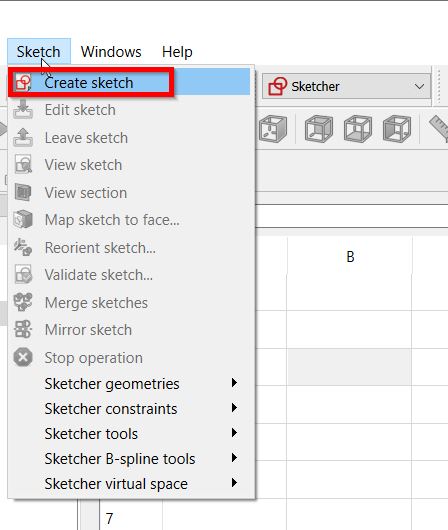
- Clicking then on “Sketch” and “Create Sketch” :

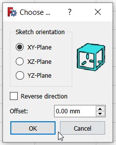
- The plane chosen was {XY-Plane} :
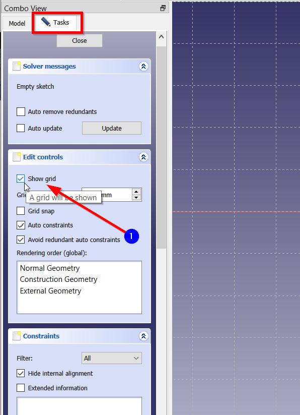
- Display the grid by clicking on “Tasks” > “Show Grid” as follows:
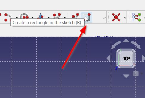
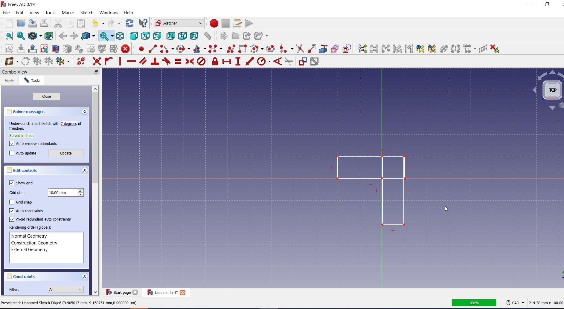
- Then, I created the square using the “Create Rectangle” tool selected from here:
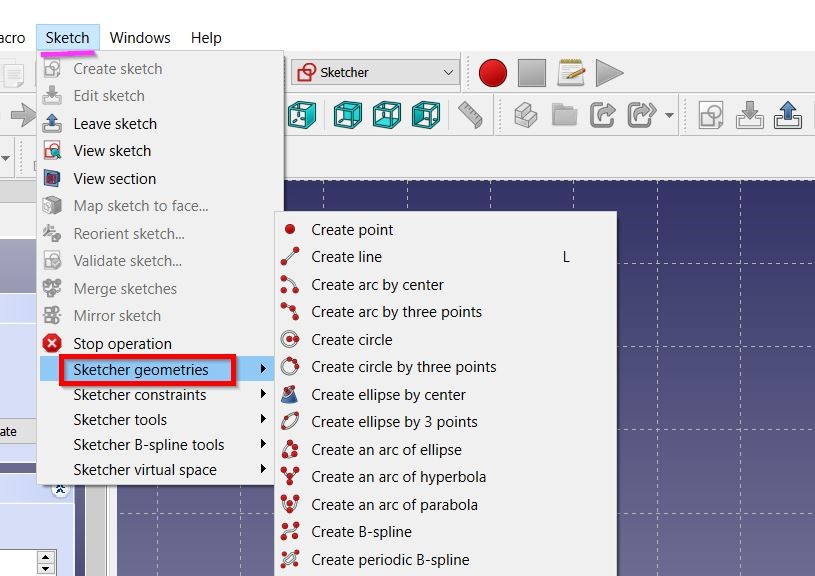
You may also draw the rectangle from the following button:
-
Then, I drew the three rectangles in the center of the rectangle.
-
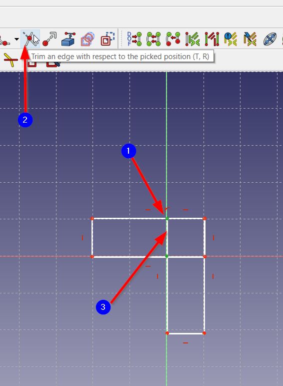
Afterwards, I roughly drew the joints using “Create line” tool on the four sides and used “Trim an edge with respect to the picked position” tool to remove the extra parts. As follows:
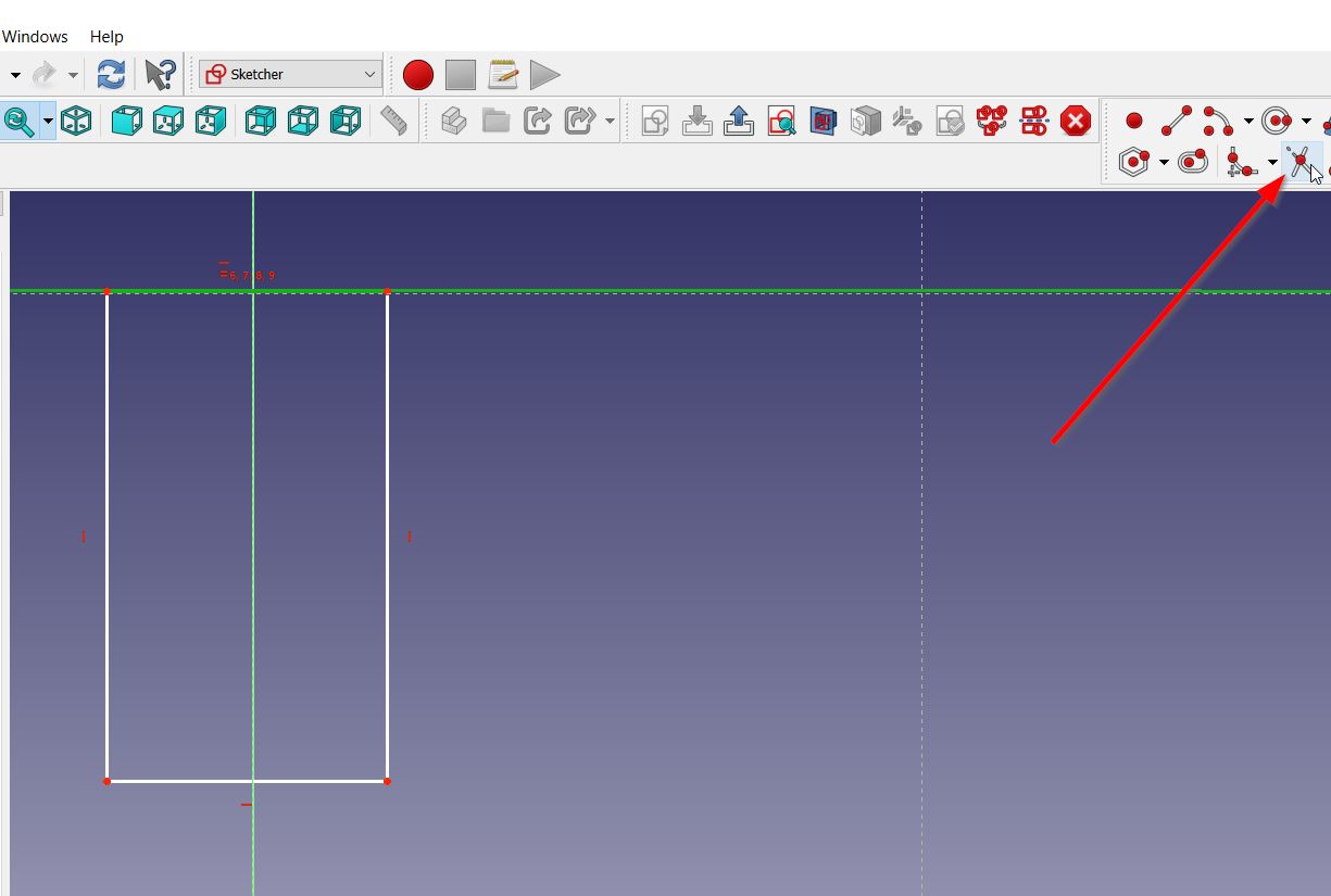
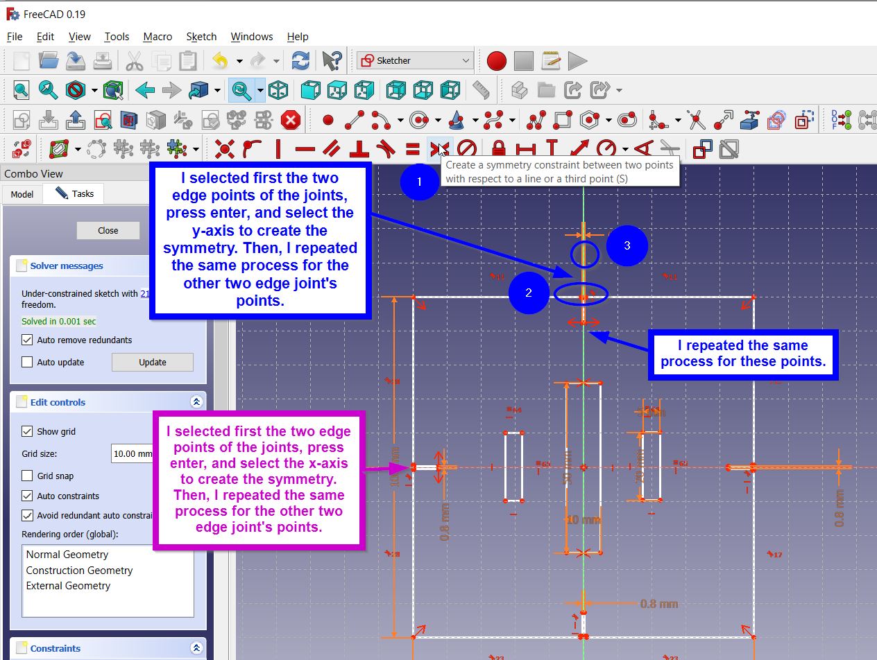
- To ensure that all the joints are in the center I used the “Create Symmetry” tool. As shown here:
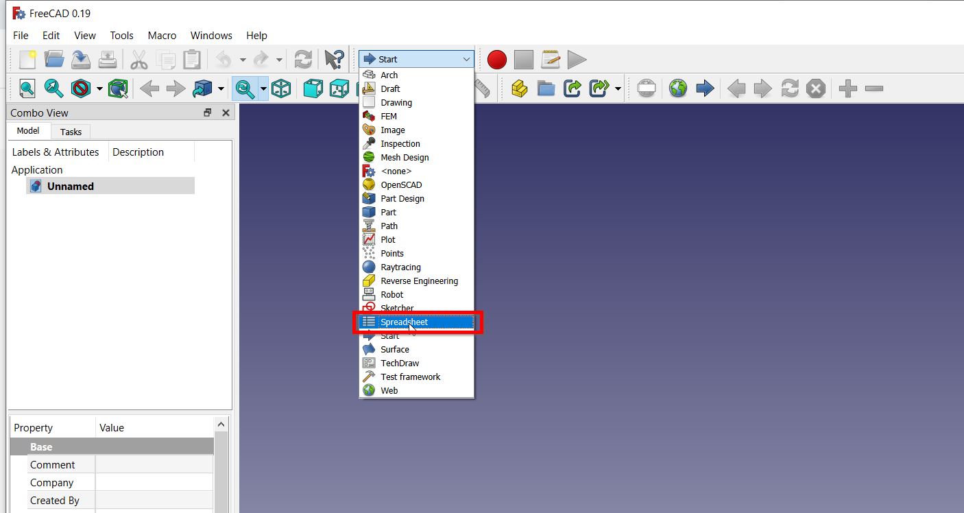
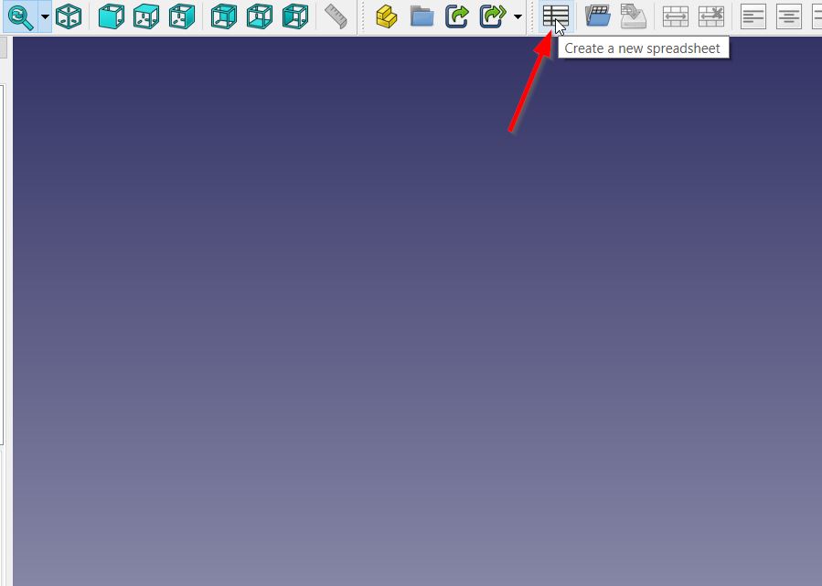
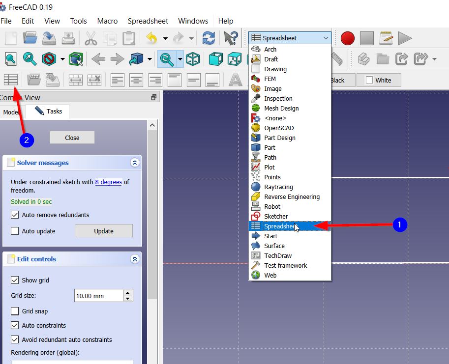
- To create parameters I have then pressed on “Start” > “Spreadsheet” > “Create New Spreadsheet”
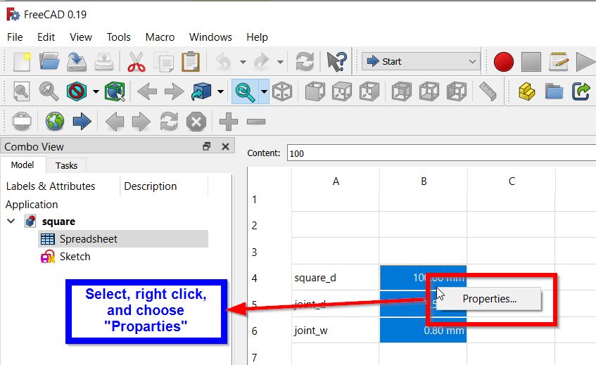
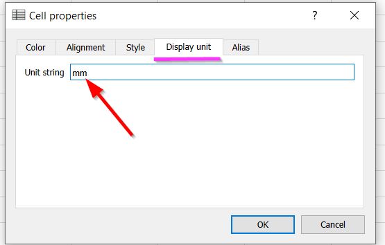
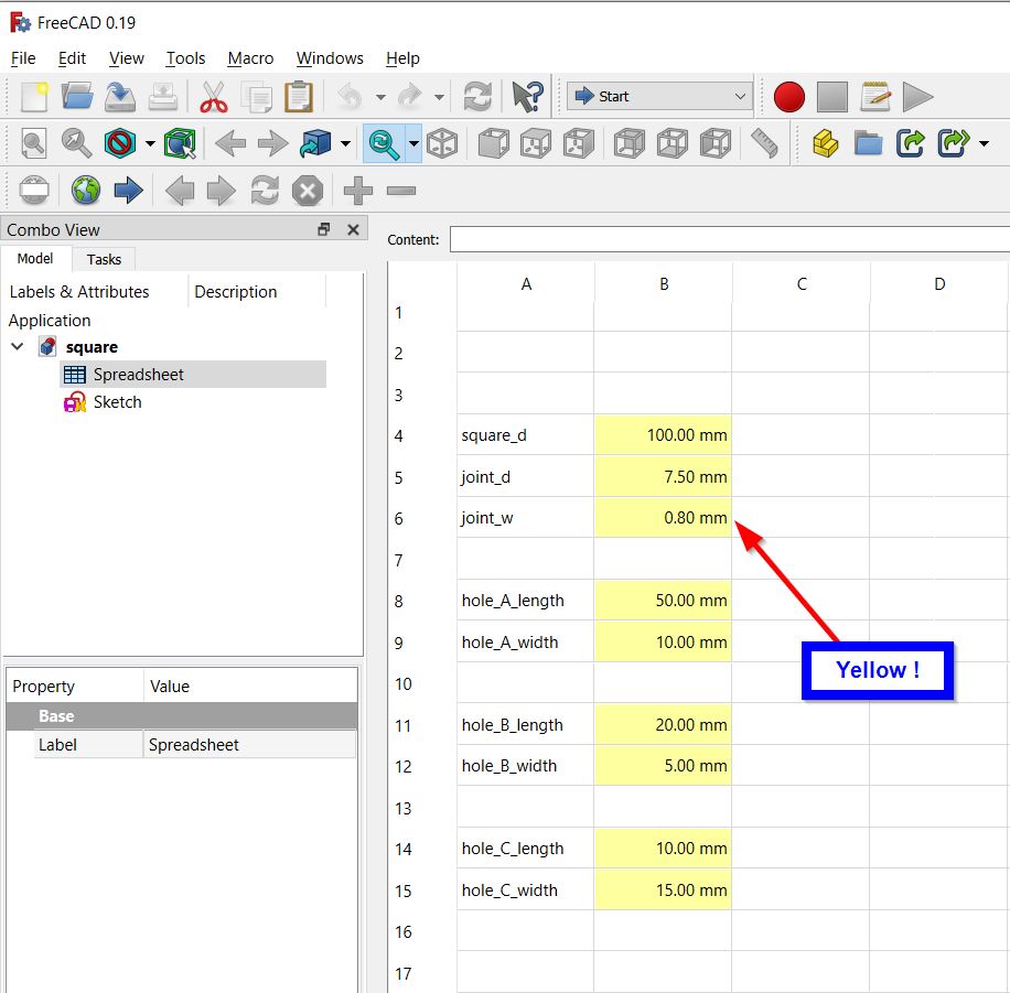
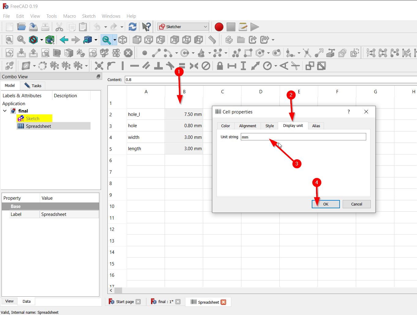
- To set the parameters, I filled in the sheet, selected the column, right clicked and press “Properties” button, and change the unit from “Display Unit” button.
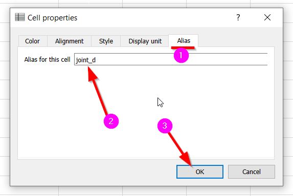
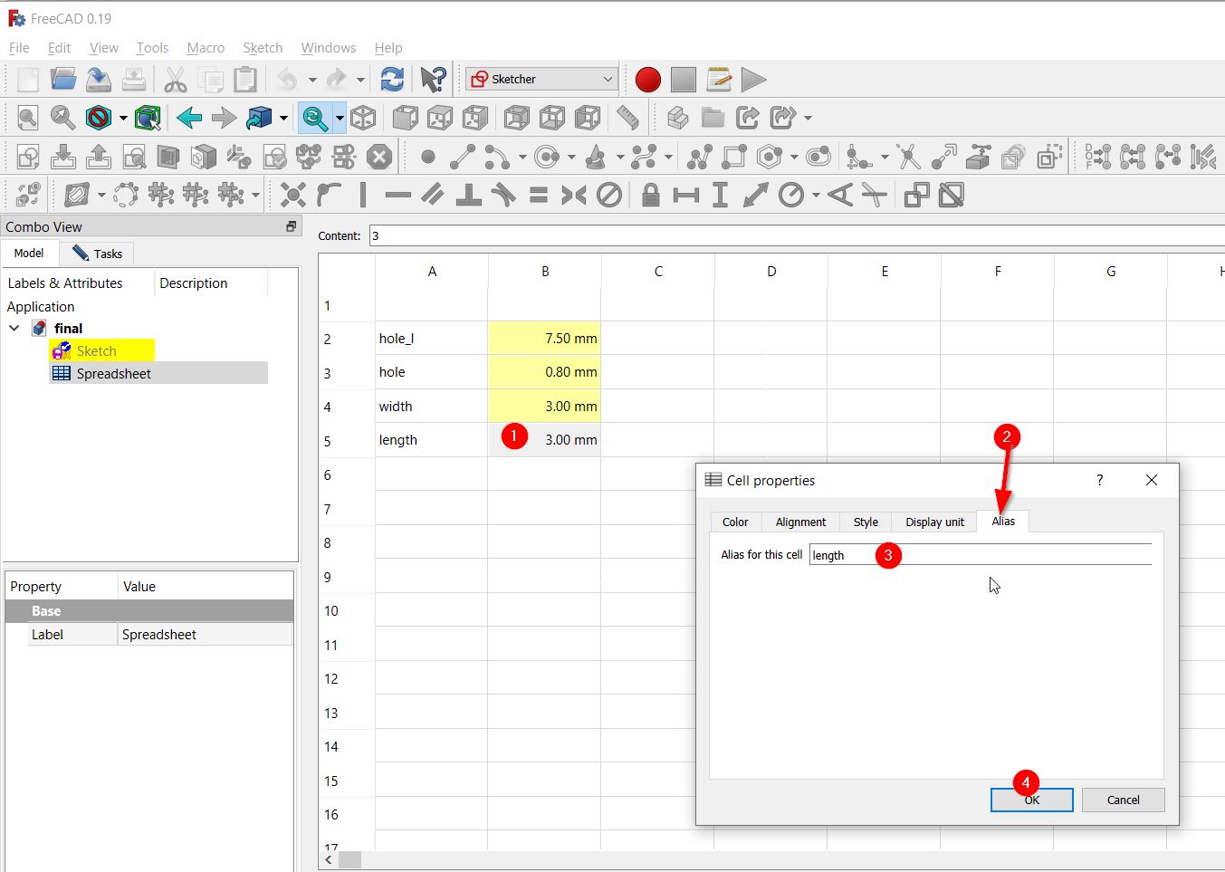
- Then, I selected every cell separately and define it, by right clicking on the cell, press properties, clicked “Alias” button, and type the cell’s declaration name. As shown below:
When all the cells are defined, they have changed to be highlighted will yellow color as follows:
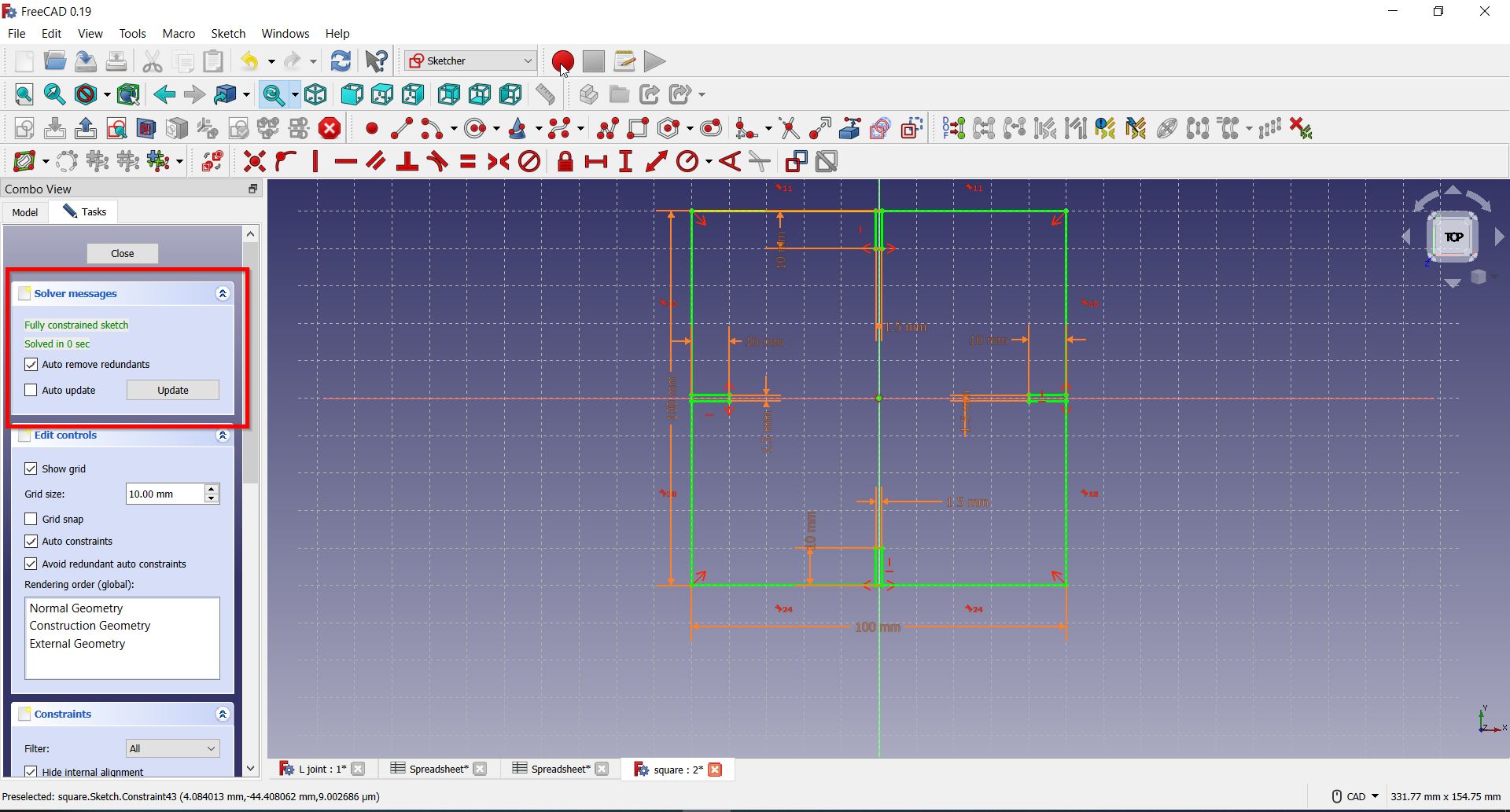
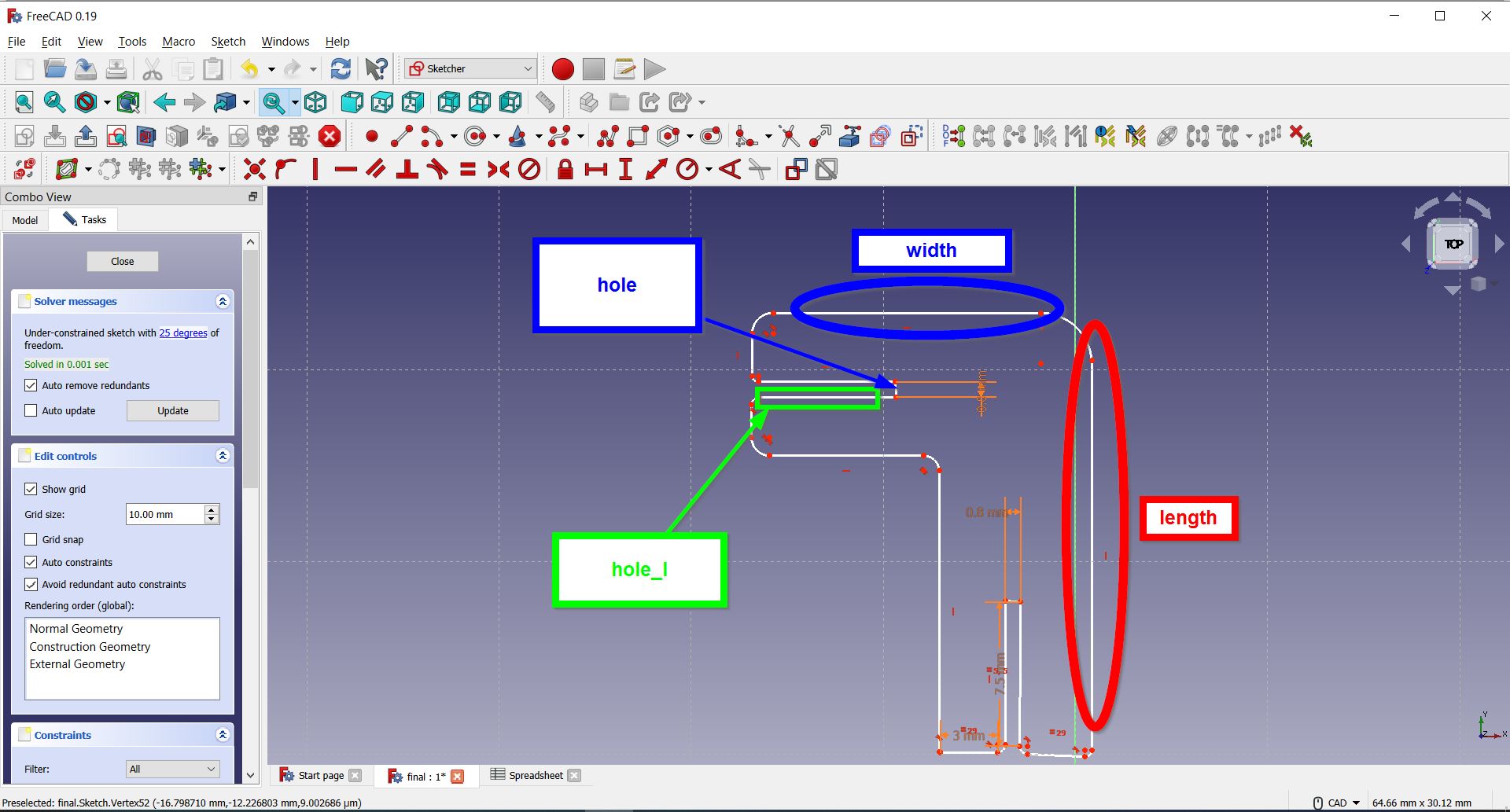
To have further insights, the following image distinguishes the parameters set above:
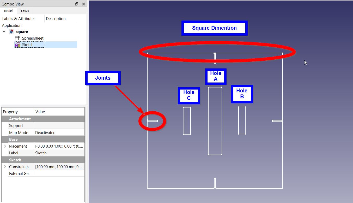
- Finally, I have set the parameters as follows:
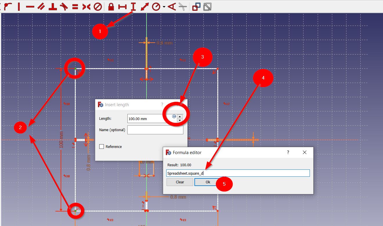
1- Clicking on either the “Horizontal Distance” or “Vertical Distance” tool, then select two points.
2- Then, click on “Formula Editor” button and and insert the following syntax [[Spreadsheet.parameter’s name]]. As follows:
I repeated the same step for all the shape.
Note: Make sure that your design is ” Full Constrains” & “Solved” to be apple to export and cut it.
Joints Design
I fun our 4 trials to get the perfect best-fit. I will present to you here the final sketch design steps. Using FreeCAD Software, I have accomplished the following steps:
- I have pressed “Create New”, as follows:

- To start with the sketch, I have pressed on “Sketcher” from the main menu:
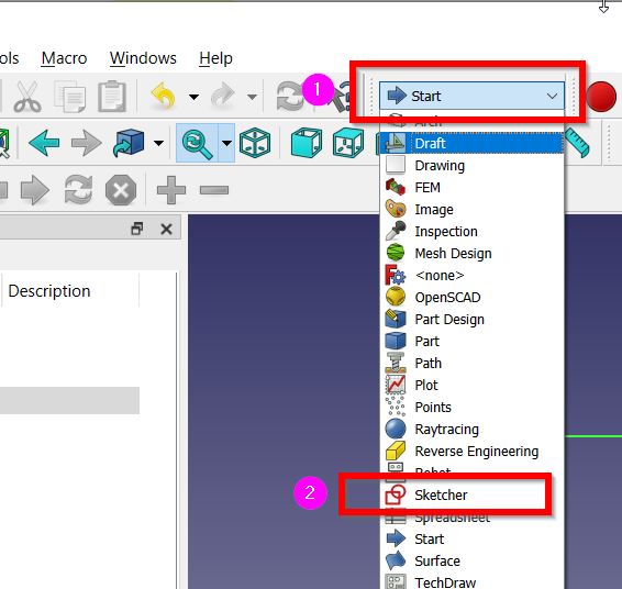
- Clicking then on “Sketch” and “Create Sketch” :
- The plane chosen was {XY-Plane} :

- Display the grid by clicking on “Tasks” > “Show Grid” as follows:

- Then, I created the joint by drawing two squares using the “Create Rectangle” tool selected from here:

- The “Trim an edge with respect to the picked position” tool was then used to remove the extra lines. As follows:
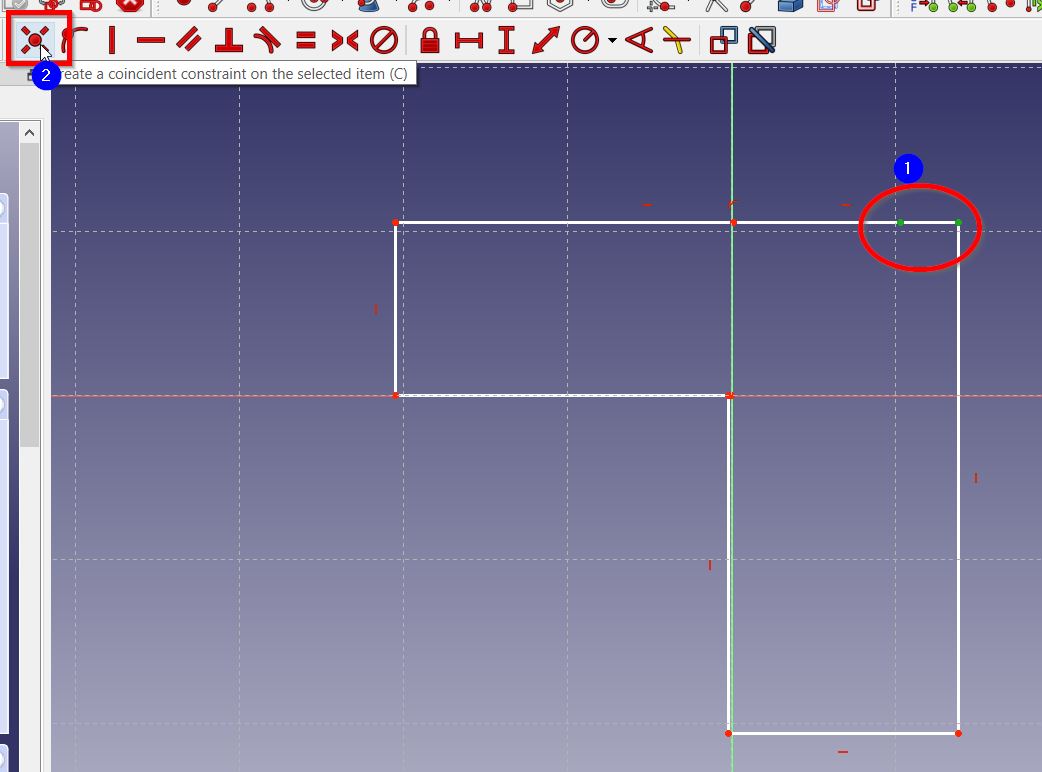
- When there is extra unnecessary edge point, I select two points, and create a coincident constrains between them. As shown below:
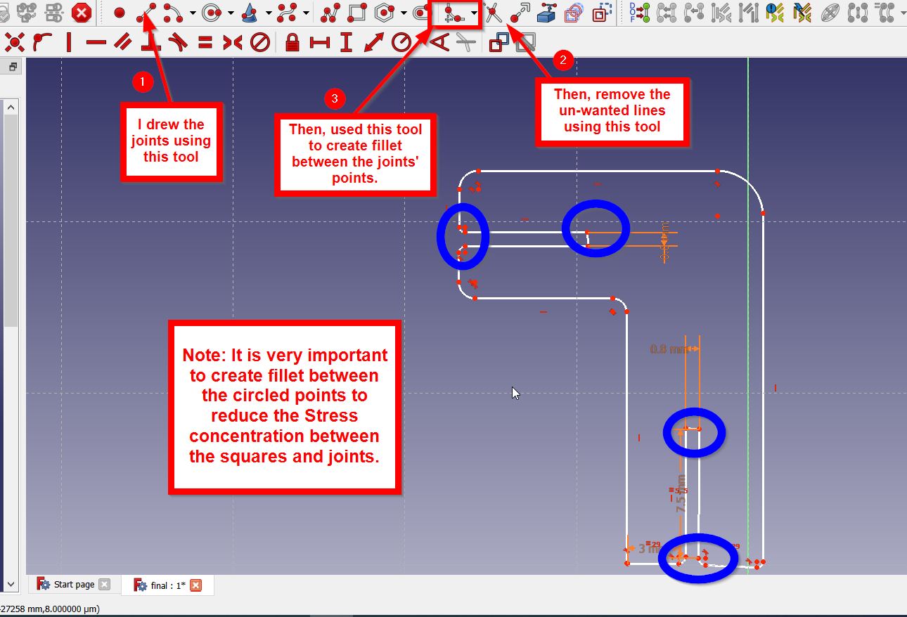
- Afterwards, I drew the joints using “Create line” tool, then trim the extra lines, and finally I used “Create Fillet” tool to be created between two points.
- To create parameters I have then pressed on “Start” > “Spreadsheet” > “Create New Spreadsheet”
- To set the parameters, I filled in the sheet, selected the column, right clicked and press “Properties” button, and change the unit from “Display Unit” button.
- Then, I selected every cell separately and define it, by right clicking on the cell, press properties, clicked “Alias” button, and type the cell’s declaration name. As shown below:
When all the cells are defined, they have changed to be highlighted will yellow color.
To have further vision, the following image distinguishes the parameters set above:
- Finally, I have set the parameters as follows:
1- Clicking on either the “Horizontal Distance” or “Vertical Distance” tool, then select two points.
2- The “Formula Editor” button is clicked and insert the following syntax [[Spreadsheet.parameter’s name]]. As shown here:

I repeated the same steps for all the shape.
Cutting process
To cut my design I did the following steps:
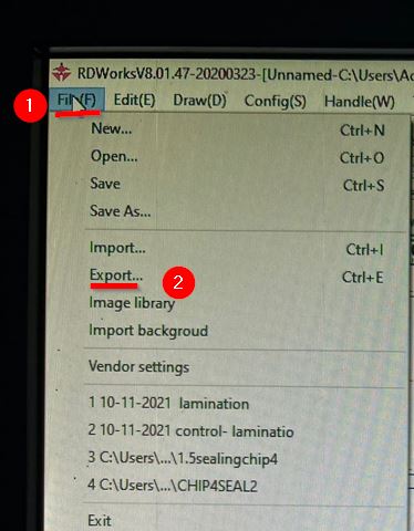
- I have save the design as .dxf format and then import the design in RDWorksV8.01.47 by pressing File > Import as follows:
-
I then set the speed= 35 and power=35. Afterwards I have uploaded the design to the machine.
-
I placed the material in the right place and set the origin point.
-
After that, I selected the file from the machine and clicked “Enter” as follows:
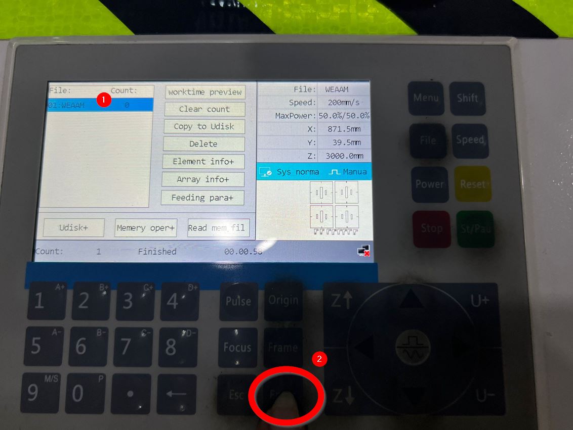
-
I pressed then frame to preview the cutting process before starting.
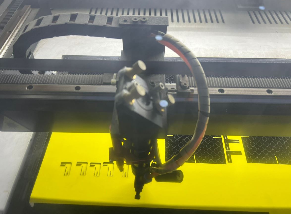
-
Finally, I started the processes by pressing the green “Start” button. Please note that I made sure to close the machine door during the cutting process.
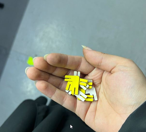
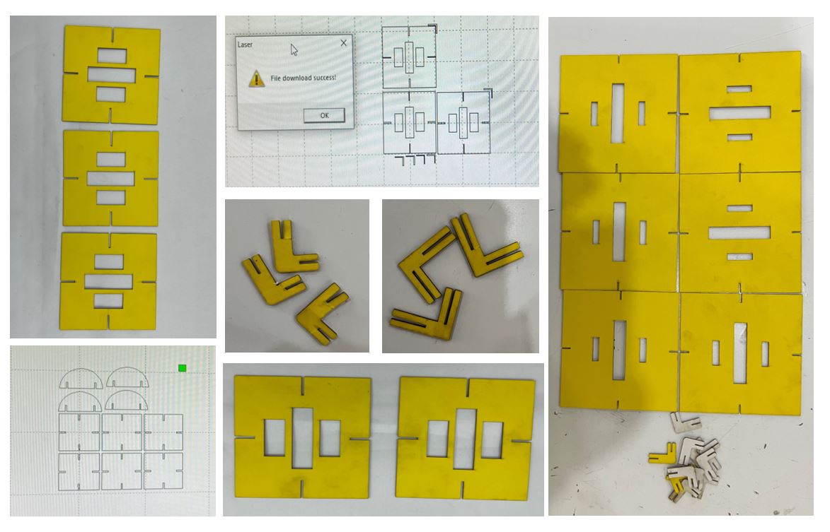
These image present my different trials to test the joints & squares:
Hero shot
Model 1
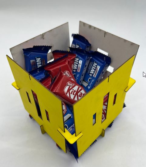
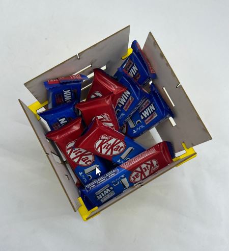
Lets try it out !
Model 2
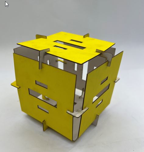
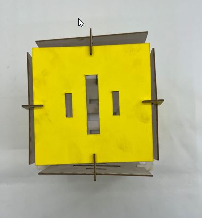
Lets try it out !
Design files
Resources
Thank you for reading !