5. 3D printing and scanning
Week Objectives:
As a Group:
- Test the design rules for your printer(s)
- Document your work and explain what are the limits of your printer(s) (in a group or individually)
As an Individual:
- Design and 3D print an object (small, few cm3, limited by printer time) that could not be easily made subtractive
- 3D scan an object, try to prepare it for printing (and optionally print it)
Introduction
During this week, we have covered both the “3D Scanning” and “3D Printing” concept.
3D Scanning concept
3D scanning is a technology for creating high-precision 3D models of real-world objects. It works like this: a 3D scanner takes multiple snapshots of an object. The shots are then fused into a 3D model, an exact three-dimensional copy of the object, which you can rotate and view from different angles on your computer.
Uses:
1) You rely on having accurate 3D measurements in making important decisions
2) You need to capture vast amount of surface measurements quickly and efficiently
3) Need to reconstruct a physical object in 3D to be visualize digitally on screen
Example: 3D scanners help preserve history by capturing delicate artifacts and fossils into 3D digital form. Non-contact 3D scanners, such as structured-light systems, are especially great for this type of application because they capture the object without causing any disturbance to the original.
3D Printing Concept
3D printing or additive manufacturing is a process of making three dimensional solid objects from a digital file. The creation of a 3D printed object is achieved using additive processes. In an additive process an object– is created by laying down successive layers of material until the object is created. Each of these layers can be seen as a thinly sliced cross-section of the object. 3D printing enables you to produce complex shapes using less material than traditional manufacturing methods.
Advantages of 3D Printing:
-
Affordable: 3D printers are more affordable than ever. For instance, the Creality Ender 3 costs around $300.
-
Rapid Prototyping: You can cheaply and quickly create a new prototype with every design modification, unlike the expensive and lengthy prototype machining process.
-
Infinite Geometry and Shapes: 3D printing can create shapes that are hollow with no openings, have extreme undercuts, all features that are impossible by any other manufacturing method.
-
Reduced Waste: In 3D printing, only the essential material is used to make certain parts as it is an additive manufacturing process. This is different from traditional machining, where huge masses of non-recyclable materials are cut to make 3D parts.
-
Print on Demand: Unlike subtractive manufacturing, 3D printing technology does not take up a lot of space for stock inventory as parts can be printed only when ordered or required.
Limitations of 3D Printing:
-
Restricted Build Size: The chamber size integrated into 3D printers is usually relatively small, thereby restricting the part sizes that you can print.
-
The Textures and Color Printing Limitations: It would be incorrect to say that the multiple colors 3D printing is not possible. It sure is. But, it would requires a lot of time and efforts. In addition, printing with wood and ceramics is again a huge challenge therefore users might be restricted with plastic filament.
-
Limitations in accuracy: The precision of a printed part relies on the kind of machine and/or procedure adopted.
-
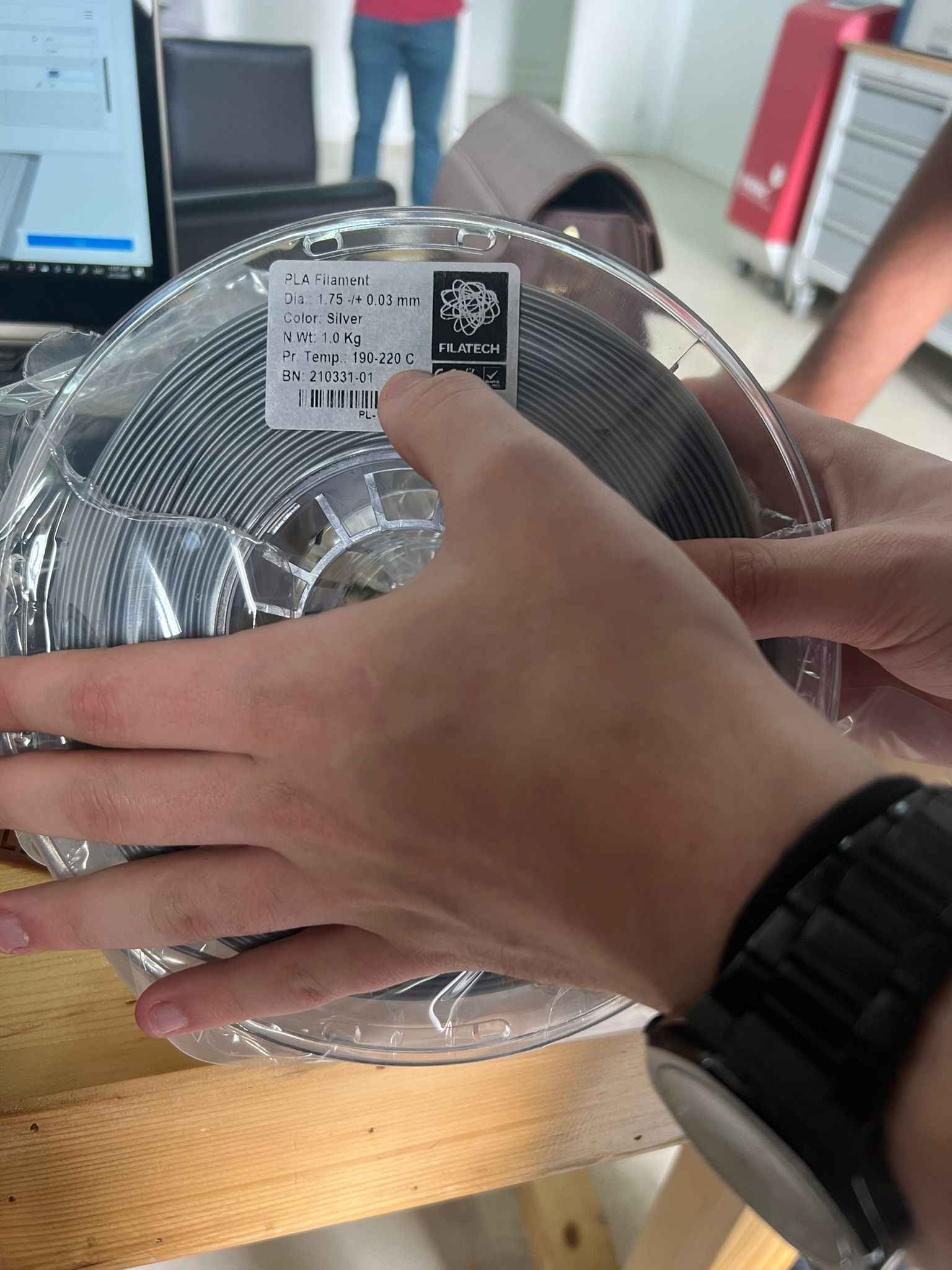
Printing temperature: different temperature should be set for different filament and printer to heat the bed. For instance, PLA filament requires 190-220 C.
-
Nozzle size: The most common standard nozzle sizes are the 0.4mm (or 0.35mm) nozzle used by most current 3D printer. If the nozzle was smaller than about 0.3mm, the resolution; which means how accurately the extruder can feed filament into the hotend might actually start becoming the bottleneck for how well printed part turn out. In addition, when introducing an increasingly smaller constriction to the filament path, the contaminants on the filament blocking up the nozzle is increasing. But, users can create absolutely stunning 3D prints that have completely invisible layer lines and super-fine details as it also allows users to use more layer heights more effectively. On the other hand, a larger nozzle will speed up the design print as not only will it cover a wider track with the same movement, but users will have the option of using taller layers. This may reduce the details printed because the extruded filament might not be heated up enough before it leaves the hotend as it been send through the volcano heater block very quickly.
Group Assignment
For this week I was responsible for documenting the group assignment. Therefore, below you will find an overlook on what we did in the fab lab.
3D Printer
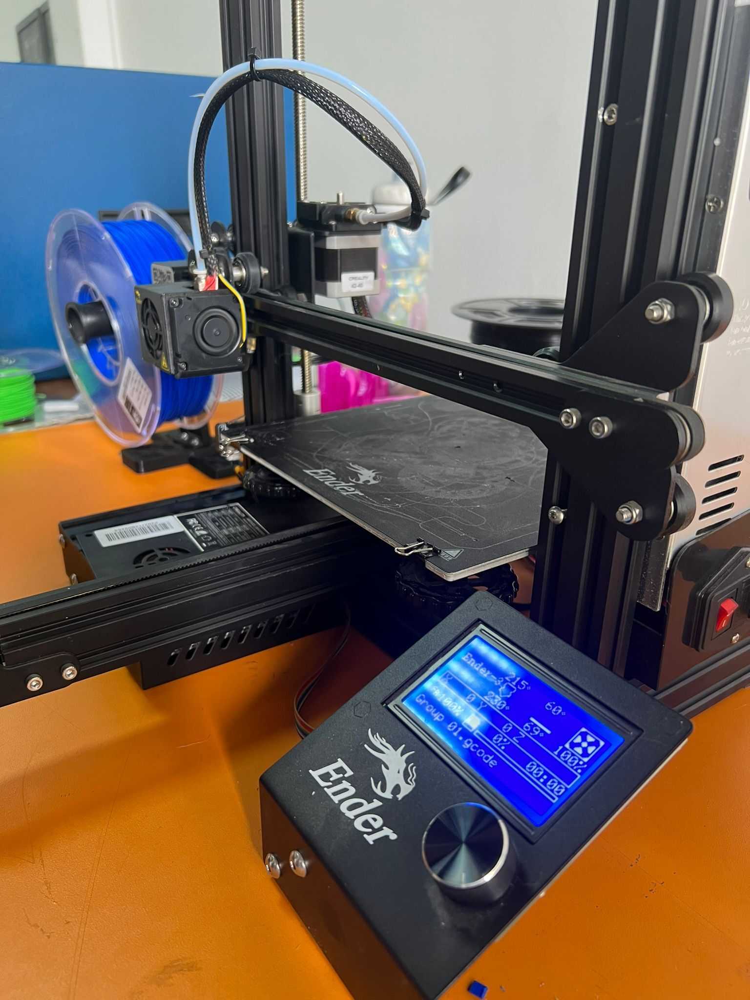
We used Creality Ender-3 3D Printer (with Fused Depositing Modelling technology), that works using a plastic filament (as PLA) spool which is insert into the nozzle extruder. The nozzle is a mechanical part of the 3D printer that extrudes the filament. It can move across both at horizontally and vertically. It melts the filament by conducting thermal energy provided by the heating cartridge and heating block. The design uploaded to the printer can then be produced easily by layering the melted filament on top of each other and the object hardens immediately after it releases from the nozzle.
Plastic Filament Used
PLA filament was available with multiple colors in our fab lab. We used it among others because it is easier to be used and faster to dry.
3D Printer Parameters
The instructor started our session by introduce us to the main 3D printer setting parameters. As follows:
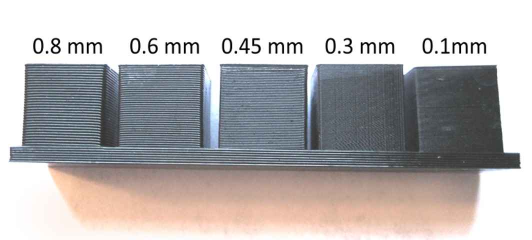
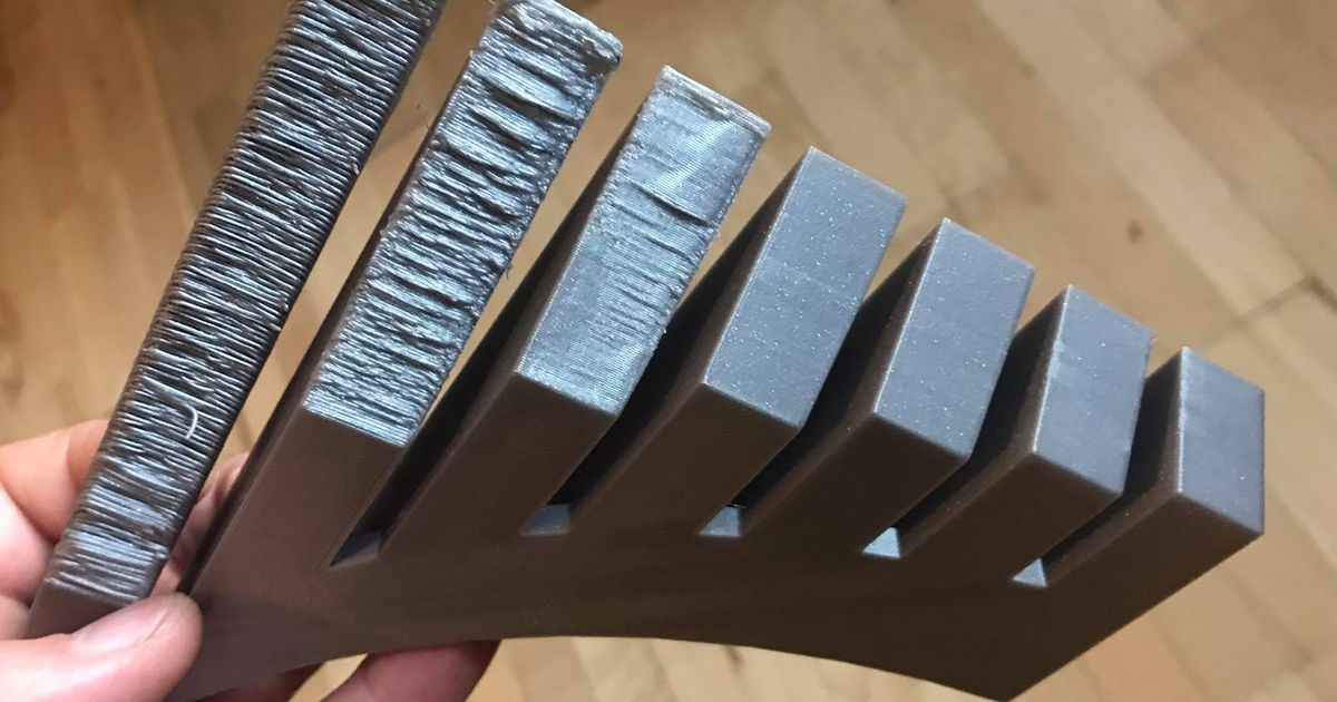
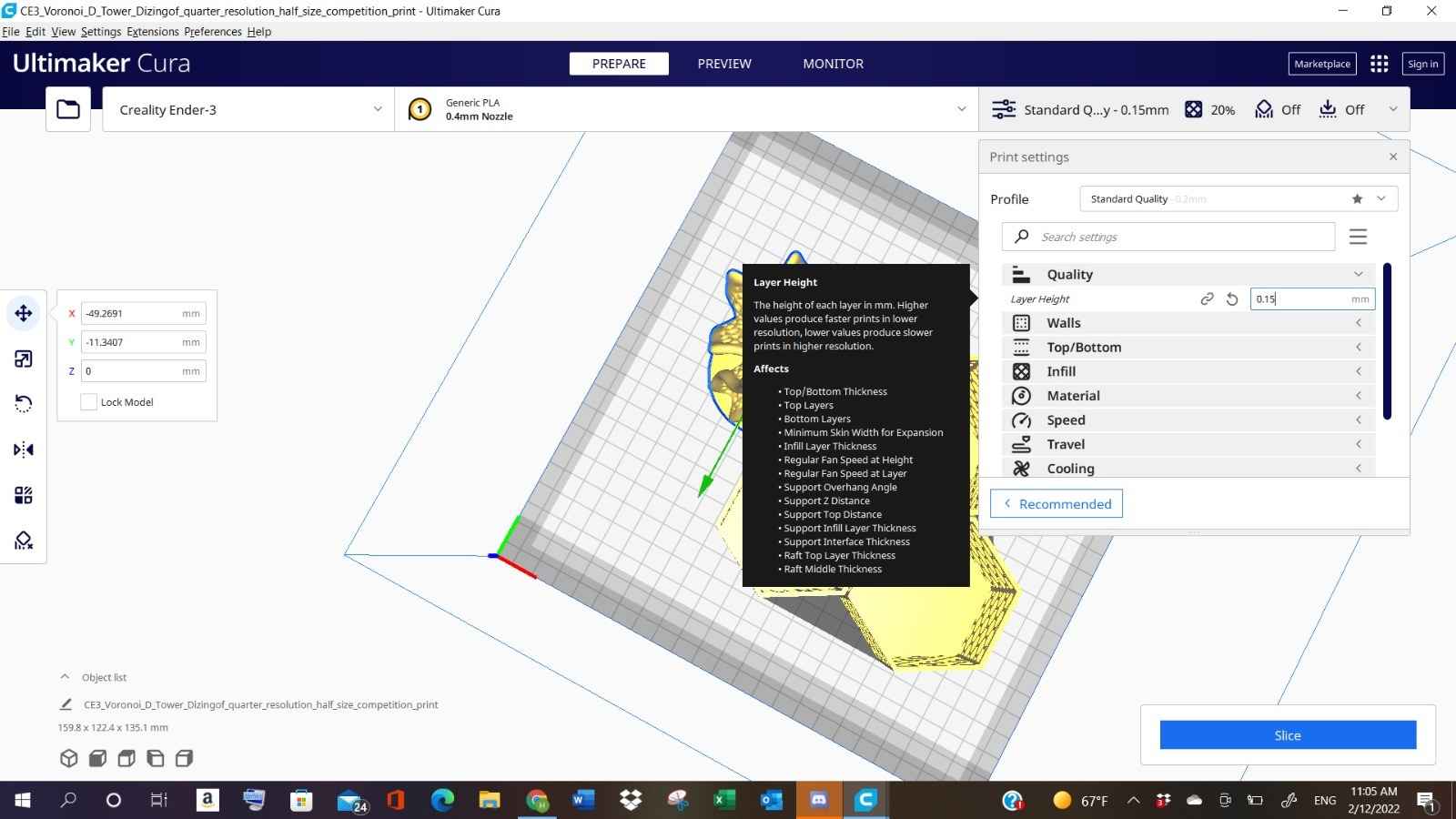
1- The Layer of Height
The layer height refers to each step the 3d printer move up in z direction as it draws each layer of the 3D Print. Essentially what happens is that it will draw a line by line each layer and it’ll move up be a certain amount (layer height). So, the distance between the layers is referred to as layer height. Using a slicer program we can adjusted it and it will have many effects on the final print. If the layer height have been decrease it will increase the objects’ resolution, quality, and smoothness. In addition, the layer height parameter plays role in the object printing speed. Because, usually the printing speed increases by lowering layer thickness. On the other hand, setting the layer thickness too high, will increase the amount of material used and the time spent printing the object.

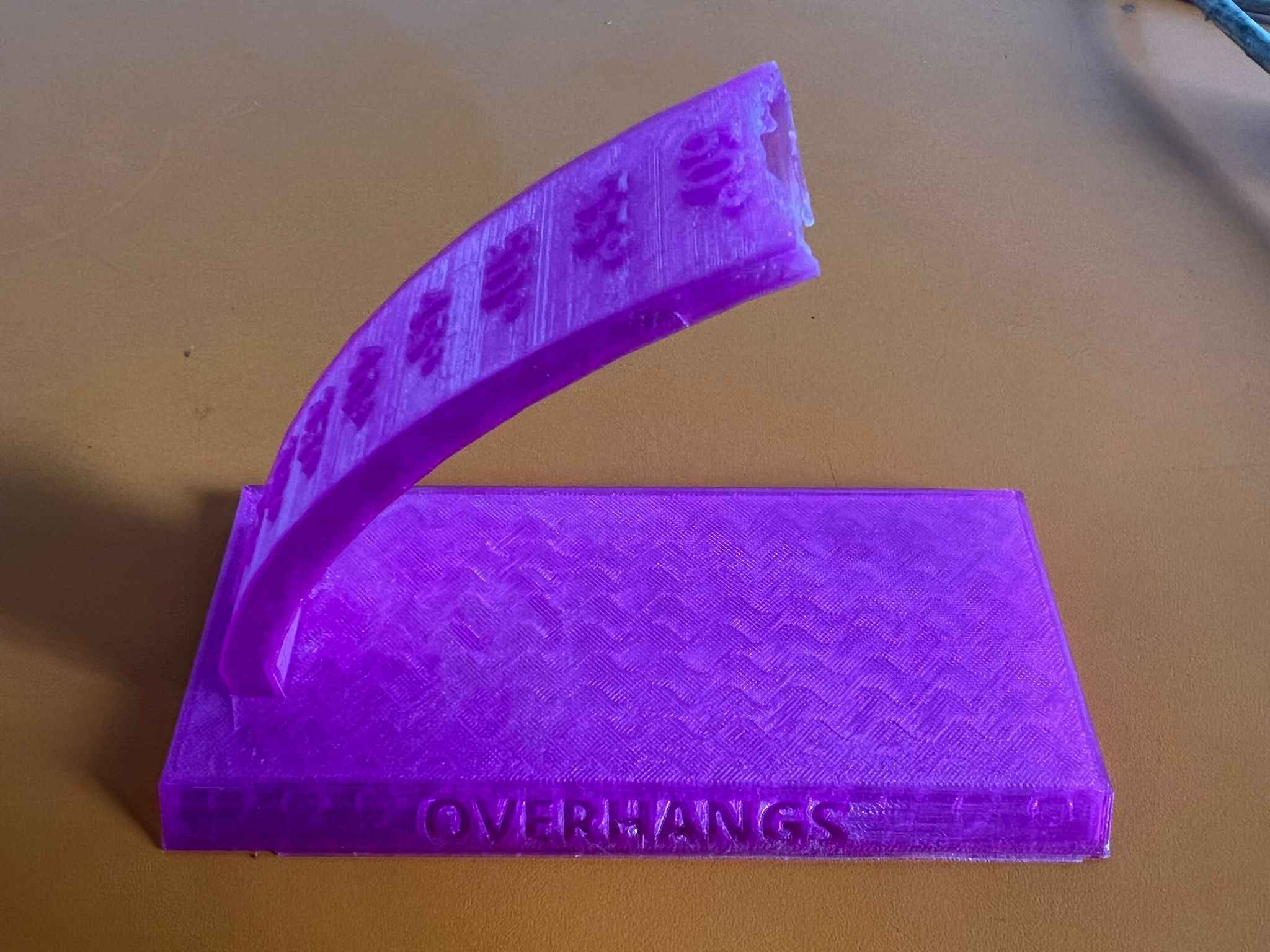
2- Overhangs
Overhangs in 3D printing are the most concern while dealing with arc and curves paths specially when the support is not available below them. This parameter refers to the angle reached compared to the bottom surface. Usually, the higher the angle go the lower the print’s quality would be. Because, the gravity increases upon the filament. But, sometime we can go up with the Overhang to 60% without using support, as shown below in the picture:
3- Support:
Support refers to the layer of filament added underneath the print and can be removed when the printing process is done. It is used mostly to prevent the object from sagging when overhang is increased.

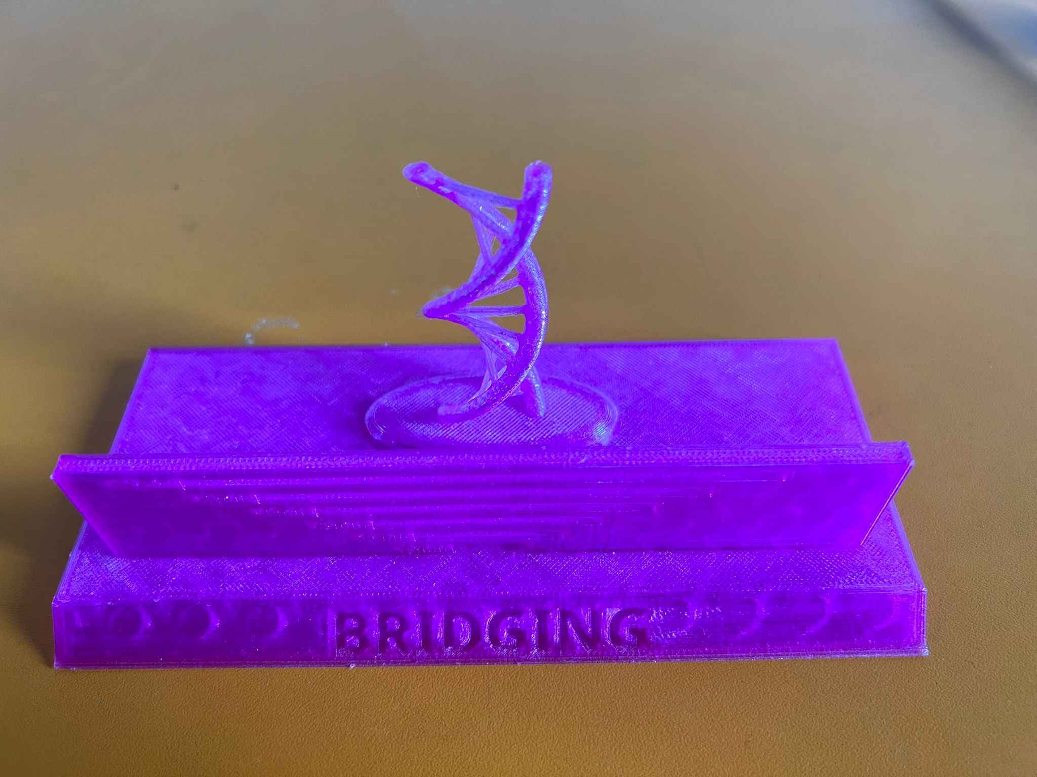
4- Bridging
Bridging refers to the extrusion of filament horizontally to link raised points together. The filament bridge most of the time to sag due to gravity. In addition, there are also multiple factors that may contribute to the bridging failure in 3D printing. For instance, high level of printing temperatures, filament flow rates, and printing speeds.
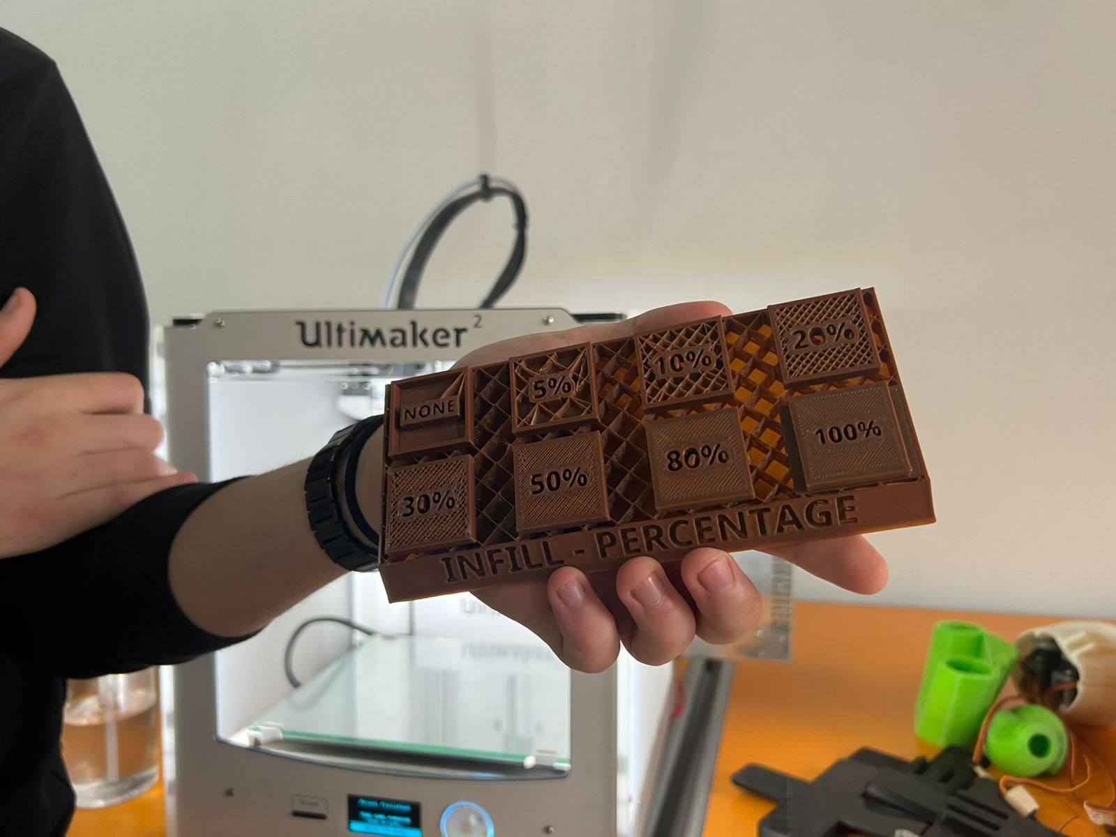
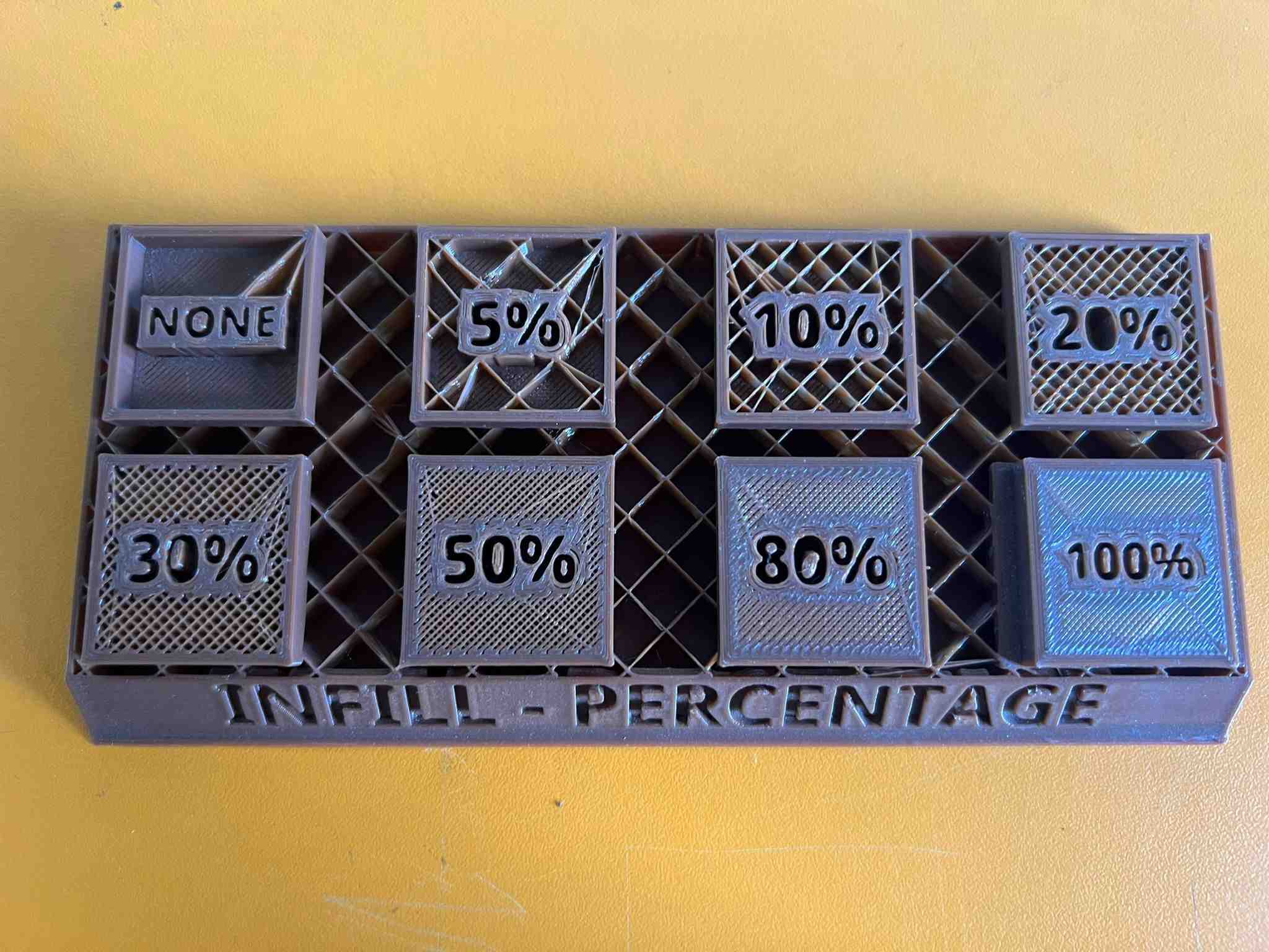
5- Infill
This parameter determines the level of material used to fill the inner part of the print. It have a huge effect on the print’s strength, weight, structure, buoyancy, and more. Increasing the percentage of infill density, will increase the time it takes to manufacturing the object.
6- Shell Thickness
Shell Thickness refers to the outer perimeters of the object. It is also be settled in the slicer program. The higher the Shell Thickness, the strengthen the print would be.

Slicing Group’s Designs
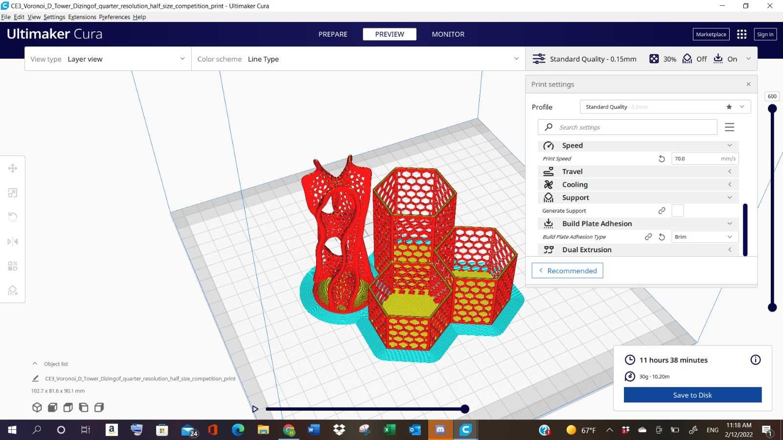
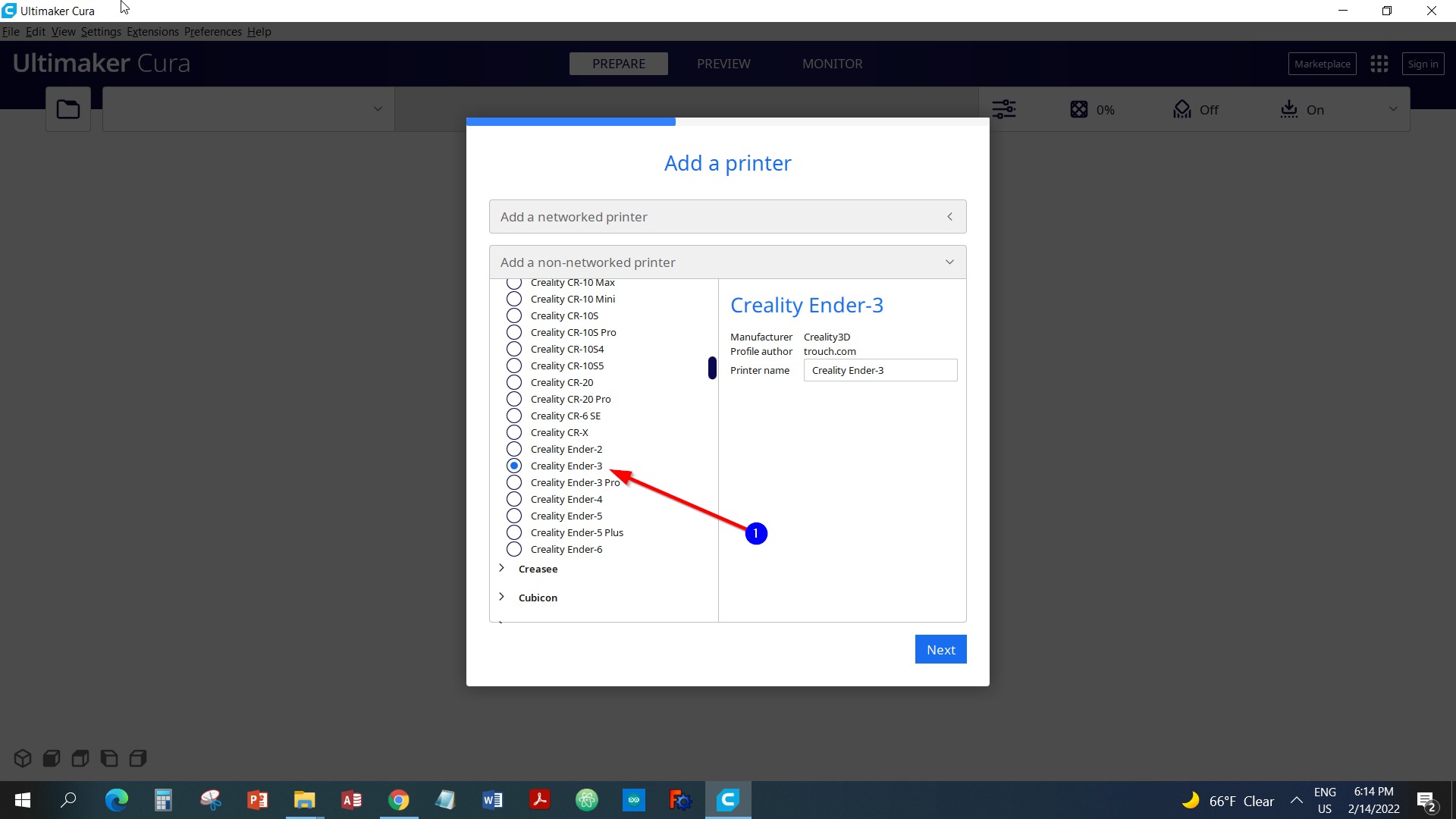
To further develop our knowledge about the 3d printing process. Our instructor provided us with a file that contains a couple design to choose from. After selecting the designs, we uploaded them to the slicing program called Cura. Then, we have starting changing the parameters as follows:
- The printer type is selected:
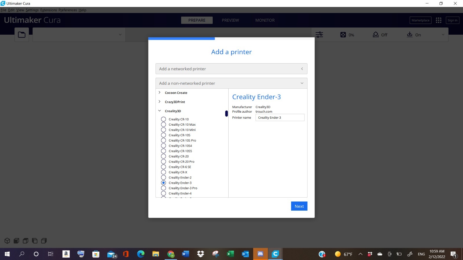
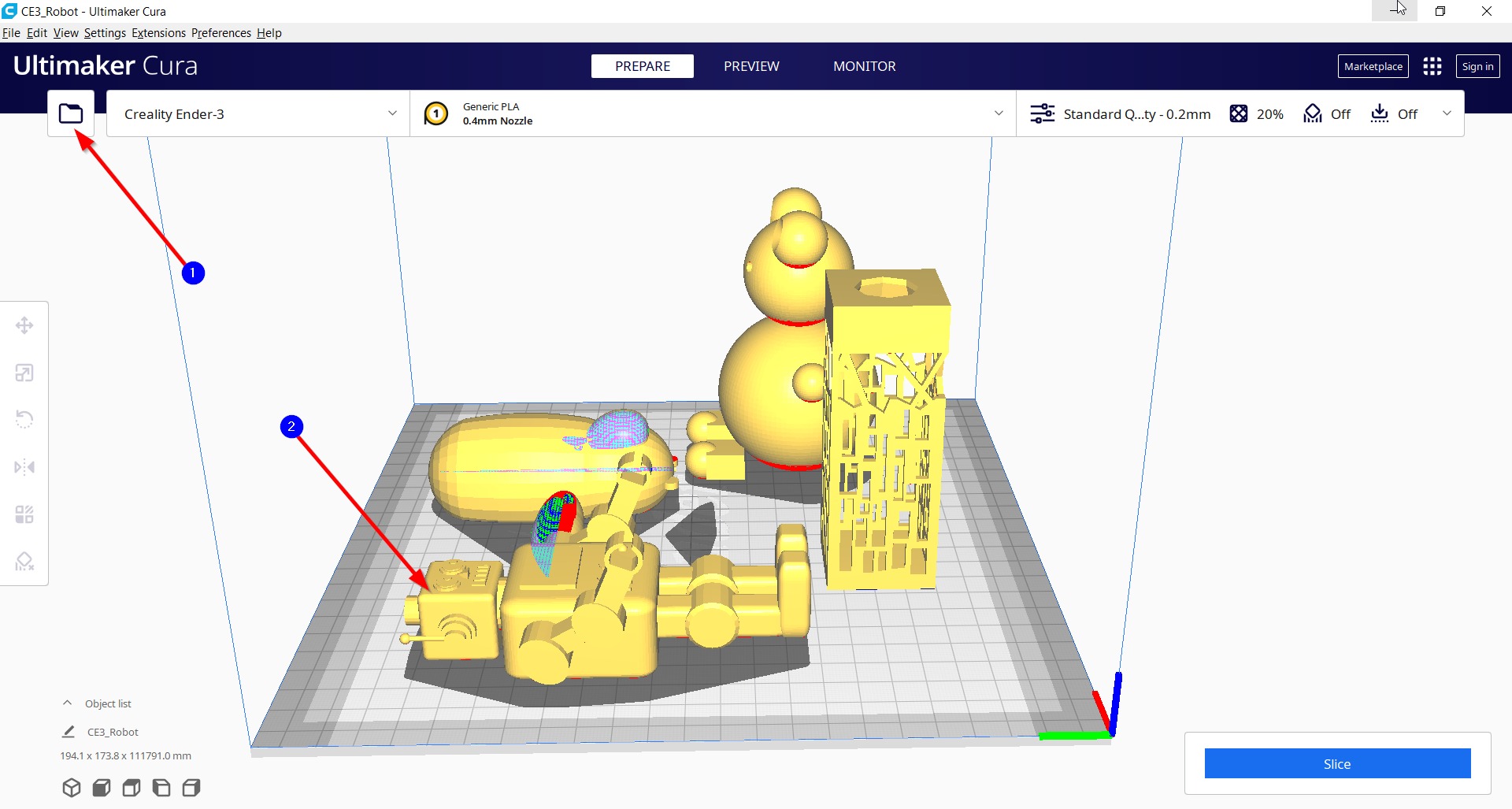
- The design chosen have been uploaded:
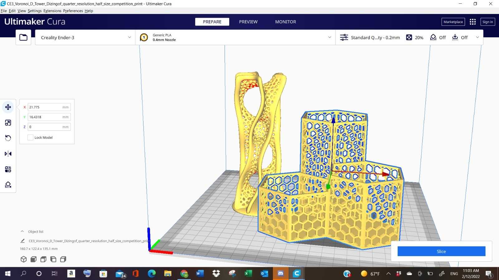
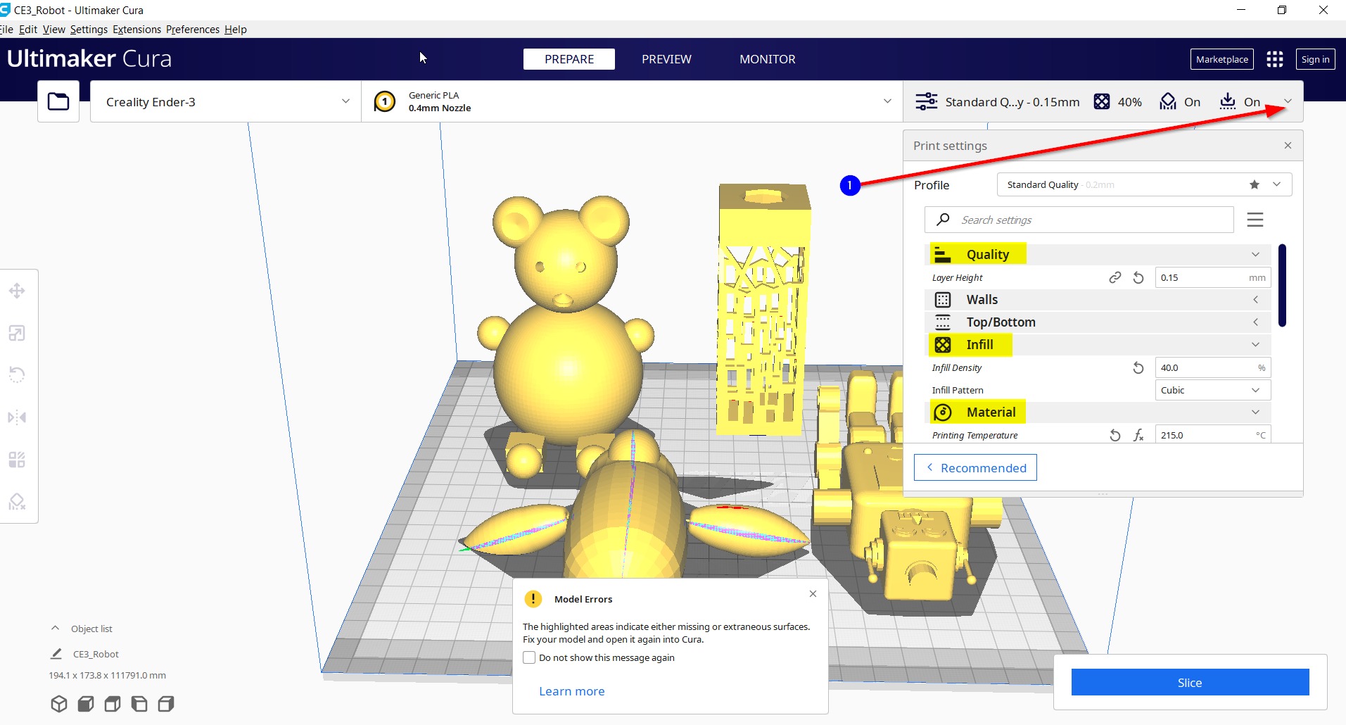
- Select “Customize” from the “Standard Quality” button:
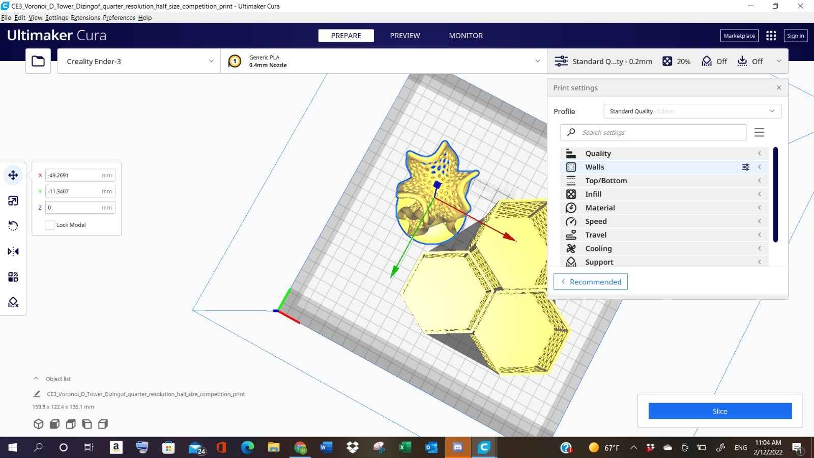
- Editing the Quality level:
- Editing the Infill Parameter:
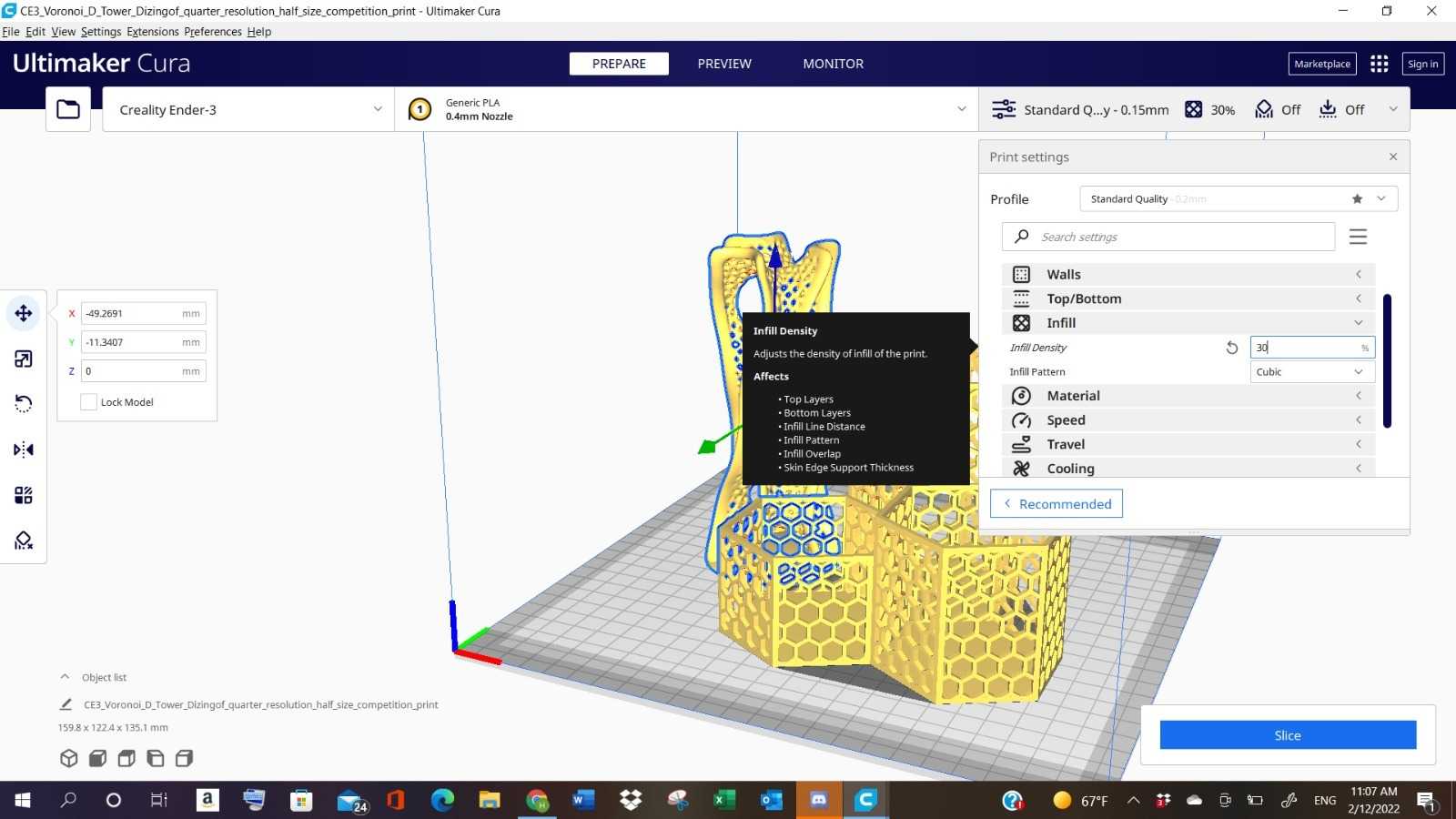
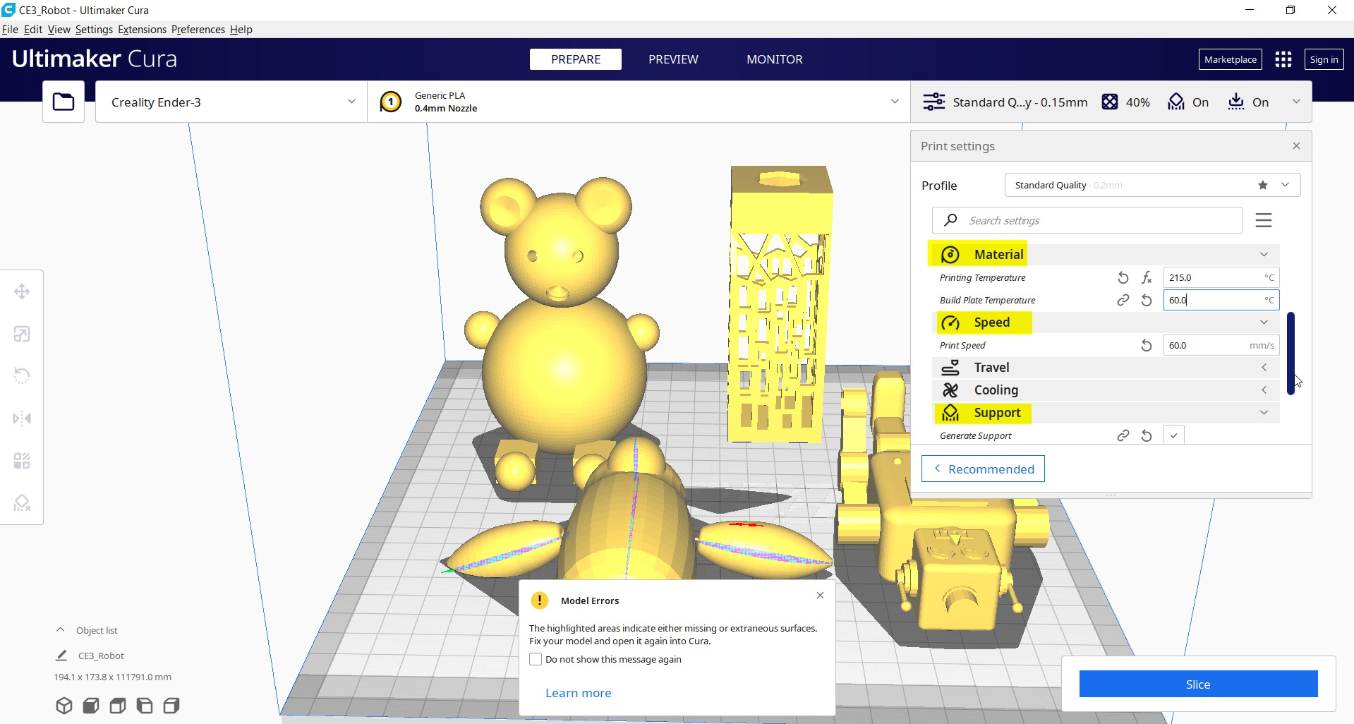
- Editing the Material:
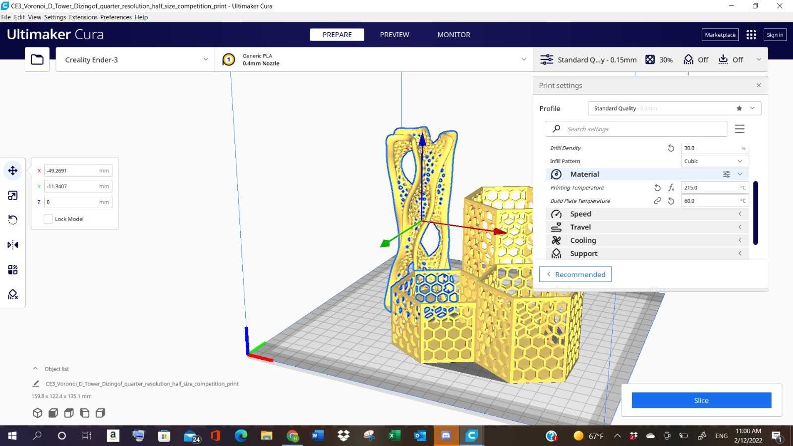
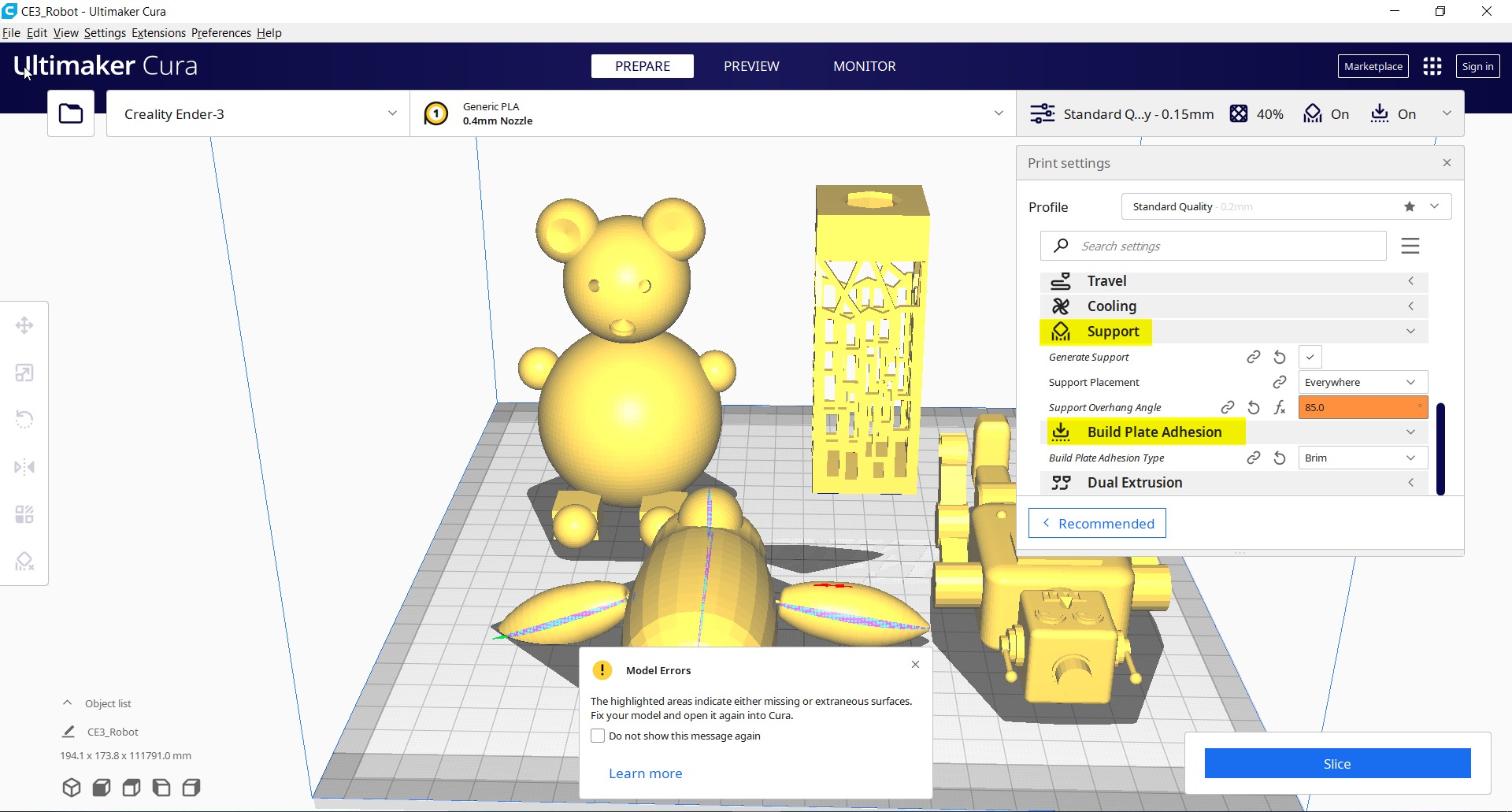
- Editing the Speed and Build Plate Adhesion:
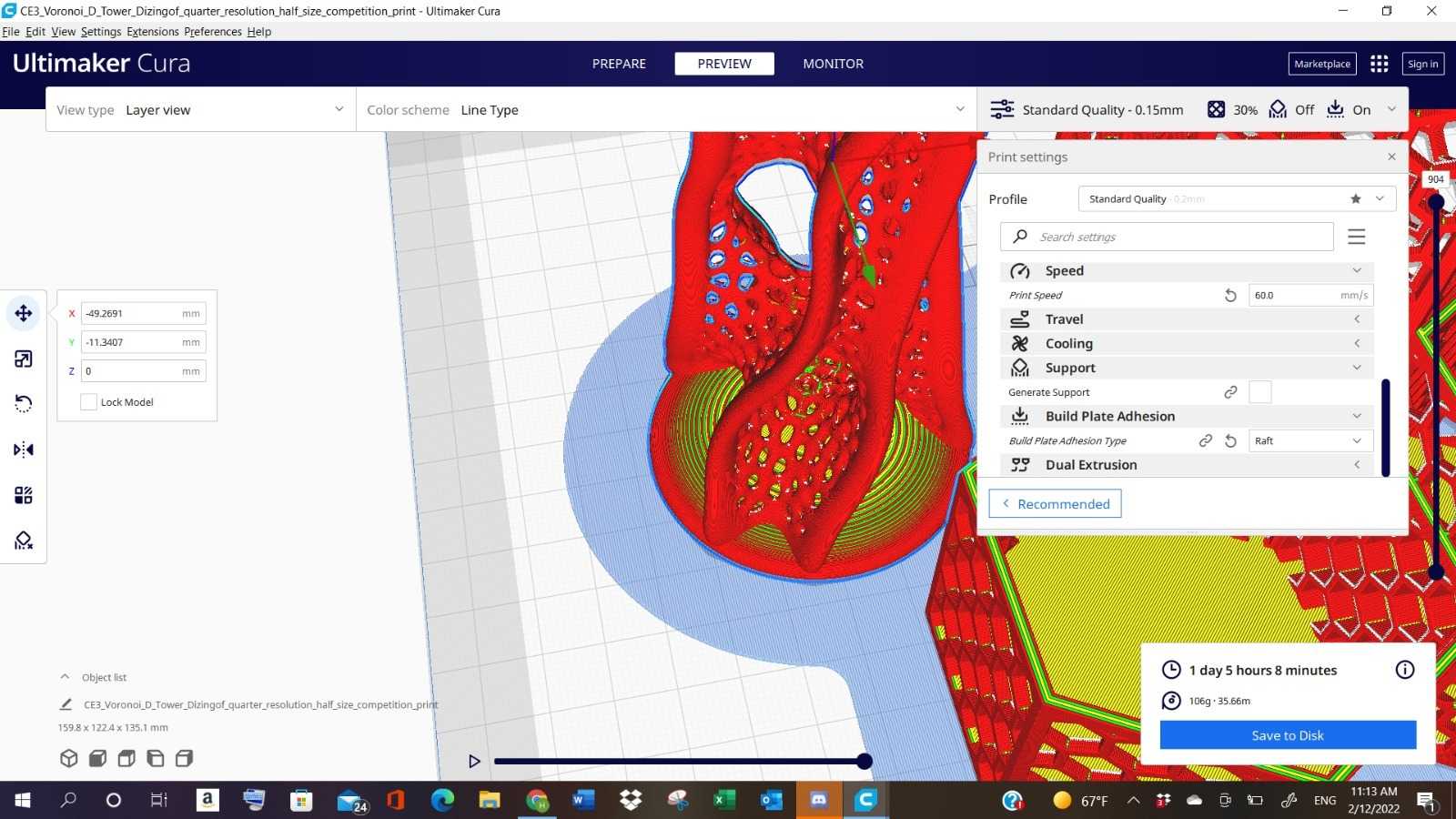
Note: Ruff choice is selected to create a single flat layer “below the object”, to improve both priming extrusion and adhesion to the build plate.
- The “Slice” Button was clicked to calculate the time needed to print the designs:
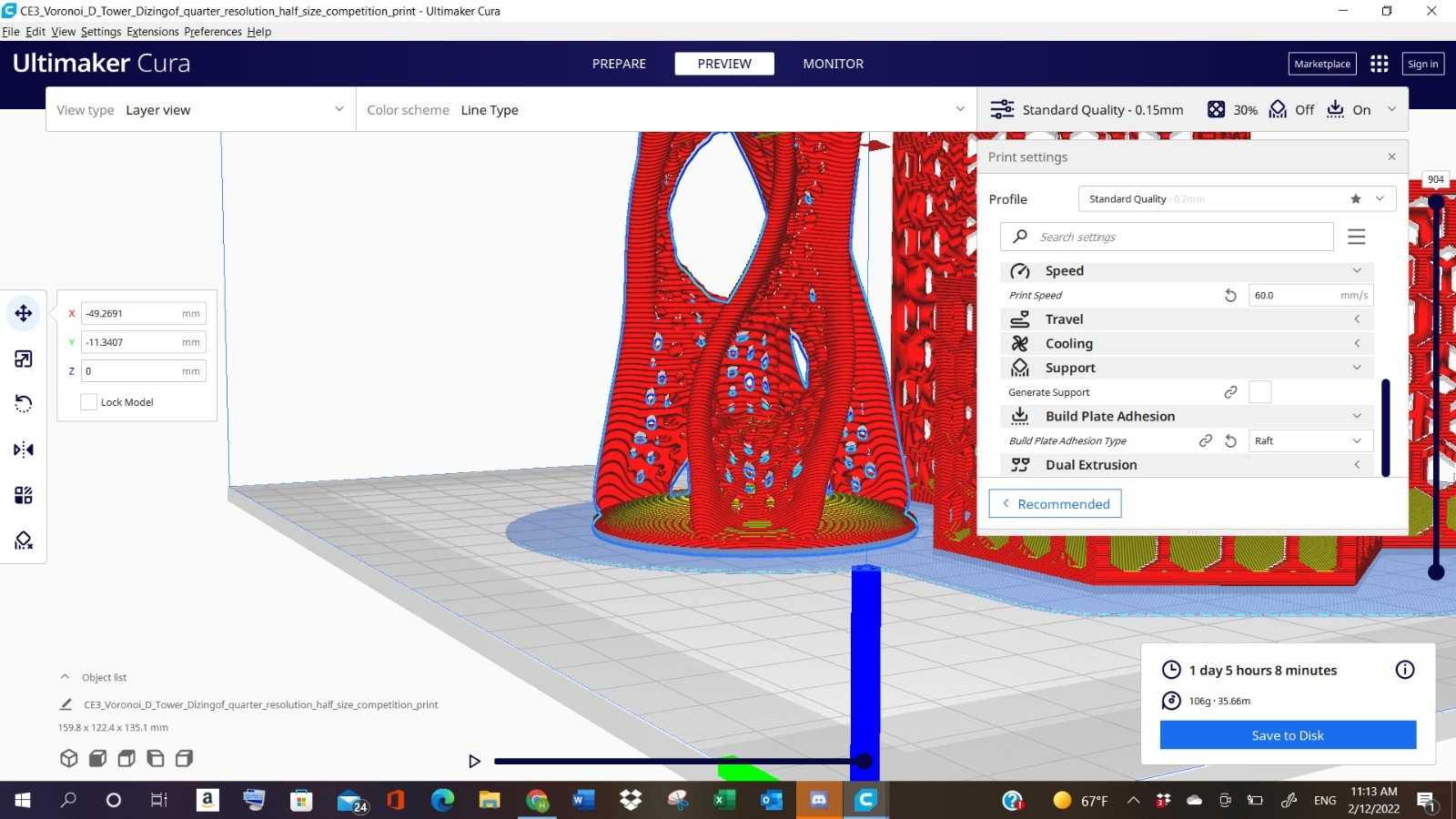
- Then, to reduce the time consumed to print the designs, we have changed the Speed to “70” and Build Plate Adhesion to “Brim”:
Note: Brim choice is selected to create a single flat layer “around the edges for the object’s height”, to improve both priming extrusion and adhesion to the build plate.
Finally, the file is saved as g-code file and saved to the Memory card.
Printing Group’s Designs
The following steps are accomplish with the instructor to Print the designs sliced previously:
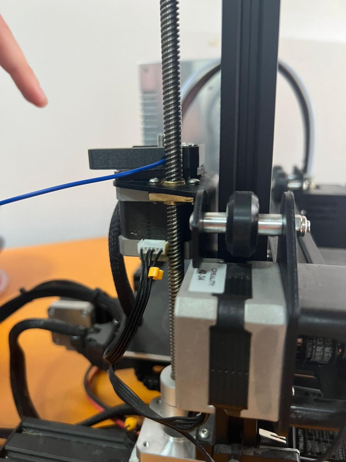
1- The filament was inserted:
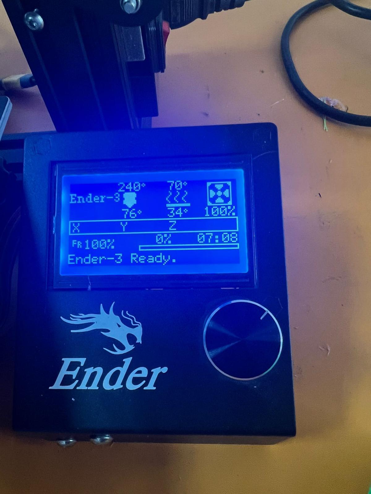
2- The Nozzle and bed temperature was set:
Note: you need to heat the bed to make sure that all your object will not collapse.
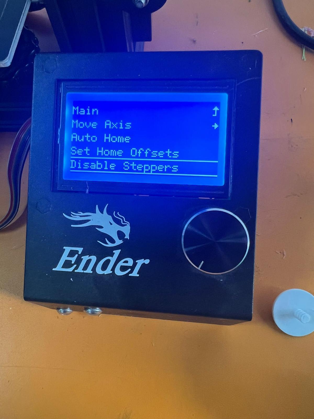
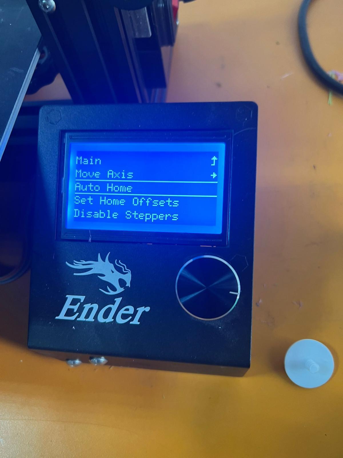
2- The “Disable Steppers” was selected to unblock the nozzle:
3- Collaboration:
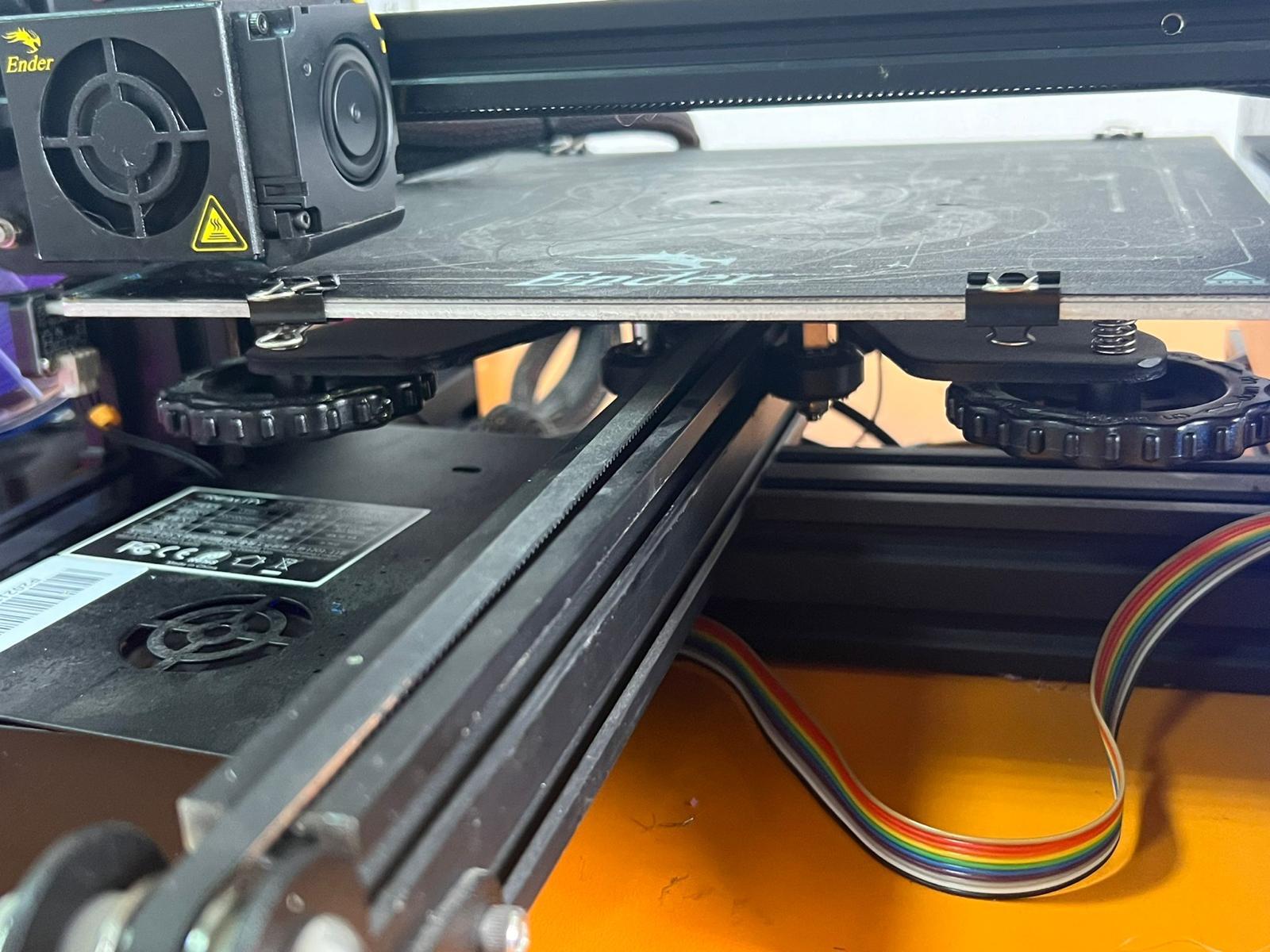
Refer to the process of making sure that the bed is in the right height for the printing.
Note: It needs to be in 0.04mm height (A4 paper).
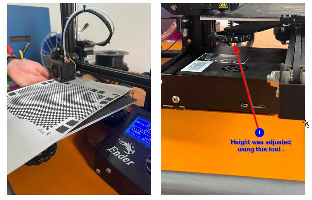
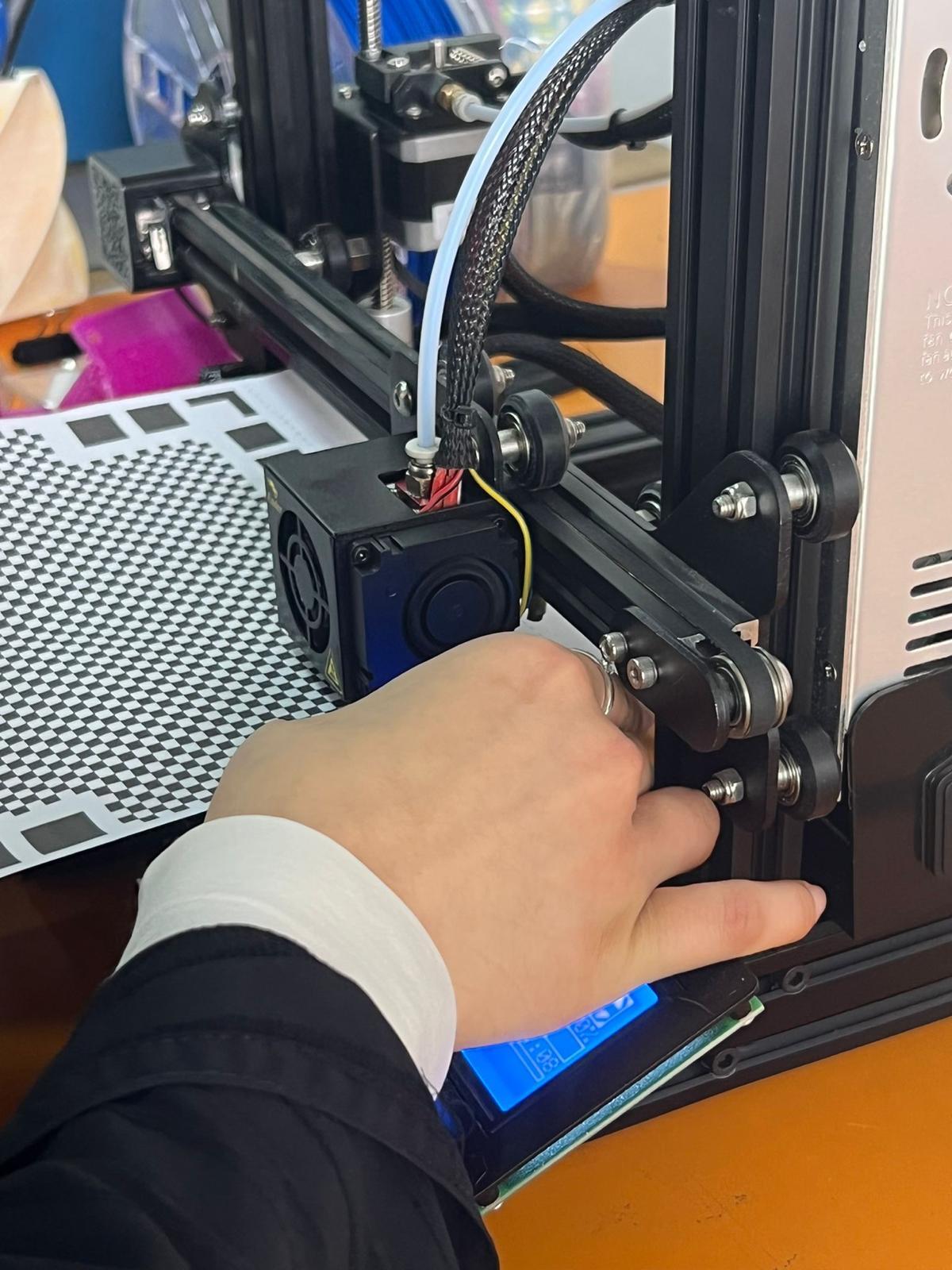
we have moved the Nozzle to the origin:
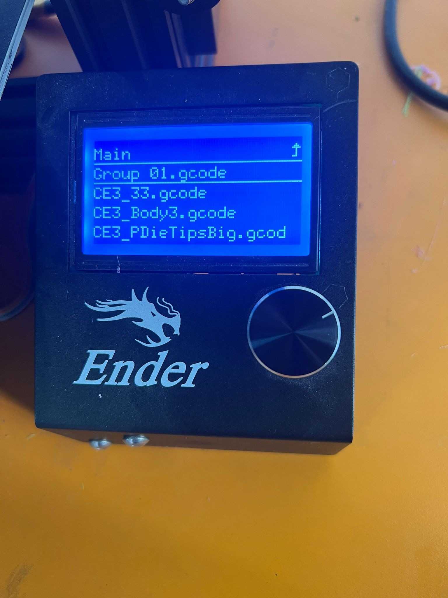
4- The memory card is then inserted to the printer.
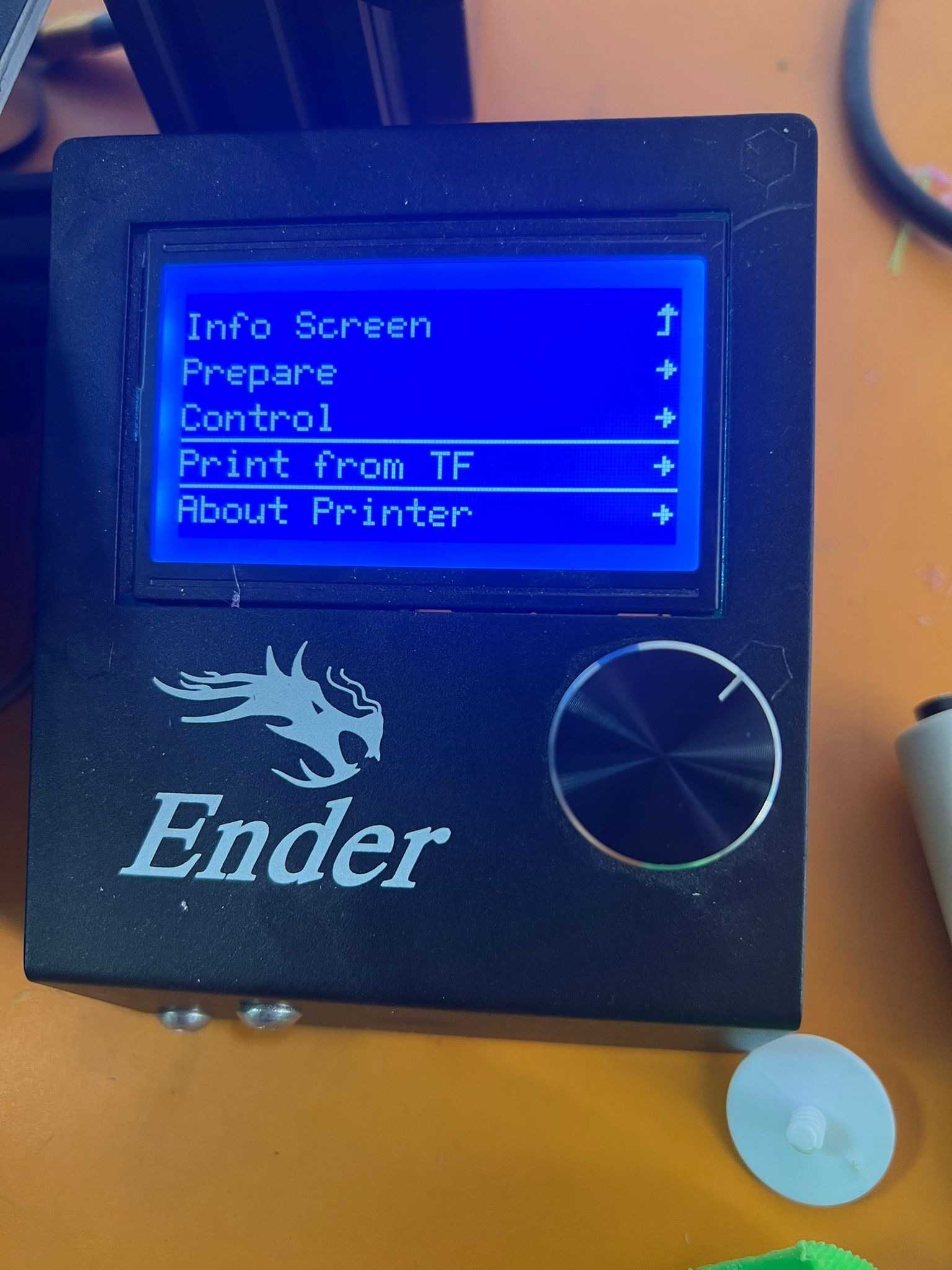
5- Finally, the “Print from TF” button was selected and the file was chosen.
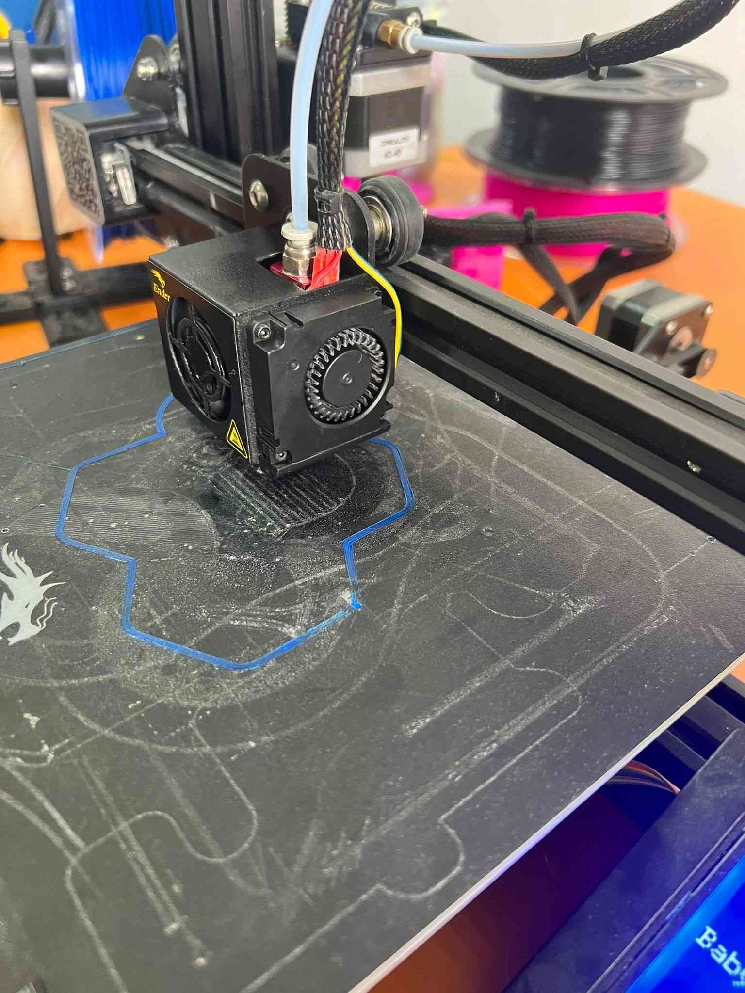
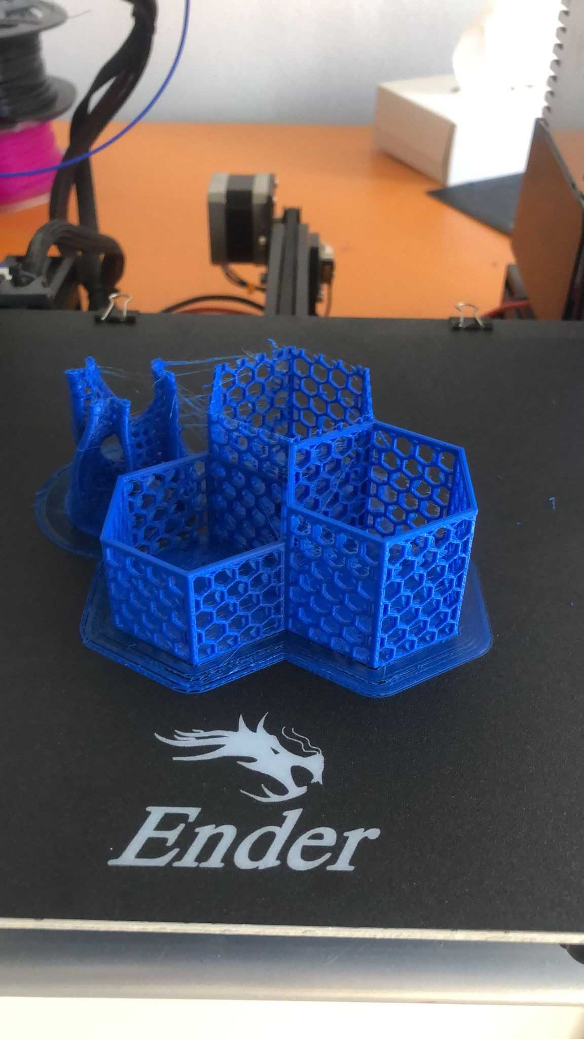
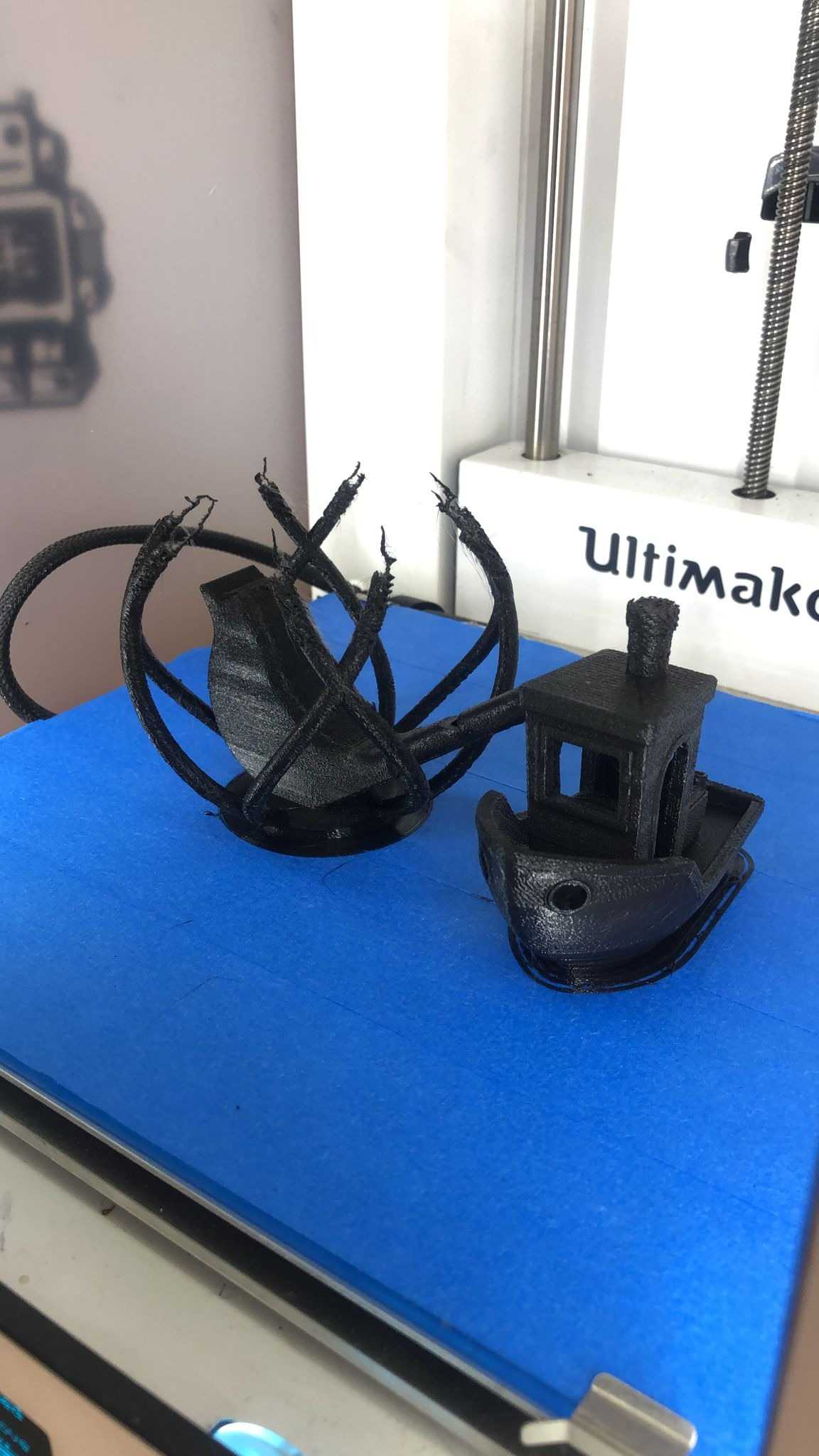
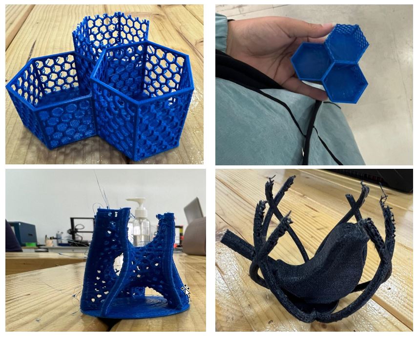
Final Results
After attending the next session we found the following results:
Individual Assignment
3D Scanning Time !
For 3d scanning, our instructor have suggested for us to download and use a phone application called “Qlone”. To improve the scanning quality we used a scanning mat and started scanning. In addition, the quality of the scanning depends also on other factors. For instance, it depends on the object material, bends, the position.
Quick Guide that I have accomplished for scanning the object:
-
Make sure that the scanning surface is straight and flat.
-
Make sure to print the mat on a non-glossy paper.
-
Place the object in the middle on the paper and move slowly around it.
-
Alternatively, you can rotate the mat instead of moving around it. However, make sure that the object stays in it origin place.
-
To achieve better results you can merge different poses of the object.
You can learn and practice more about the application through the following Qlone Tips & Practices Playlist.
Scanned Objects
To try this application I have scanned the following object.
Object 1
First Attempt:
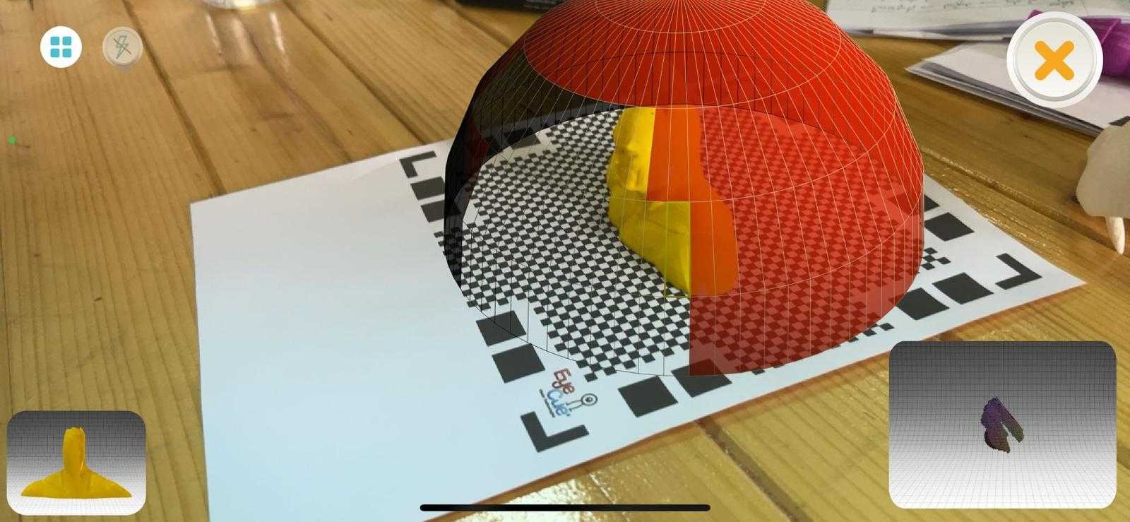
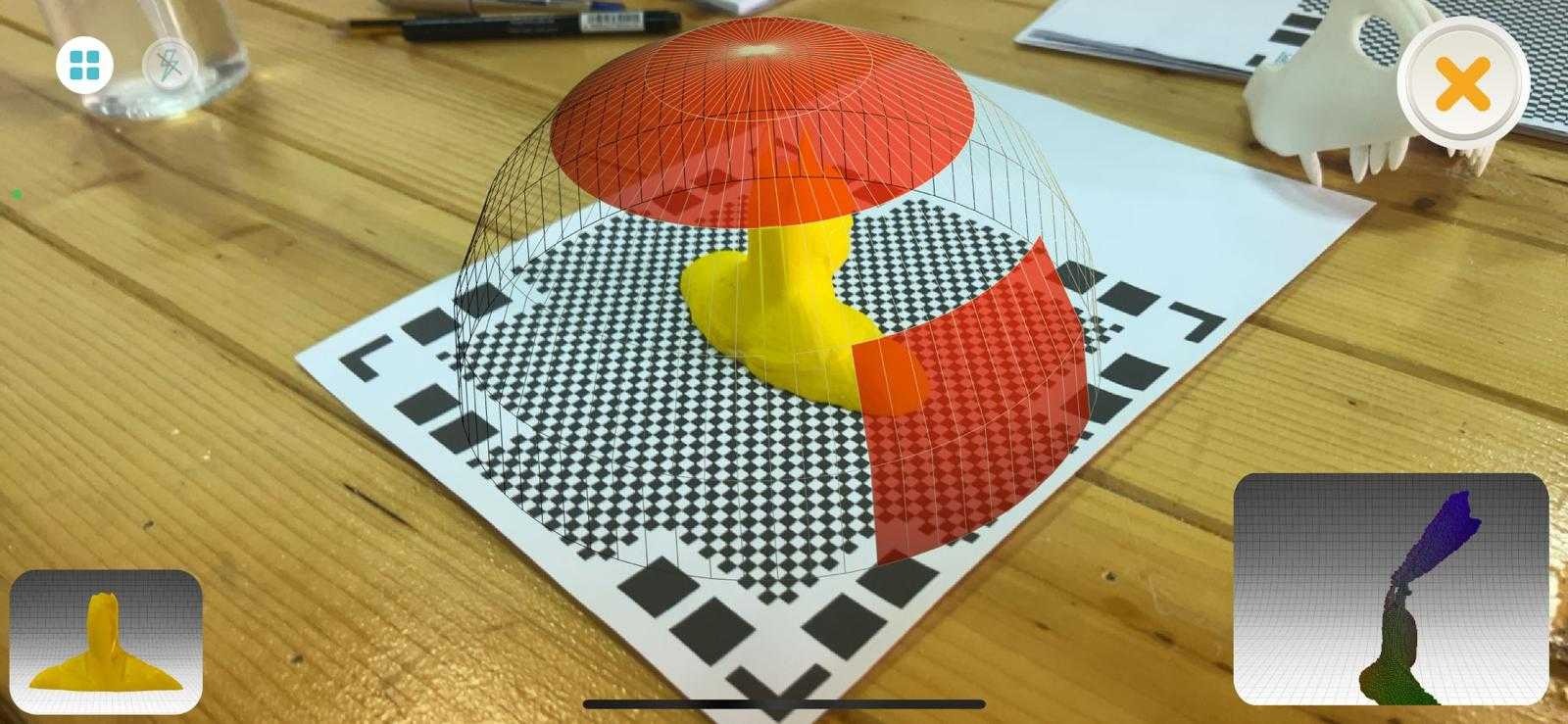
1- The Object was placed in the center of the mat as follows:
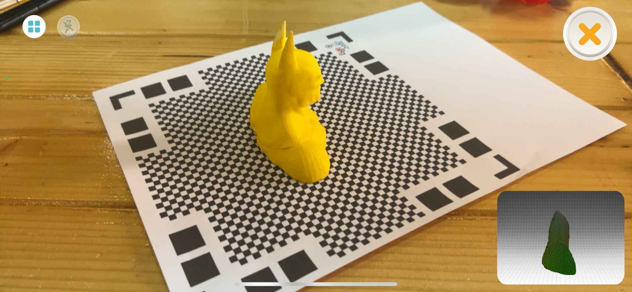
2- I rotated the mat from all sides to make sure to cover all the blue boundary. Note: when the blue boundary turn red it means that you are a bit far from the object.
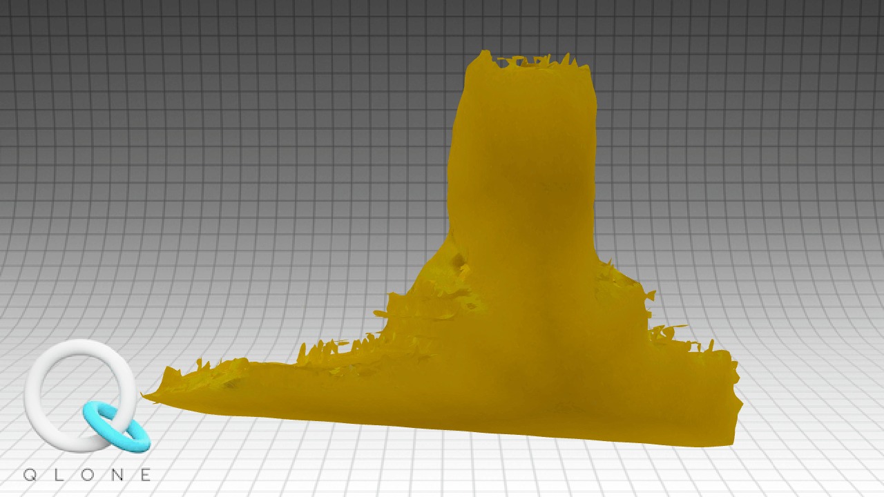
The first trial results where the following:
Second Attempt:
Here I tried to use “Merging tool” put I misused it.
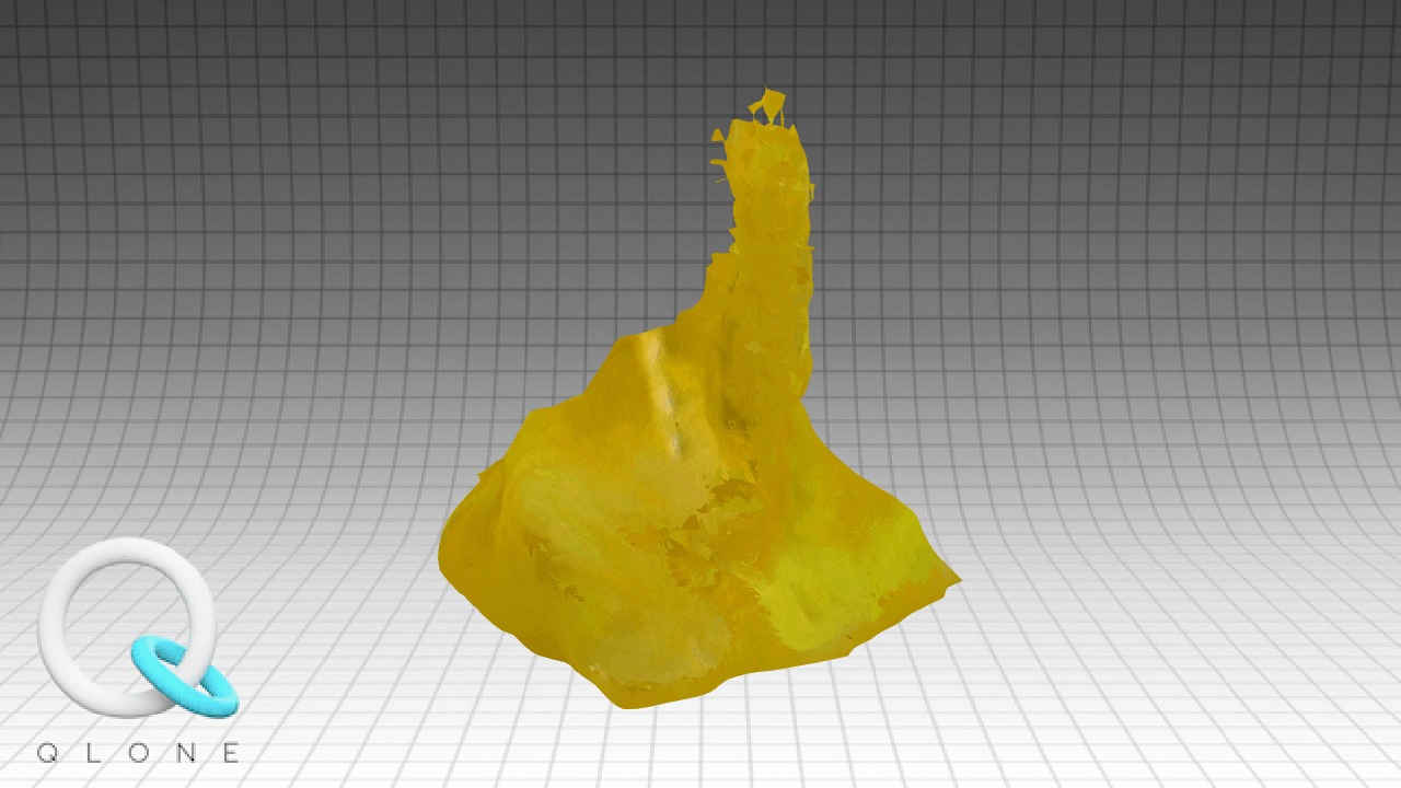
The Second trial results where the following:
Third Trial:
Here I changed the object position:
The Second trial results where the following:

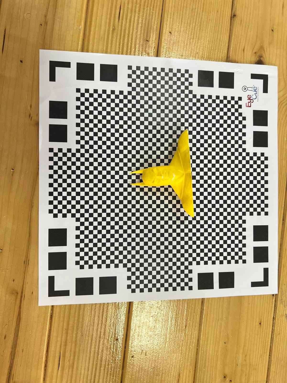
Final Trial:
To over come all the previous issue, I accomplish the following:
-
Used Larger Scanning Mat (A3 paper)
-
Change the object position and place him on his back
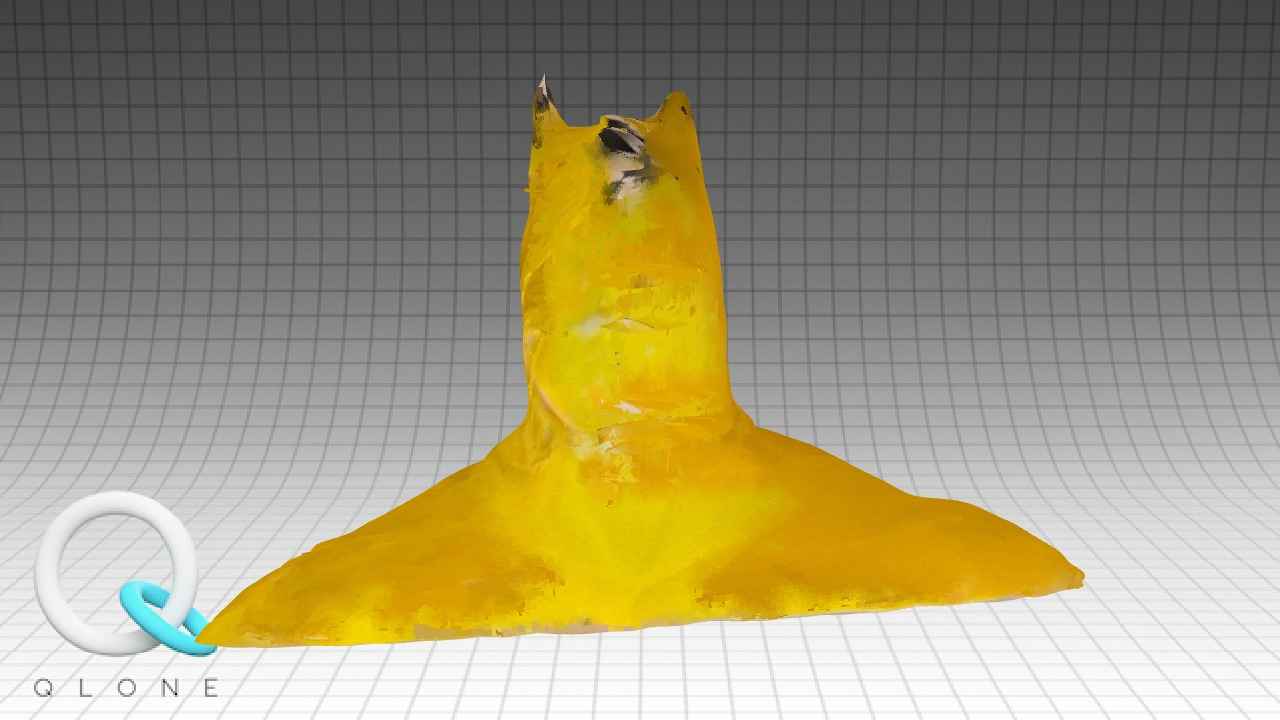
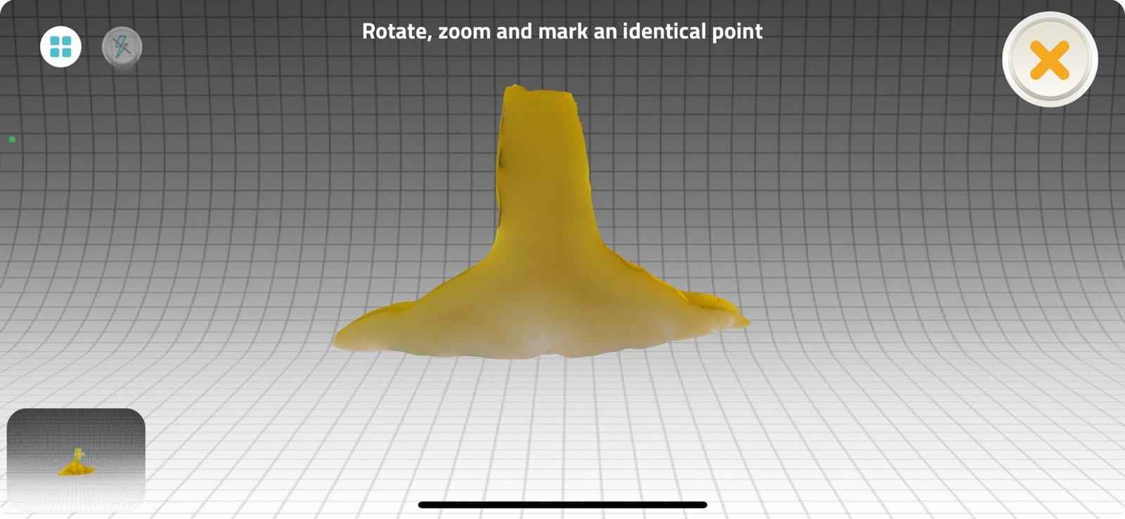
Enjoy watching the following video:

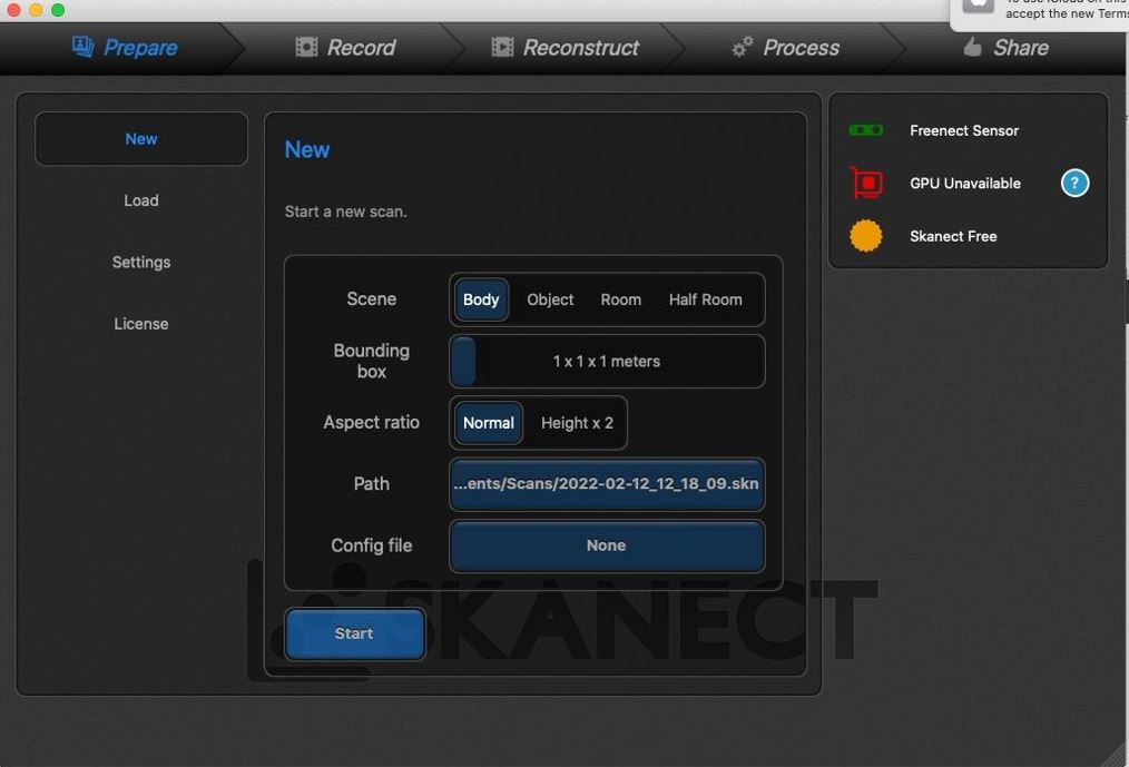
Object 2
I was so interested to scan my self using Xbox kinect and Skanect software. Xbox kinect front side is equipped with three cameras and a green LED. The central camera reads a color picture in space with a speed 30 frames per second. Continued analysis of the image under negative light background. The instructor and I did the following steps:
1- After opening the program, we have adjusted the following settings:
2- I have sat on the chair and the instructor have selected the starting angle.
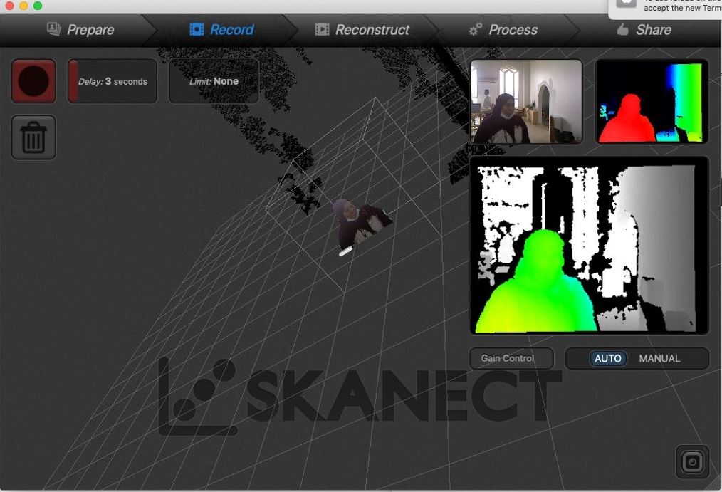
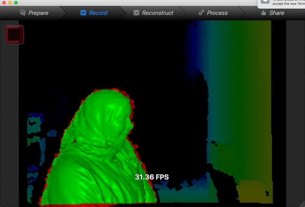
3- Then we have reconstructed the object (me)!
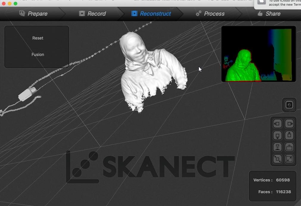
4- After finishing the scanning, we went on to the settings and fill the gap that the couldn’t reached by the green LED.
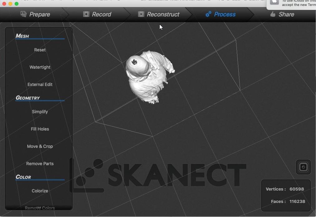

5- I was so happy with the output and honestly speaking it was such a successful experience !
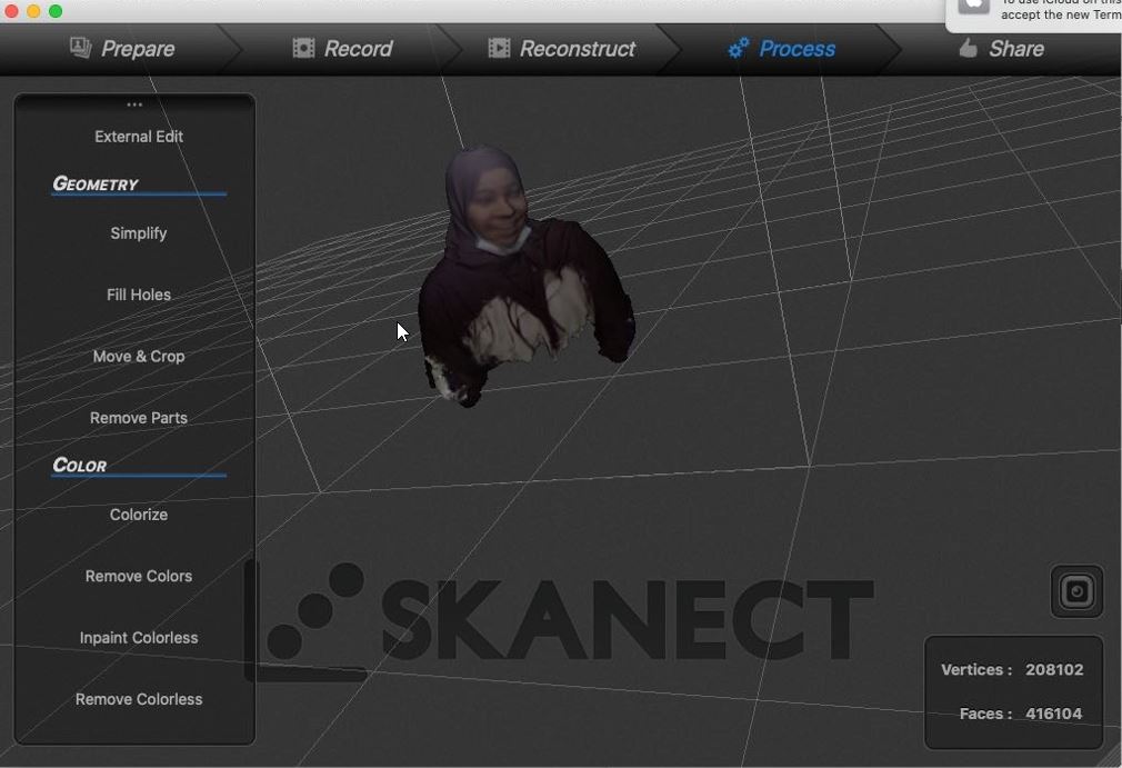
Preview Me from different sides !
3D Printing Time !
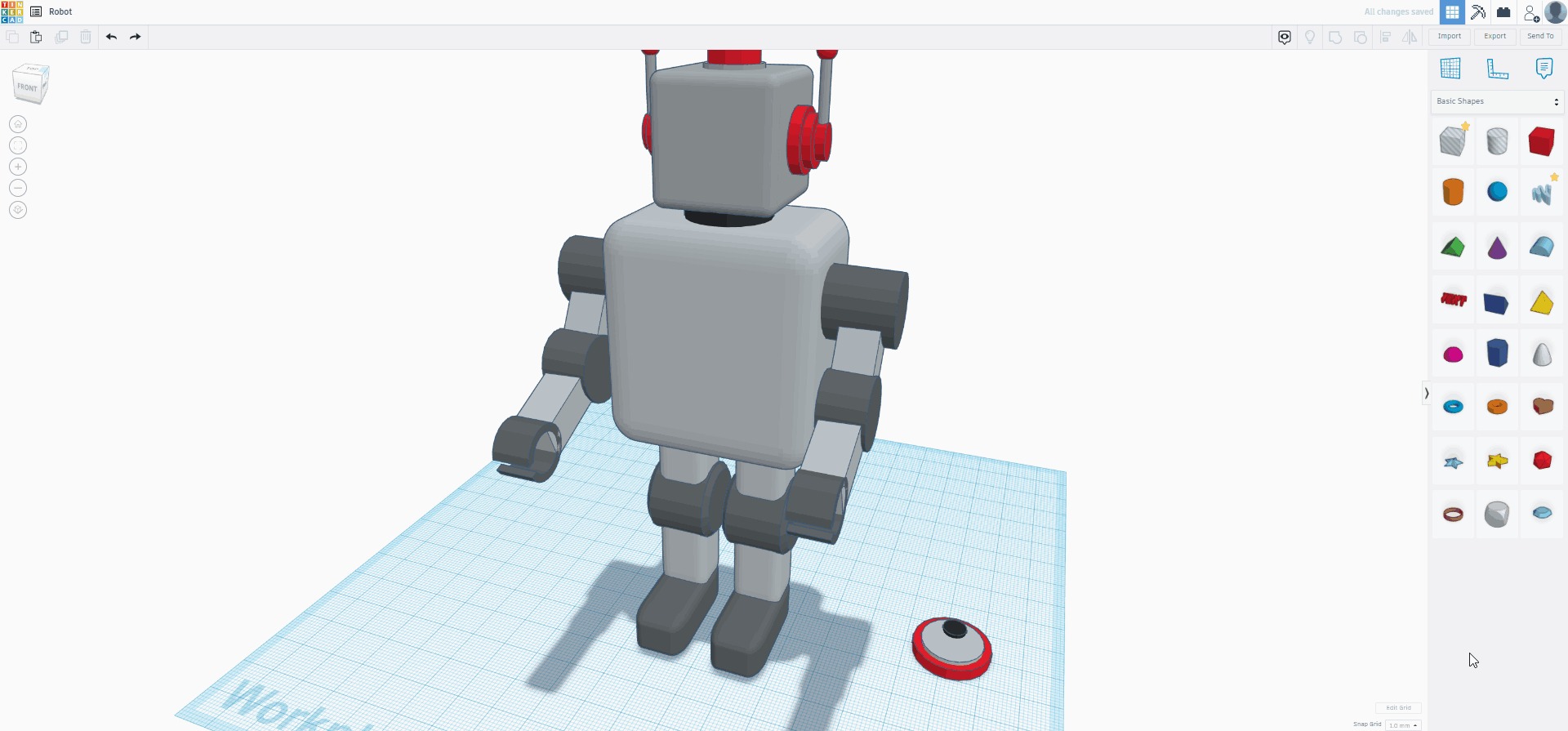
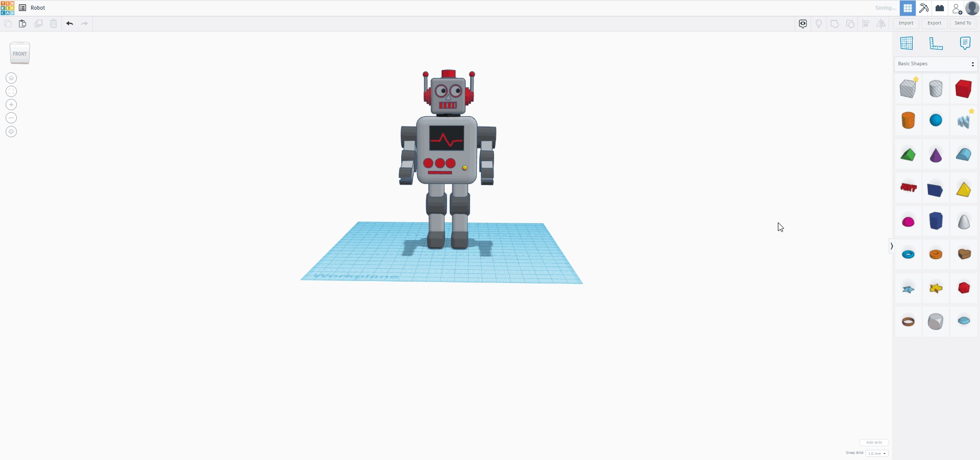
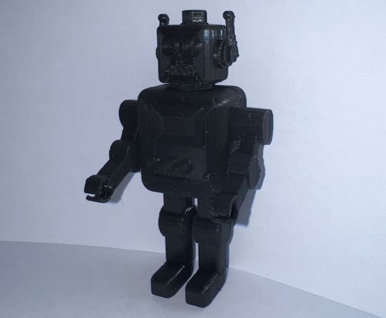
Since my childhood I always was fascinated with robots. Therefore, for my 3D design I choice to do a robot !
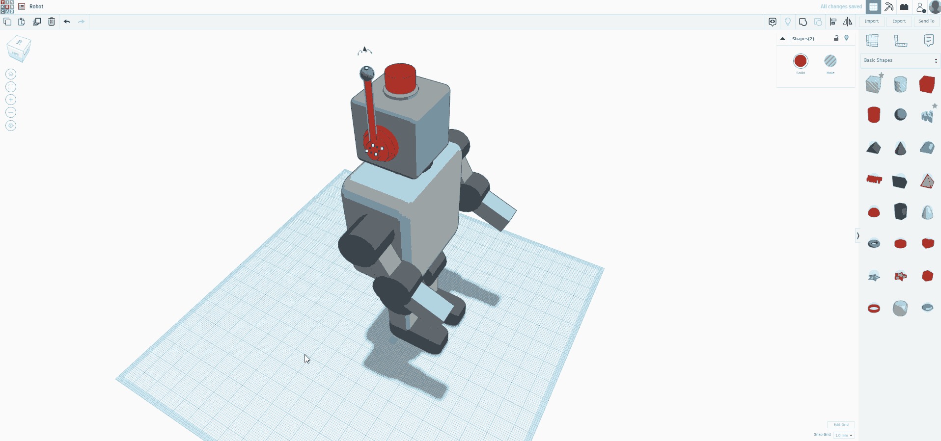
Here are some shots for the designing processes:
- This is the robot biases after using variety of squares and cylinders found in the “basic shapes” menu. Just a quick note, to make the square curve I change the “Radius” level.

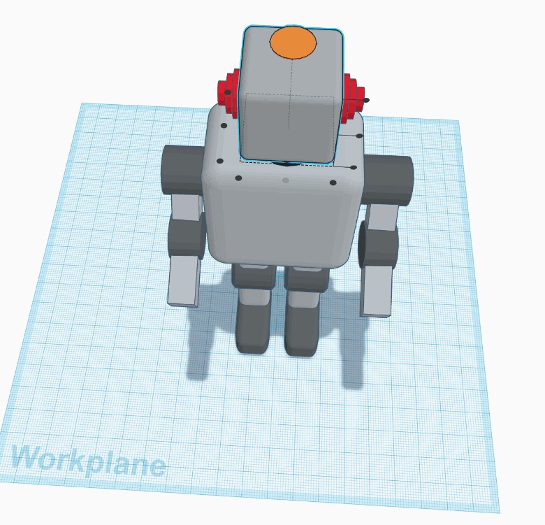
- To make the robot ears I used 3 squares as it is shown below:
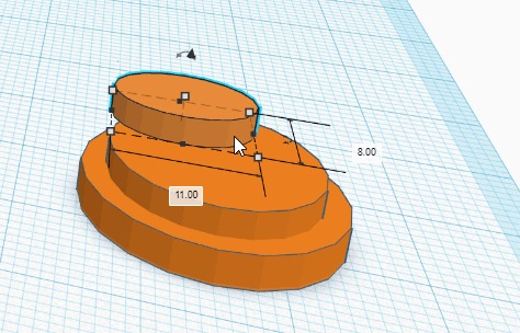
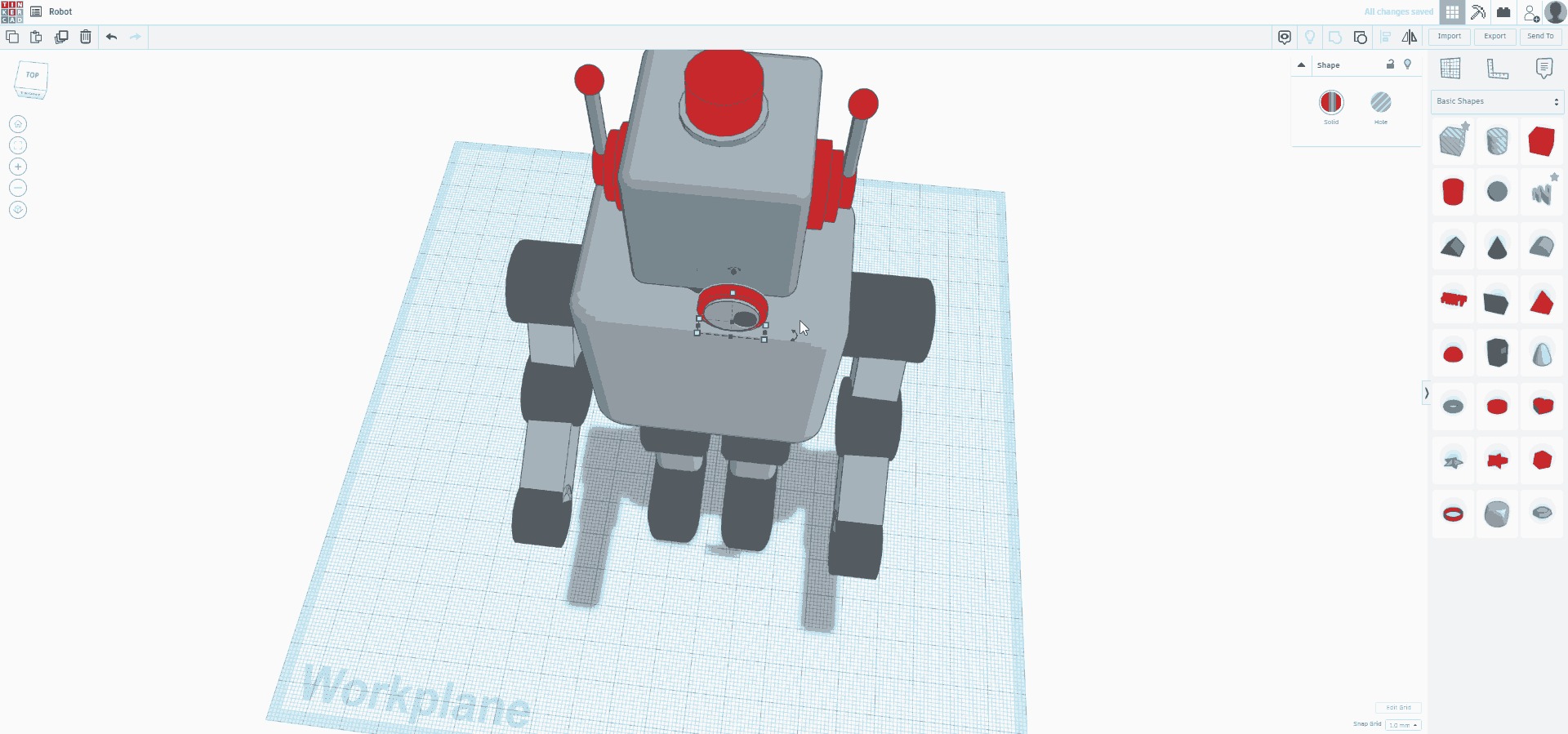
- To make the LED on top of the robot head, I have added two cylinders and “Align” tool to make it in the center as follows:
- Using a long cylinder and a sphere I ccompleted the robot ears:
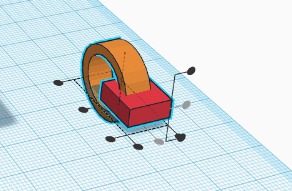
- For the hands, I used a tube and rectangle shape. I have set the rectangle as a “Hole” and use “Group” tool.
- For the robot eyes, I have used three circle, align them, group them, change its angle, and finally placed in the face:
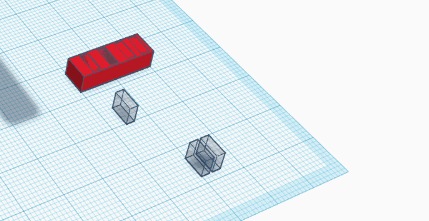
- The robot mouth was created using a big square and a small squares that are set to be as “Holes”. Then, I have grouped the shapes together:
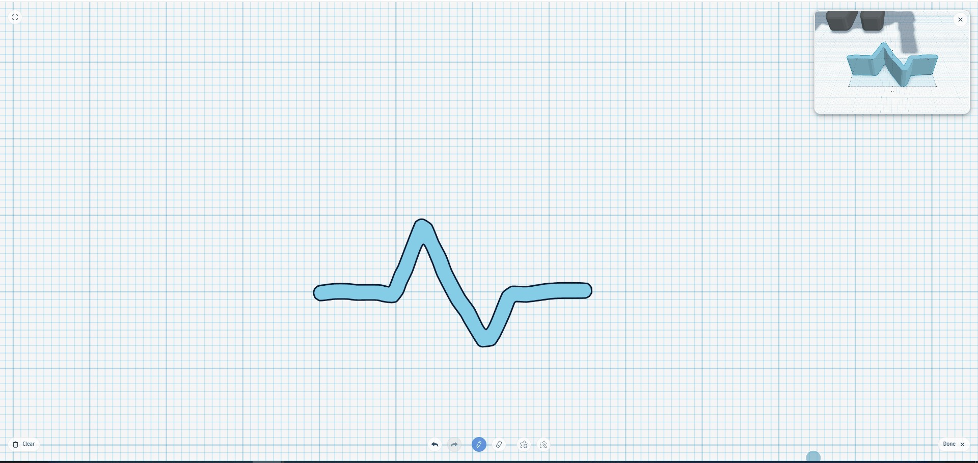
- As for the heart beating signal, I used “scribble” tool to draw on and group it to the black screen.
Final Result !!!!
Note: It could not be easily made subtractively because as it is shown above, the design have holes, curves, and too much details that would not be handled by subtractive technologies.
3D Model
Design files (in STL format):
Slicing
After completing with the design, I used again the Cura software to slice the design.
The Following steps are achieved:
- The printer type is selected:

- The design worked on have been uploaded:

- Select “Customize” from the “Standard Quality” button, then the parameters where edited as follows:
Then, the g-code have been saved to the memory card and uploaded to the printer. Finally, the printer started printing the design.
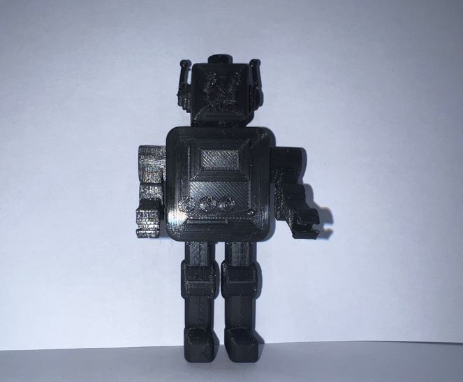
Printing Issues
We have faced some issues while printing the design, therefore, we had to printed the design 4 times.
-
For the first and second attempt, there was some maintenance in the fab lab’s electricity. Hence, the 3D Printer have shut down while printing the design.
-
For the Third attempt, the designs quality have reduced because their was some dust in the nozzle.
- After printing:
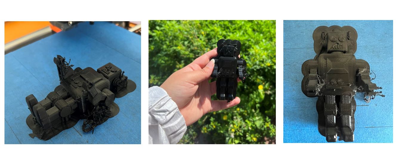
- Finally, I went and remove all the support and used sand sheets to smoothen the design:
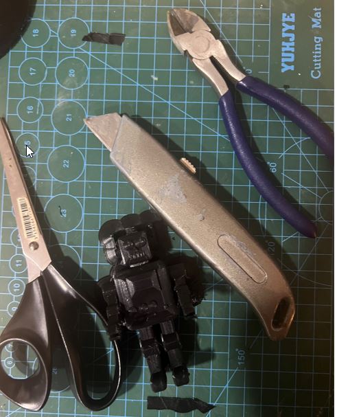
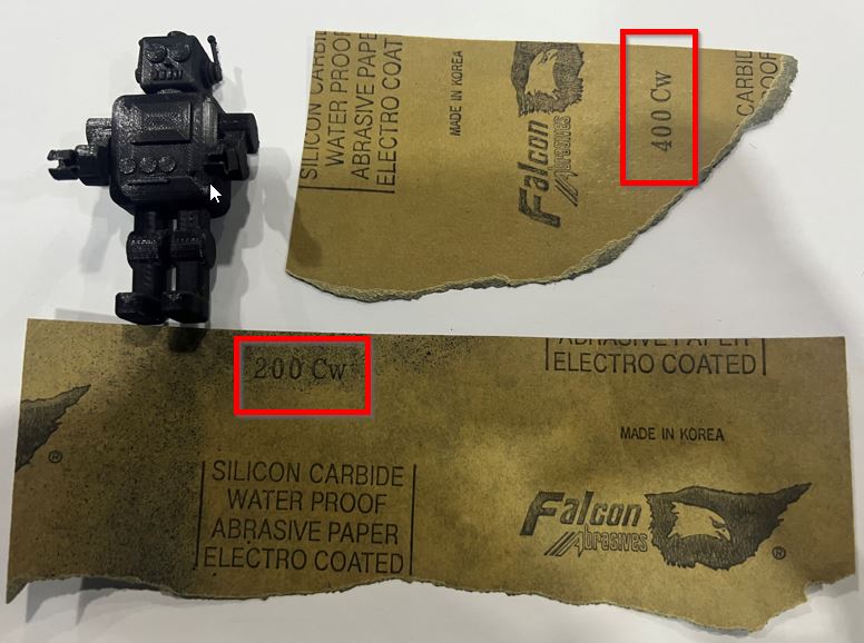
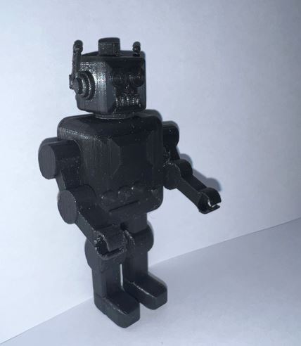
Thus, let me now show you the final design in the following hero shot.
Hero shots
Extra Bonus Video !
Resources
Thank you for reading !