4. Embedded programming
Week Objectives:
As a Group:
-
Search for different types of microcontrollers boards and compare between them.
-
Search for different programming languages, compare between them and how many can you use to program the same microcontrollers.
As an Individual:
-
Read the datasheet for the microcontroller board you are programming
-
Program the board you have to do something, with as many different programming languages and programming environments as possible. (two at least)
==============================================================================
Introduction
During this week, we have covered “Embedded programming” concept.
Embedded Programming
Embedded programming is a specific type of programming that supports the creation of consumer facing or business facing devices that don’t operate on traditional operating systems the way that full-scale laptop computers and mobile devices do. The idea of embedded programming is part of what drives the evolution of the digital appliances and equipment in today’s IT markets.
Arduino IDE
The open-source Arduino Software (IDE) makes it easy to write code and upload it to the board. This software can be used with any Arduino board. It is used for writing code, compiling the code to check if any errors are there and uploading the code to the Arduino.
================================================================================
Group Assignment
For this week as a group we were asked to research about:
- Types of microcontrollers boards
- Different programming languages
Our instructor have divided us to two groups to do an extensive research and share it with the other group.
Part 1
My group was responsible for the different microcontrollers boards types research. To speed up the team work process we have utilize google docs. Below you will find our work:


Sources:
Part 2
As for the different programming languages section, below a link for the group work:
================================================================================
Individual Assignment
Microcontroller Datasheet
Datasheets are more often used as reference than as detailed manual. This means that you have to research many concepts and features of a component outside the datasheet, for example by doing a hands-on lab evaluation.
Here you will find the Adafruit Bluefruit Sense feather Microcontroller Datasheet .
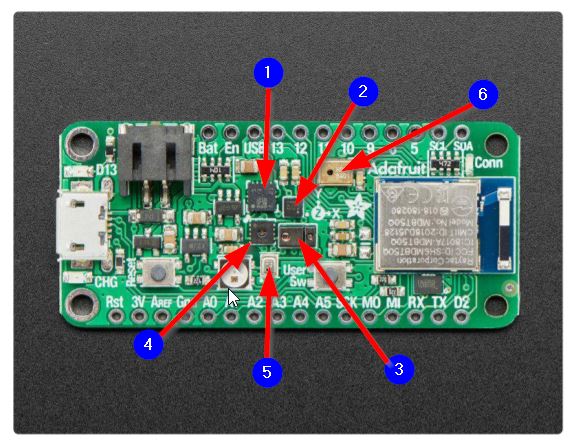
I collected the following data from the Adafruit Bluefruit Sense feather Microcontroller Datasheet:
-
The Feather is an ‘all-in-one’ Arduinocompatible + Bluetooth Low Energy with built in USB plus battery charging.
-
Pin 13 red LED for general purpose blinking, Blue LED for general purpose connection status, NeoPixel for colorful feedback.
-
Safety: In order to avoid damaging the sensitive analog circuitry, AREF must be equal to or lower than VDD (3.3V)!
-
Analog Pins: there is 6 available analog inputs (A0 .. A5) can be configured to generate 8, 10 or 12-bit data (or 14-bits with over-sampling), at speeds up to 200kHz
-
Any other sensors as long as there is not an I2C address collision.
Multiple sensors are available in the microcontroller as follows:
-
The microprocessor contains Gyro + Accel: LSM6DS33. This sensor is a 6-DoF IMU accelerometer + gyroscope. The 3-axis accelerometer, can tell you which direction is down towards the Earth (by measuring gravity) or how fast the Feather Sense is accelerating in 3D space. The 3-axis gyroscope that can measure spin and twist.
-
It also contains Magnetometer: LIS3MDL this Sense the magnetic fields that surround us with this handy triple-axis magnetometer (compass) module.
-
There is an embedded Light + Gesture + Proximity:APDS9960. This detect simple gestures (left to right, right to left, up to down, down to up are currently supported), return the amount of red, blue, green, and clear light, or return how close an object is to the front of the sensor
-
Humidity: SHT30 - This sensor has an excellent ±2% relative humidity and ±0.5°C accuracy for most uses.
-
Temp + Pressure: BMP280 - This sensor is a precision sensing solution for measuring barometric pressure with ±1 hPa absolute accuracy, and temperature with ±1.0°C ©Adafruit Industries Page 18 of 186 accuracy.
-
PDM Microphone sound sensor: MP34DT01-M - PDM sound sensor.
Two buttons are available in the Microcontroller as follows:
1- Reset button: Press once to reset. Quickly press twice to enter the bootloader.
2- User button - The button on the right is both usable by the bootloader and user controllable.
The datasheet contains also much more does, set up guidance for sensors and the other parts.
Board Programming
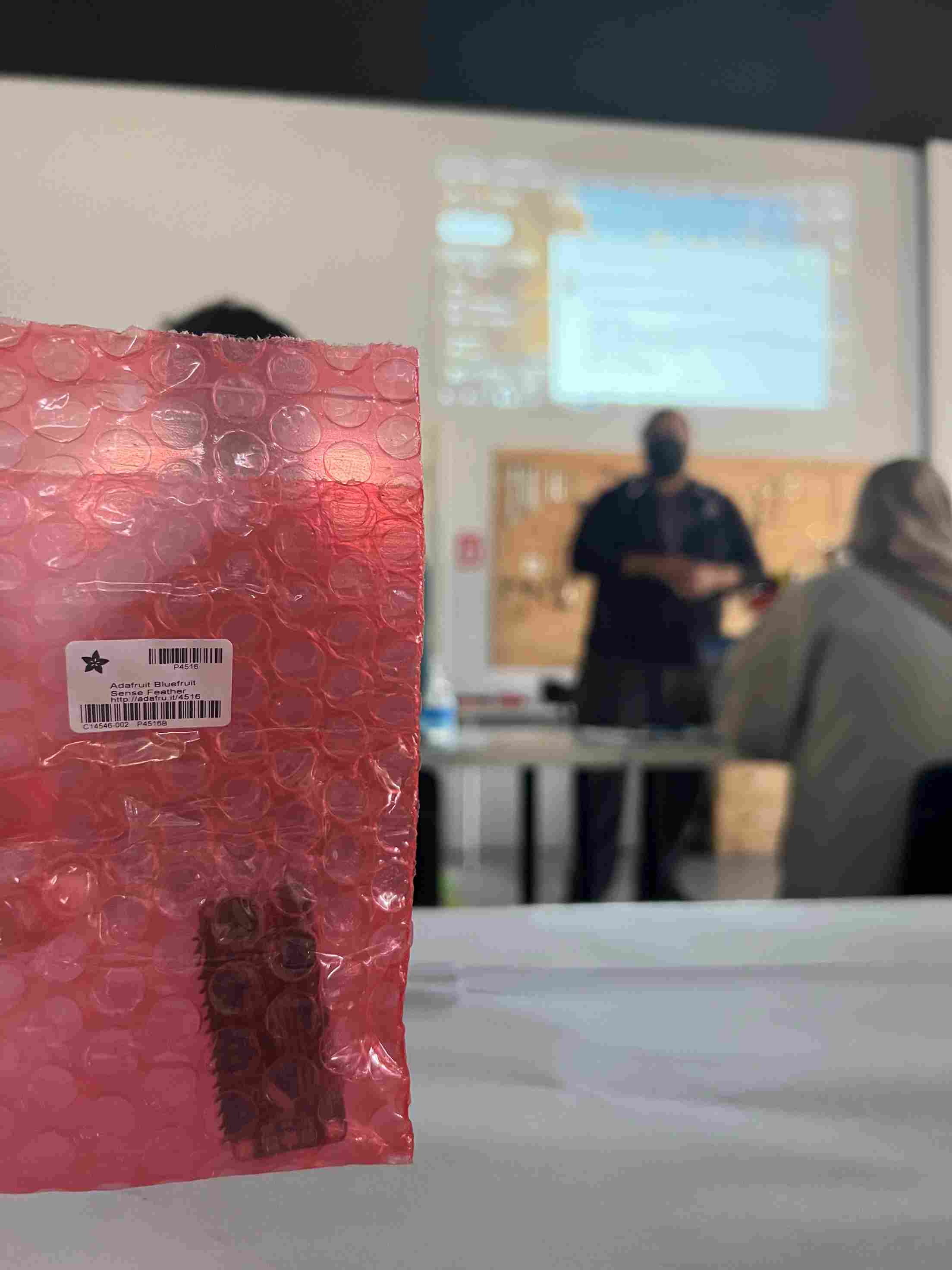
we were given “Adafruit Bluefruit Sense feather” and a data cable.
Testing Phase
To first test this microcontroller we accomplished the following steps in the first class:
1- Installing Arduino IDE 1.8.19 software. As following:
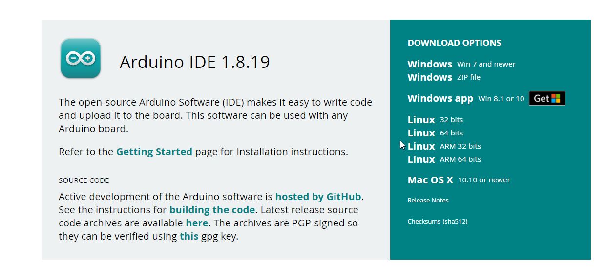
2- Then, we went on setting up the Adafruit Bluefruit Sense feather in the Arduino IDE by going through the steps mentioned in the following link:
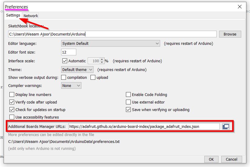
We first add https://adafruit.github.io/arduino-board-index/package_adafruit_index.json as an ‘Additional Board Manager URL’ from the Preference button under the file menu bar.
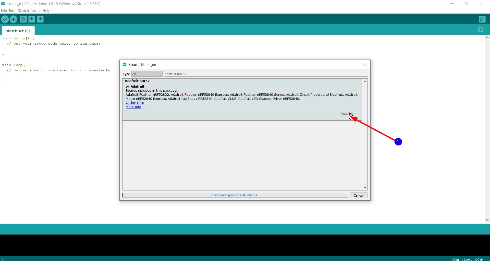
Then, the ‘Adafruit nRF52 by Adafruit’ was installed from Boards Manager option from the Tools -> Board menu.
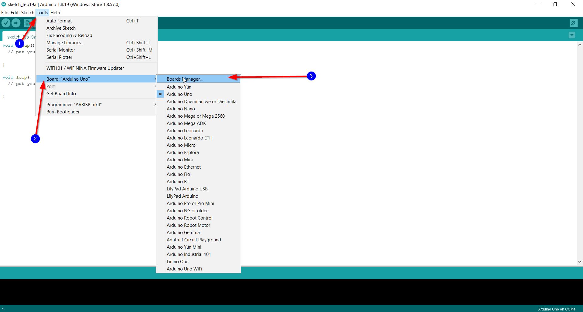
Finally, we can know easily select ‘Adafruit nRF52 by Adafruit’ to be the board:
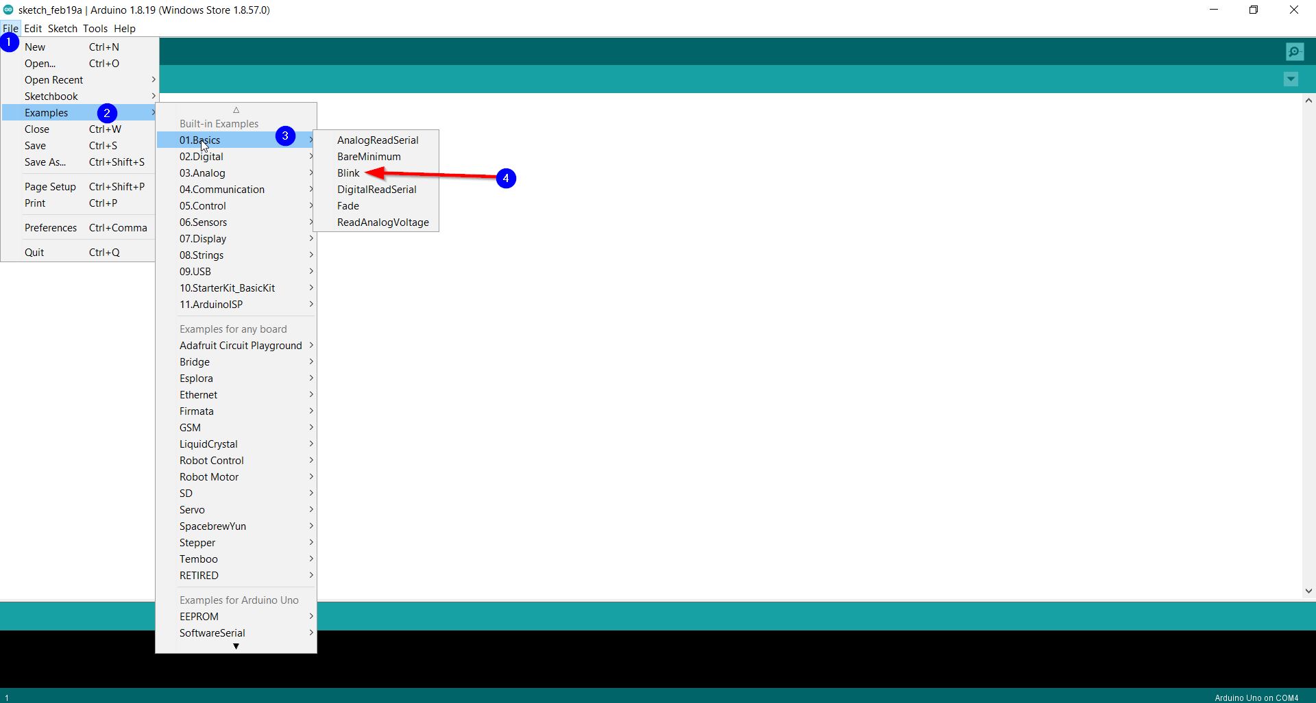
3- To test the software and Adafruit nRF52 by Adafruit fuctionality we went and tried the “Blink” code example founded from files -> examples -> Basics -> Blink. As follows:
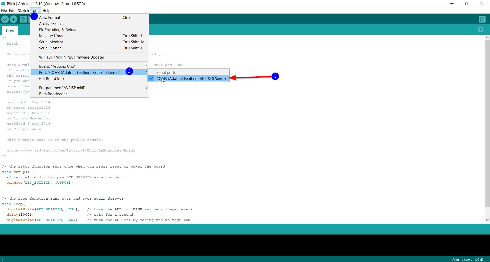
Here after we connected the Adafruit nRF52 by a data cable and upload the code:

The output was as follows:
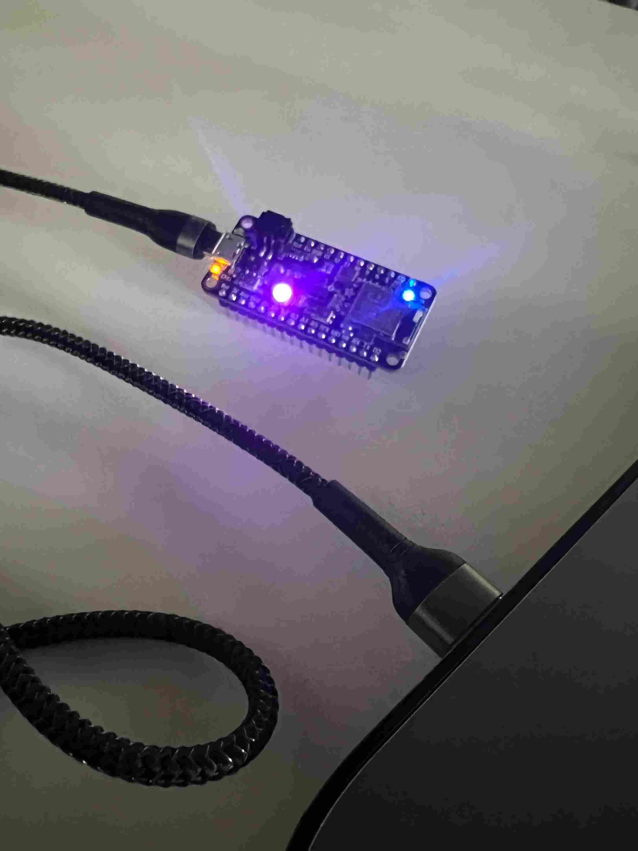
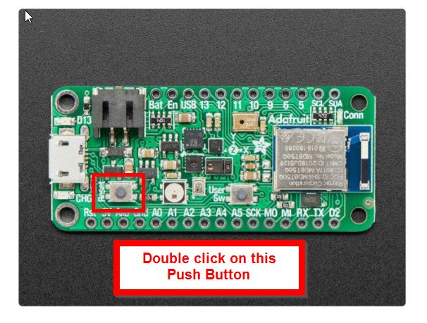
Note: Make sure to double click on the following push button before you load the program:
Blocks Coding Language
To test different programing languages, I used “Tickedcad” online website since it have blocking code technique. The following steps was accomplished
1- “New Circuit” button was selected.
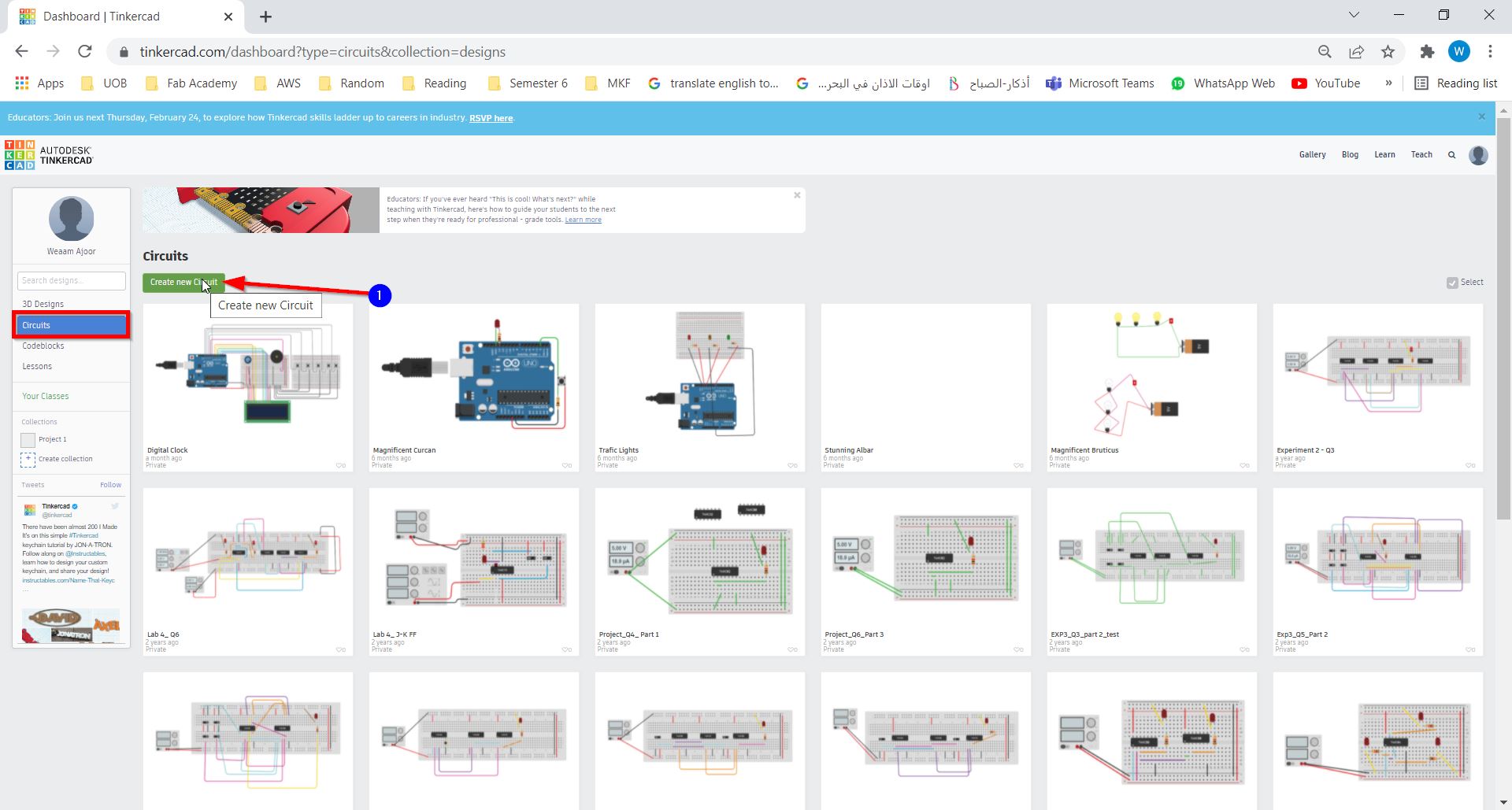
2-Arduino UNO R3 was selected from the component bar.
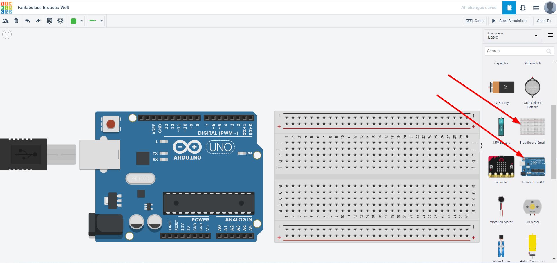
3- Then the “Code” button was chosen and “Blocks” mode was set.
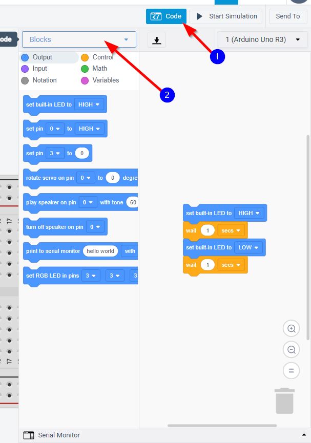
Note: By default the code that will appear is for the LED Blinking.
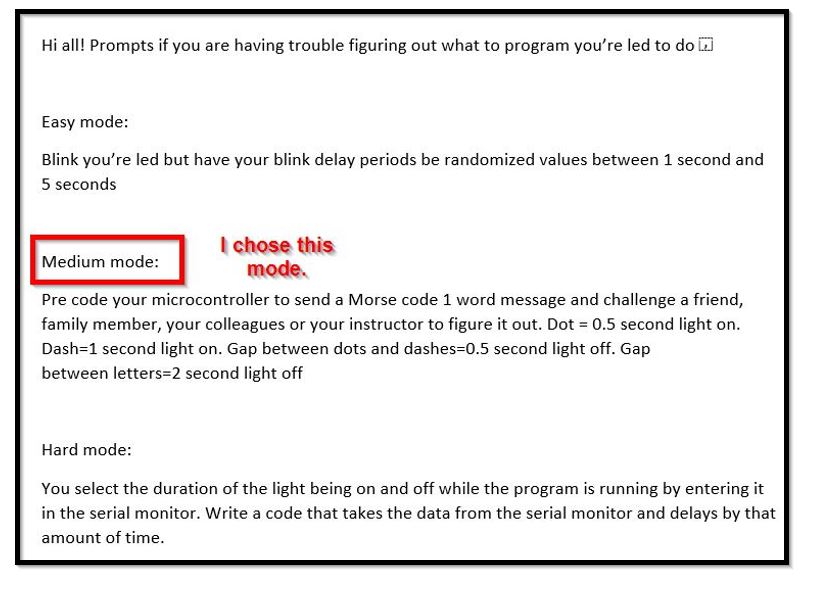
Then, the instructor gave us a challenge to convert our names to Morse code and use blocks code to make the LED to turn on and off.
What is Morse Code ?
Morse code refer to the method used in telecommunication to encode text characters as standardized sequences of two different signal durations, called dots and dashes.
Turns an LED on :
-For One second if it’s dash sign ( - )
-For half second if it’s Dot sign ( . )
Turn off the LED if :
-There is a space between one letter for 0.25 seconds.
-There is a space between two letters for two seconds.
Steps:
1- I used the following test to Morse code convertor

2- The following block code was achieved:
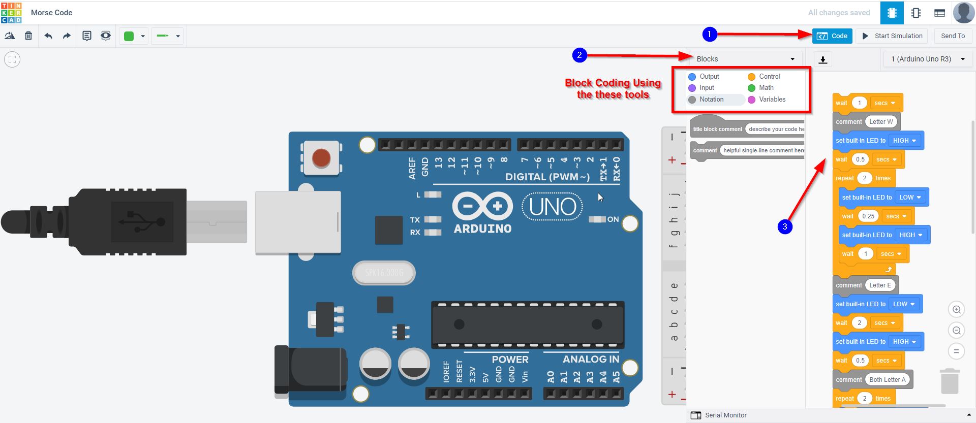
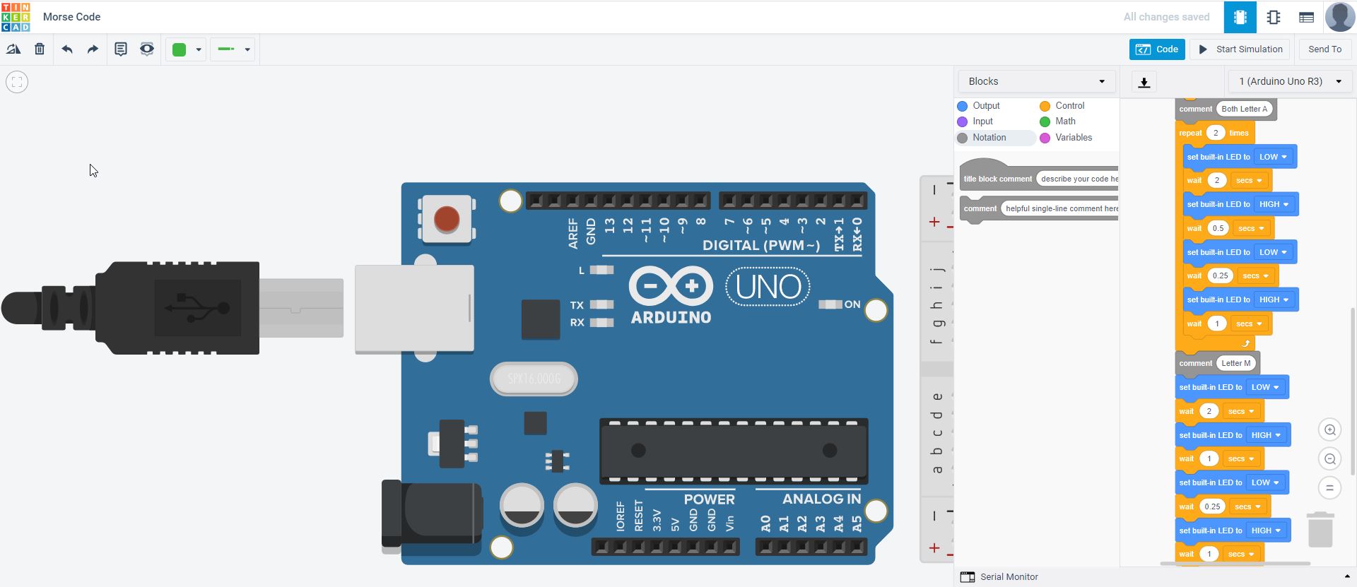
You can run the simulation and view my name in Morse code !
C/C++ programming Language
To further develop our programming skills, the instructor have displayed the following challenges:
With the same following rules:
Turns an LED on :
-For One second if it’s dash sign ( - )
-For half second if it’s Dot sign ( . )
Turn off the LED if :
-There is a space between one letter for 0.25 seconds.
-There is a space between two letters for two seconds.
I tried again to write a code of my name (in Morse code format).
My Code
Here is my name in Morse Code !!!
/*
 Morse code & Blinking LED

  Most Arduinos have an on-board LED you can control. On the UNO, MEGA and ZERO it is attached to digital pin 13, on MKR1000 on pin 6. LED_BUILTIN is set to
  the correct LED pin independent of which board is used.

  Morse code refer to the method used in telecommunication to encode text characters as standardized sequences of two different signal durations, called dots and dashes.

  Turns an LED on :
  - For One second if it's dash sign ( - )
  - For half second if it's Dot sign  ( . )

  Turn off the LED if :
  - There is a space between one letter for 0.25 seconds.
  - There is a space between two letters for two seconds.
*/


// the setup function runs once when you press reset or power the board

void setup() {
  // initialize digital pin LED_BUILTIN as an output.
  pinMode(LED_BUILTIN, OUTPUT);
}

// the loop function runs over and over again forever
void loop() {
  delay(1000);                       // To create repetition

  // Letter W
  digitalWrite(LED_BUILTIN, HIGH);   // turn the LED on (HIGH is the voltage level)
  delay(500);                        // wait for 0.5 second

  digitalWrite(LED_BUILTIN, LOW);    // turn the LED off for the space
  delay(250);                        // wait for 0.25 second

  digitalWrite(LED_BUILTIN, HIGH);   // turn the LED on for the dash
  delay(1000);                       // wait for 1 second

  digitalWrite(LED_BUILTIN, LOW);    // turn the LED off for the space
  delay(250);                        // wait for 0.25 second

  digitalWrite(LED_BUILTIN, HIGH);   // turn the LED for the dash
  delay(1000);                       // wait for 1 second

  // Letter E

  digitalWrite(LED_BUILTIN, LOW);    // turn the LED off for the space
  delay(2000);                       // wait for 2 second

  digitalWrite(LED_BUILTIN, HIGH);   // turn the LED for the dot
  delay(500);                        // wait for 0.5 second

  // Letter A

  digitalWrite(LED_BUILTIN, LOW);    // turn the LED off for the space
  delay(2000);                       // wait for 2 second

  digitalWrite(LED_BUILTIN, HIGH);   // turn the LED for the dot
  delay(500);                        // wait for 0.5 second

  digitalWrite(LED_BUILTIN, LOW);    // turn the LED off for the space
  delay(250);                        // wait for 0.25 second

  digitalWrite(LED_BUILTIN, HIGH);   // turn the LED for the dash
  delay(1000);                       // wait for 1 second

  // Letter M

  digitalWrite(LED_BUILTIN, LOW);    // turn the LED off for the space
  delay(2000);                       // wait for 2 second

  digitalWrite(LED_BUILTIN, HIGH);   // turn the LED for the dash
  delay(1000);                       // wait for 1 second

  digitalWrite(LED_BUILTIN, LOW);    // turn the LED off for the space
  delay(250);                        // wait for 0.25 second

  digitalWrite(LED_BUILTIN, HIGH);   // turn the LED for the dash
  delay(1000);                       // wait for 1 second
}
Hero Video
Resources
Thank you for reading !