6. Large format CNC (computer controlled Machining)
Week Objectives:
As a Group:
-
Test runout, alignment, speeds, feeds, and toolpaths for your machine
-
Document your work (in a group or individually)
As a Individual:
- Make (Design+mill + Assemble) something big.
Introduction
During this week, we have learnt how to use CNC machine and its technical work.
What is CNC machine ?
Computer Numerical Control (CNC) machining is a manufacturing process in which pre-programmed computer software dictates the movement of factory tools and machinery. The process can be used to control a range of complex machinery, from grinders and lathes to mills and CNC routers. With CNC machining, three-dimensional cutting tasks can be accomplished in a single set of prompts.
CNC machines can have several axes of movement, and these movements can be either linear or rotary. Many machines have both types. Cutout machines like lasers or waterjets generally have just two linear axes, X and Y. Milling machines usually have at least three, X, Y, and Z, and can have more rotary axes. A five axis milling machine is one that has three linear axes and two rotary, allowing the cutter to operate in a full 180º hemisphere and sometimes more. Five axis lasers exist as well. A robot arm might have more than five axes.
Group Assignment
For this week, as group assignment we learnt more about the CNC machine available. In addition, we have tested runout, alignment, speeds, feeds, and toolpaths for our machine. Therefore, below you will find an overlook on what we did in the fab lab:
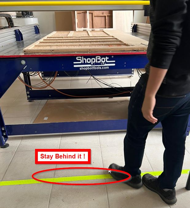
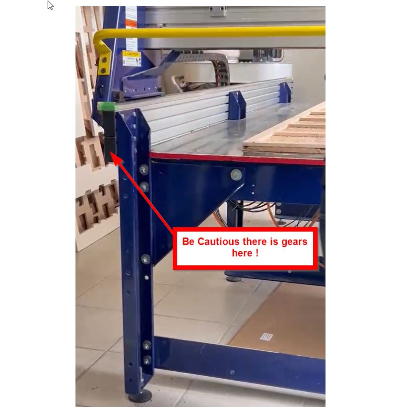
Safety Guidelines
1- Remove your accessories such as the clock watch and make sure to wear a safety glasses.

2- Leave a space and stop behind the line.
3- Since the machine moves all the sides, there is gears on the right-hand side and left-hand side. So to prevent your clothes to be stack in it please make sure to keep an enough space while moving around the machine sides.
4- If by accident something happen, there is three ways to stop the CNC machine. As follows:
- Pressing the following “Stop” pushbutton:
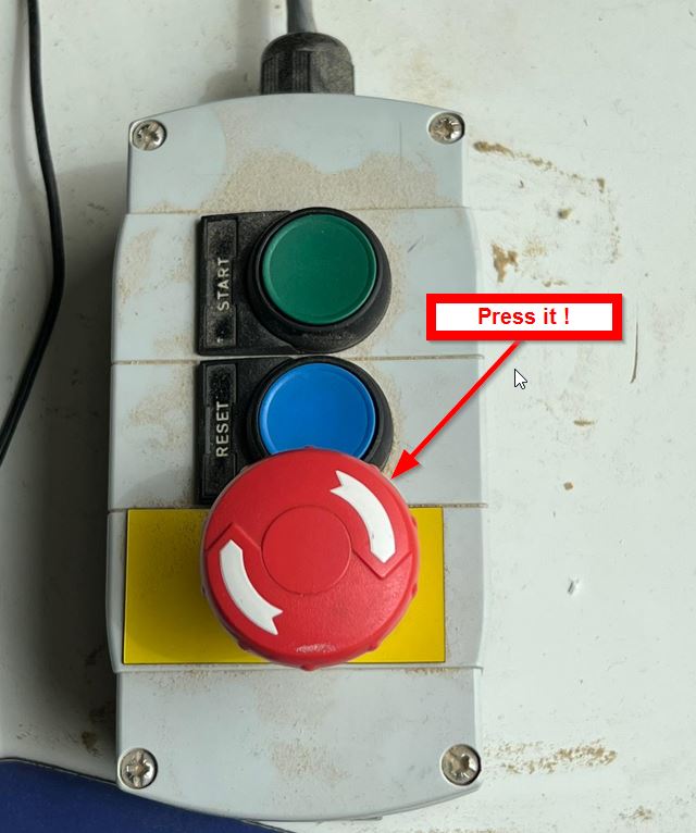
- Pressing the red button from the right-hand side of the machine founded here:
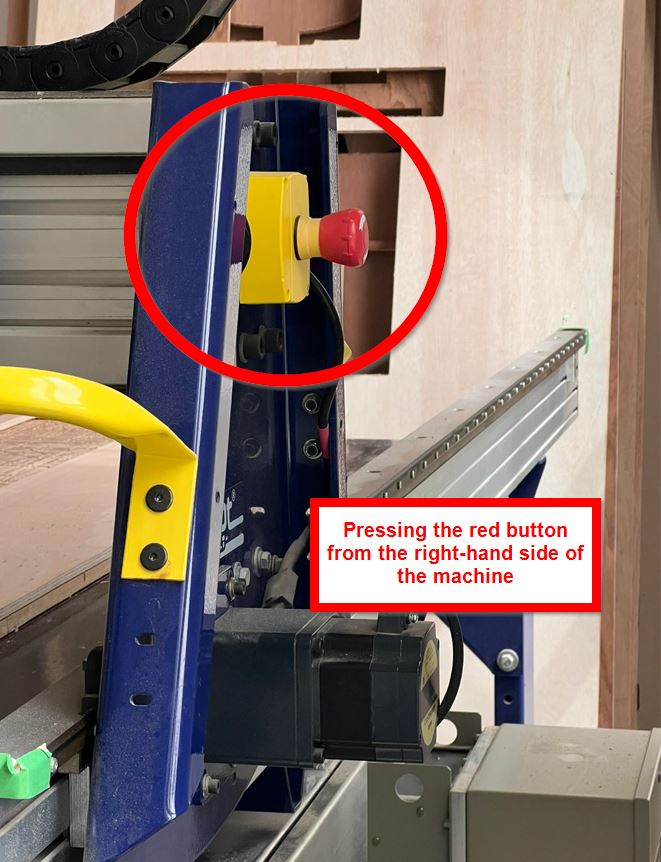
- Close the CNC machine from the bulk cable.
Setting-Up the toolpath
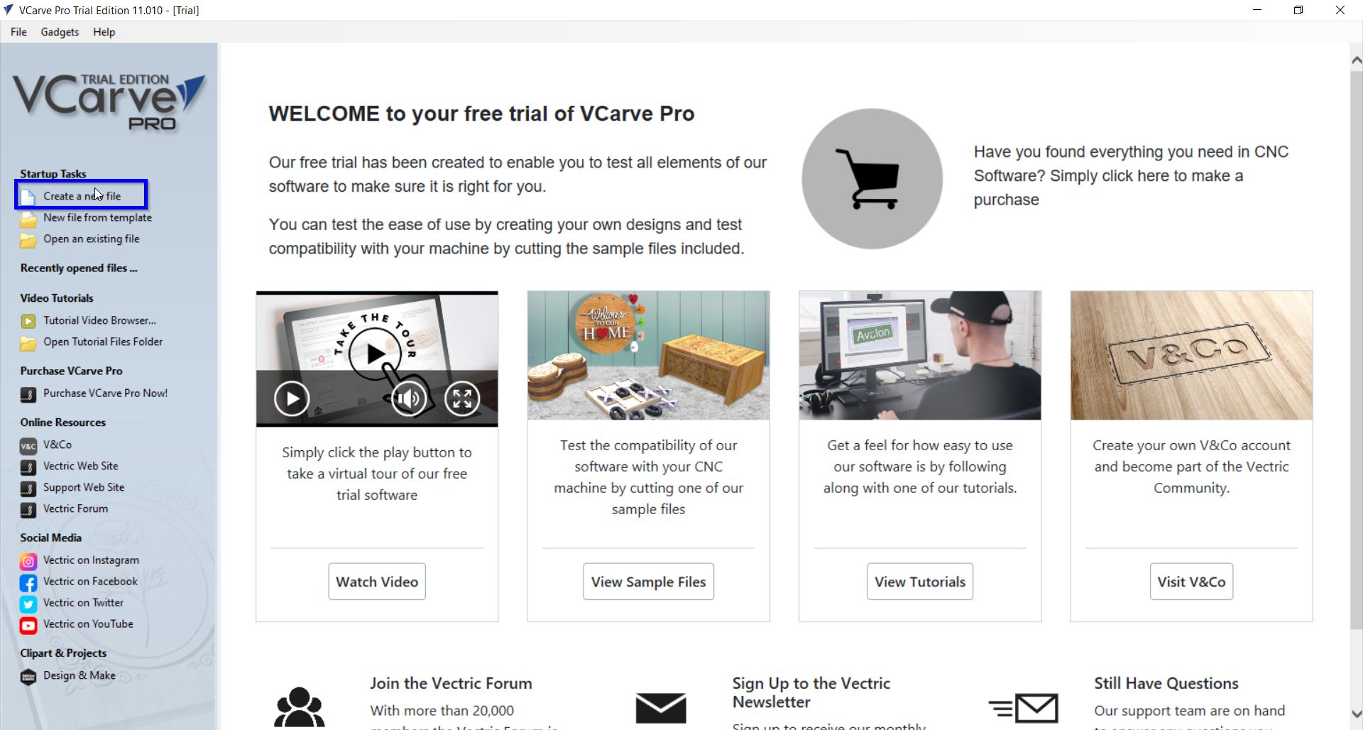
We were requested to download the VCarve Pro Trial to configure the design before sending them to CNC machine.
Then, we did couple of steps to test and learn how to use the software. As follows:
1- Select “Create a new file” button:
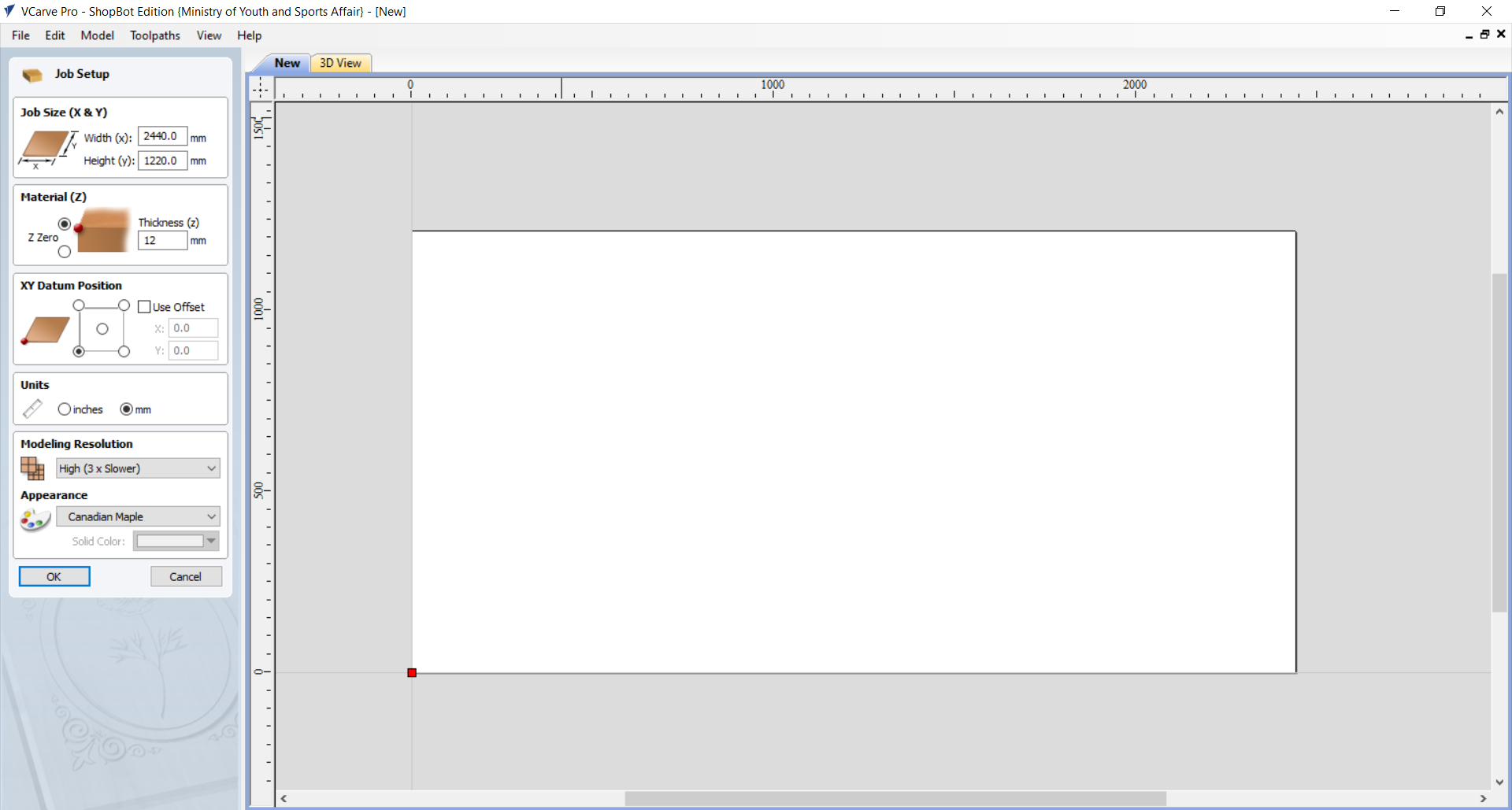
2- Set the sheets sizes, material and other settings. As follows:
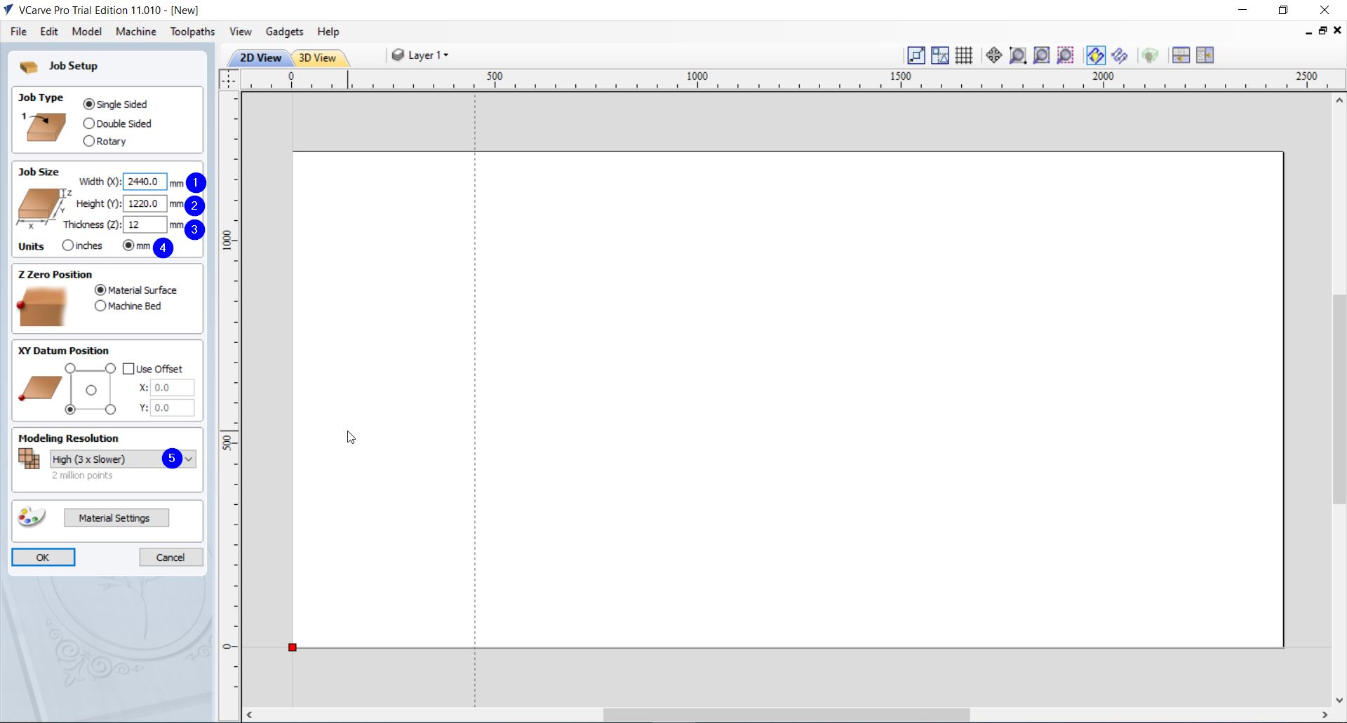
Important Note: Make sure to select the right measurements units.
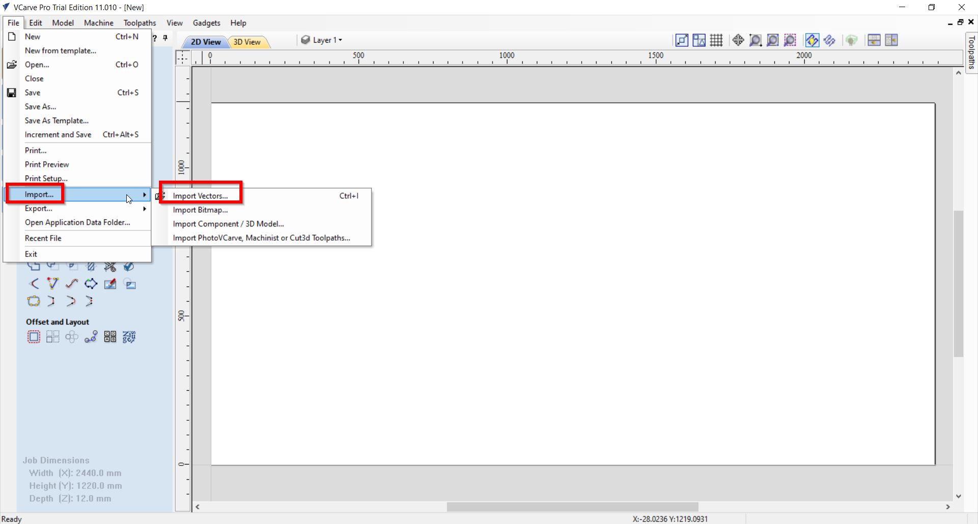
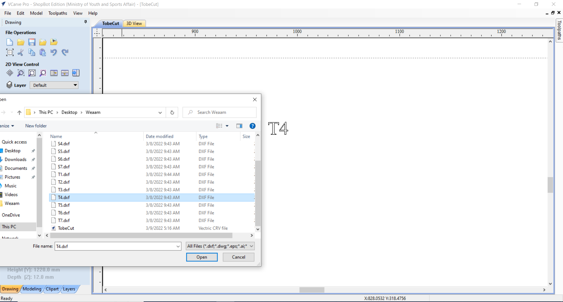
3- If you want to Import a design from file > Import > Imports Vectors:
Note: You might not find the design folder as follows:
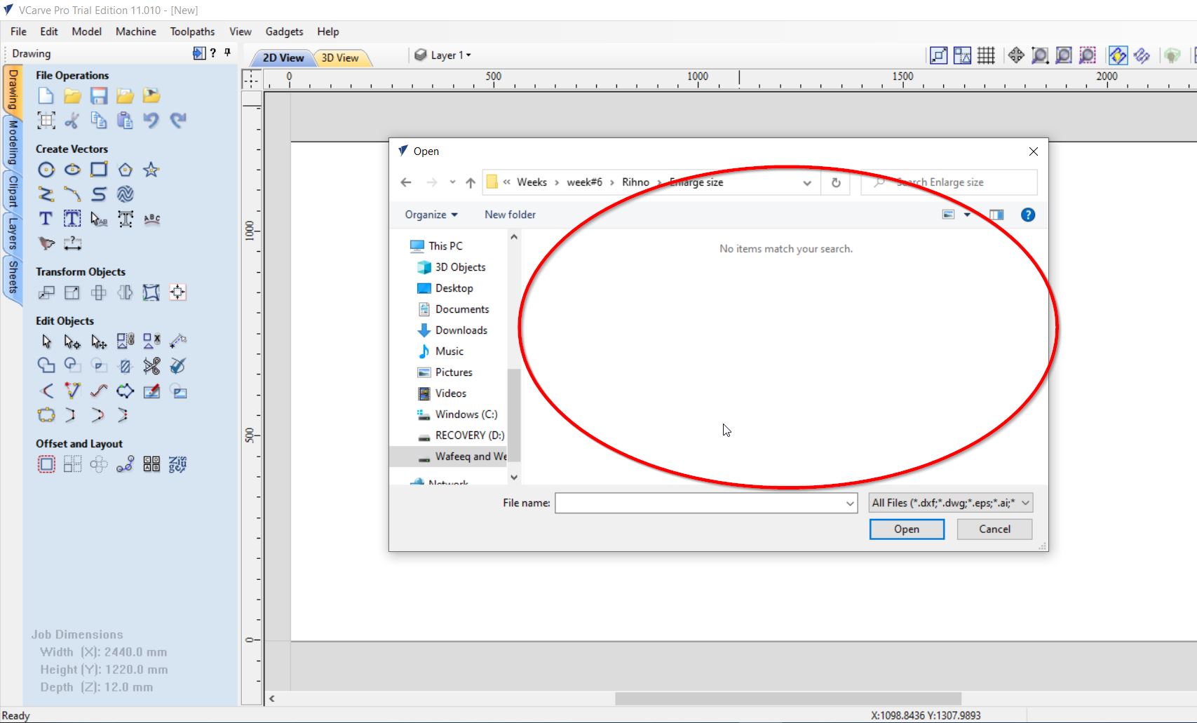
Thus, make sure to save a readable format of the design file. For Instance, use “.dxf”.
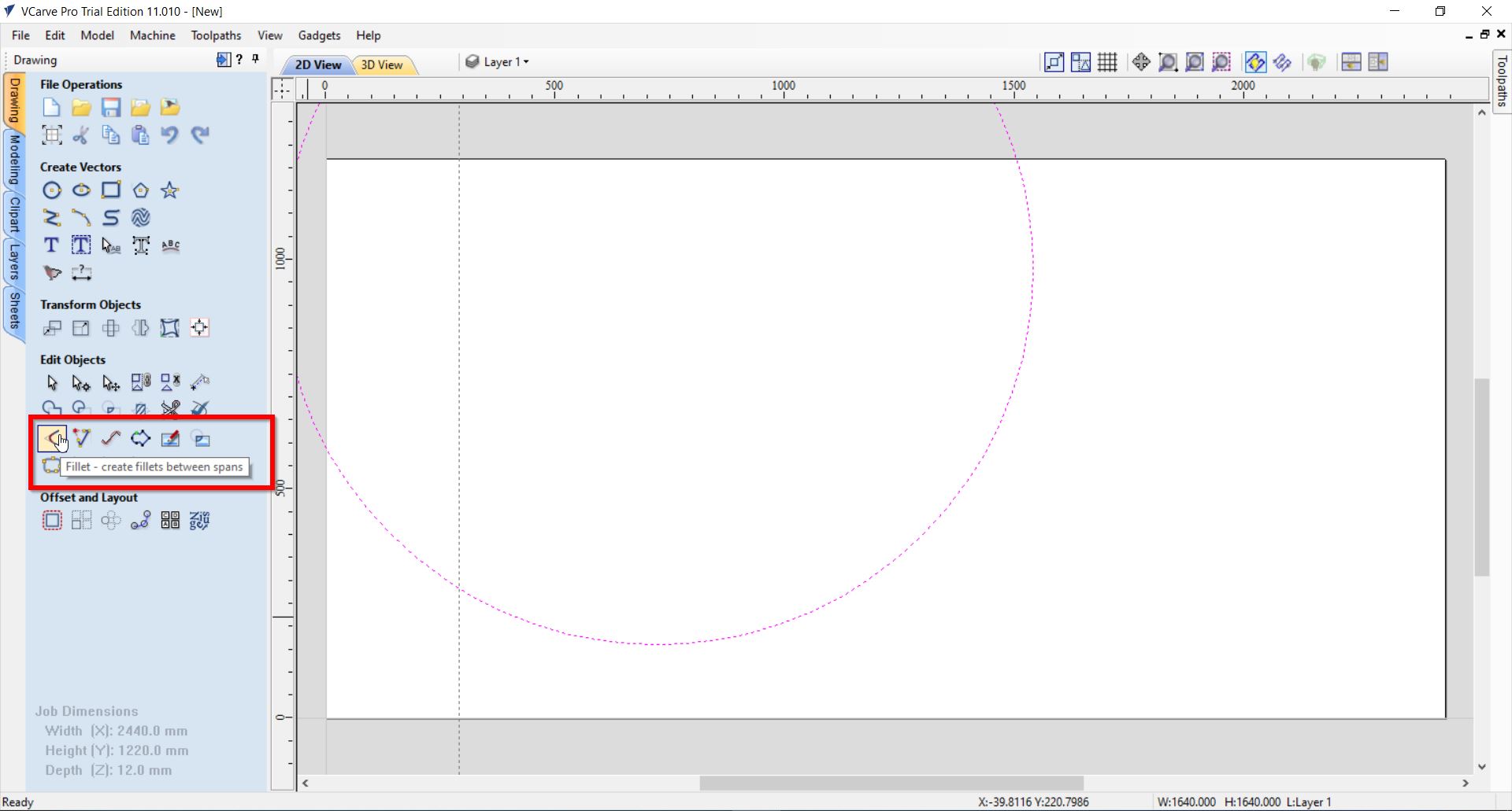
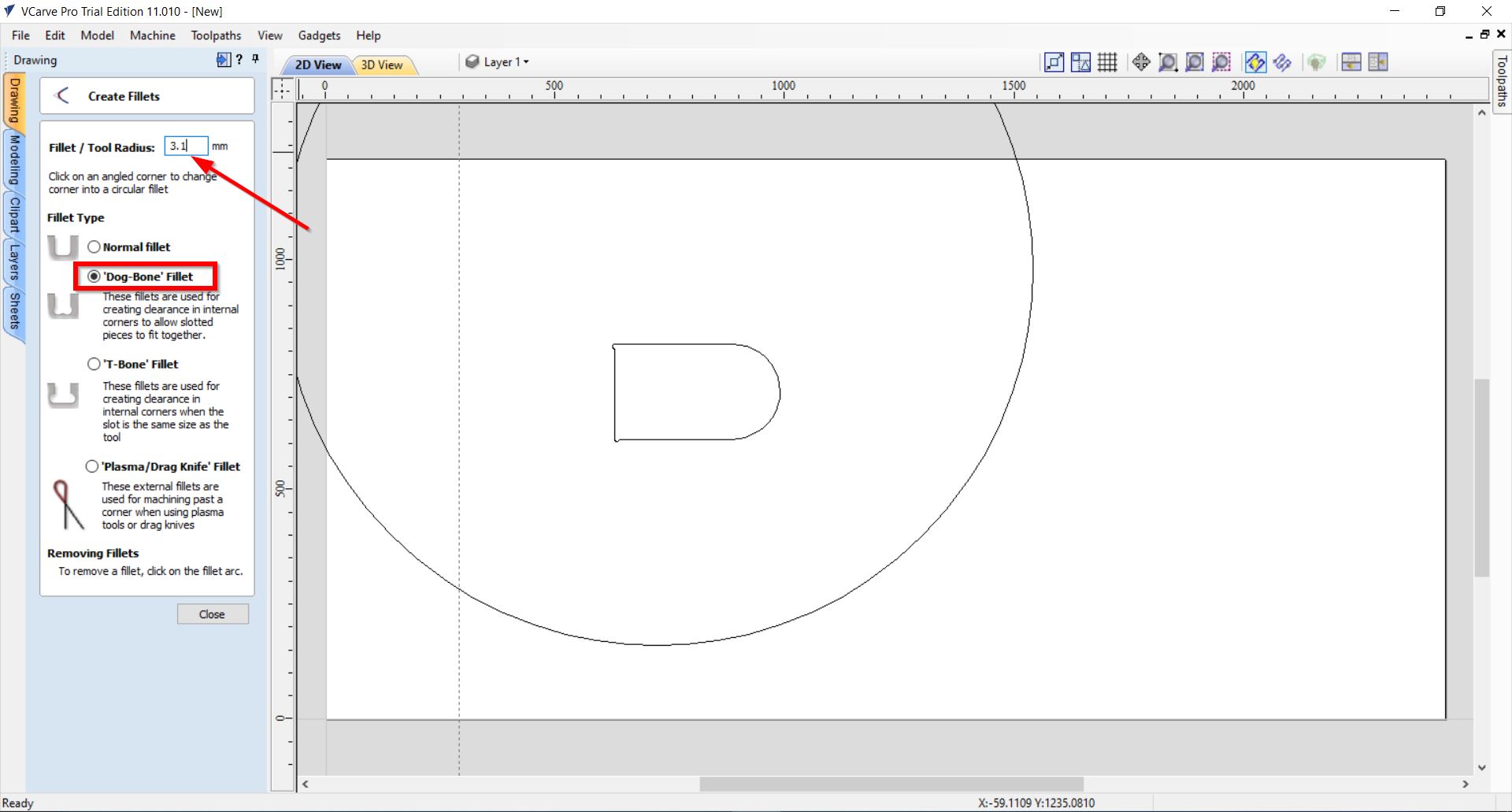
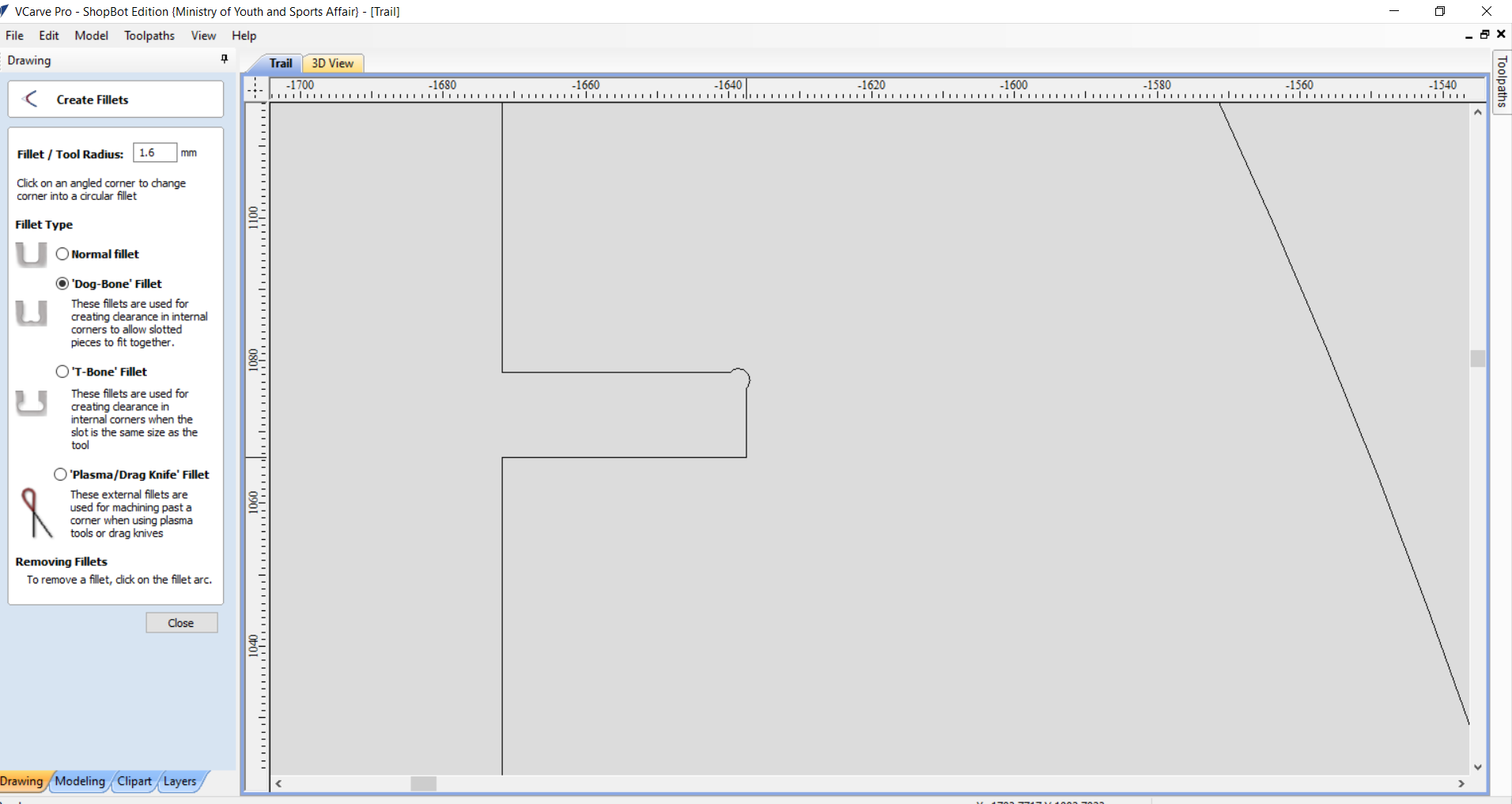
4- You can then create fillets between the joints. From the “Fillets” tool:
Select the “Dog-Bone Fillets” and set the fillets radius as 3.1. Then, click on the design’s joints :
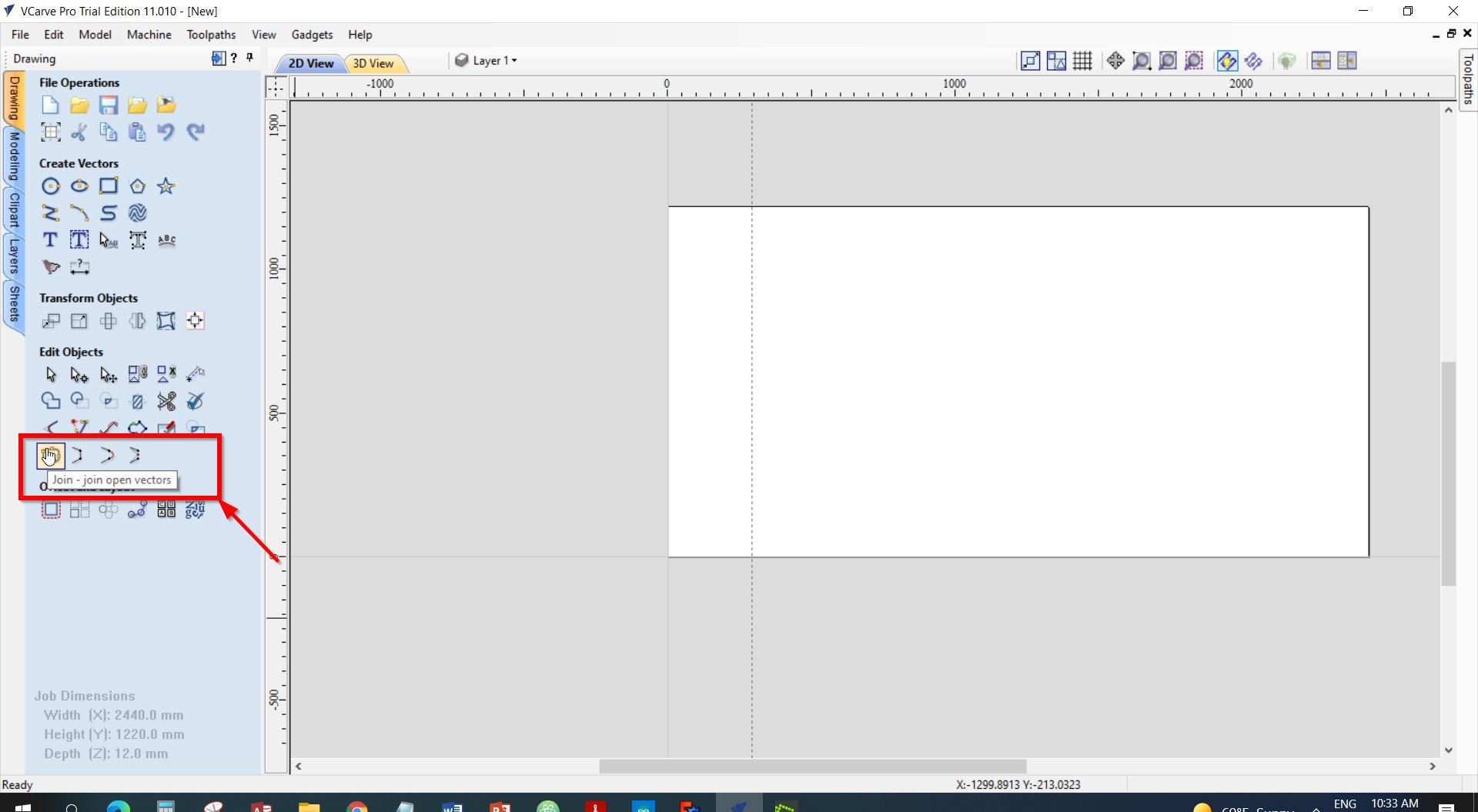
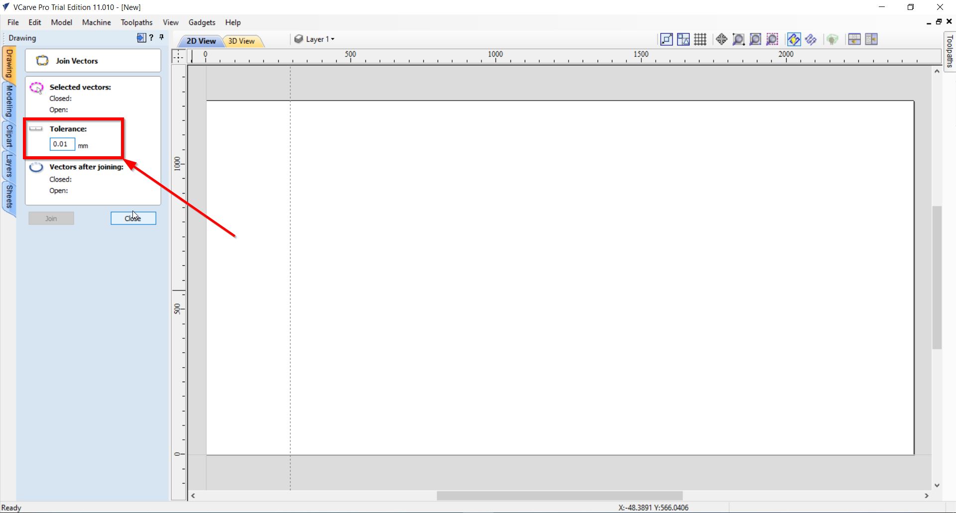
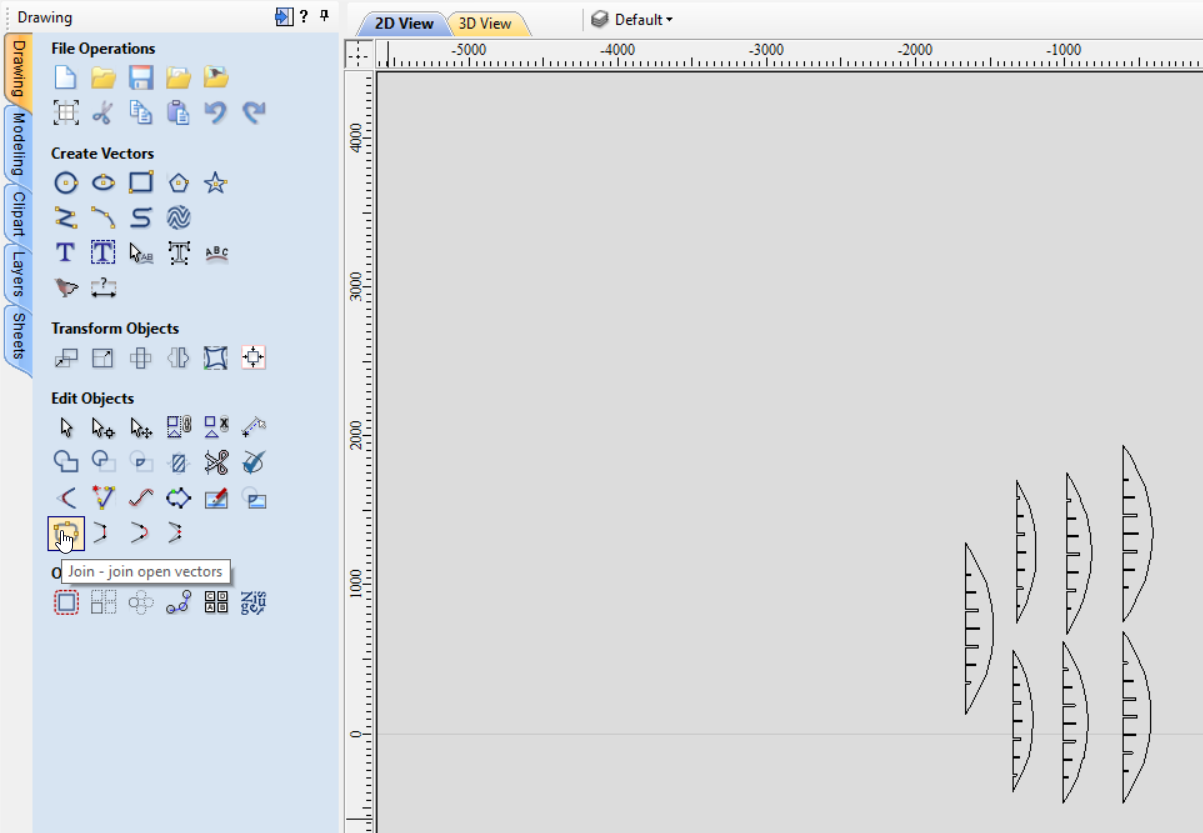
5- It is important to make sure that all the joints of the design are joined. Hence, you may select the following “Join” tool:
Note: To make sure about the accuracy and the joint remains the same measurements; set the tolerance as ((0.1)). As it is shown below:
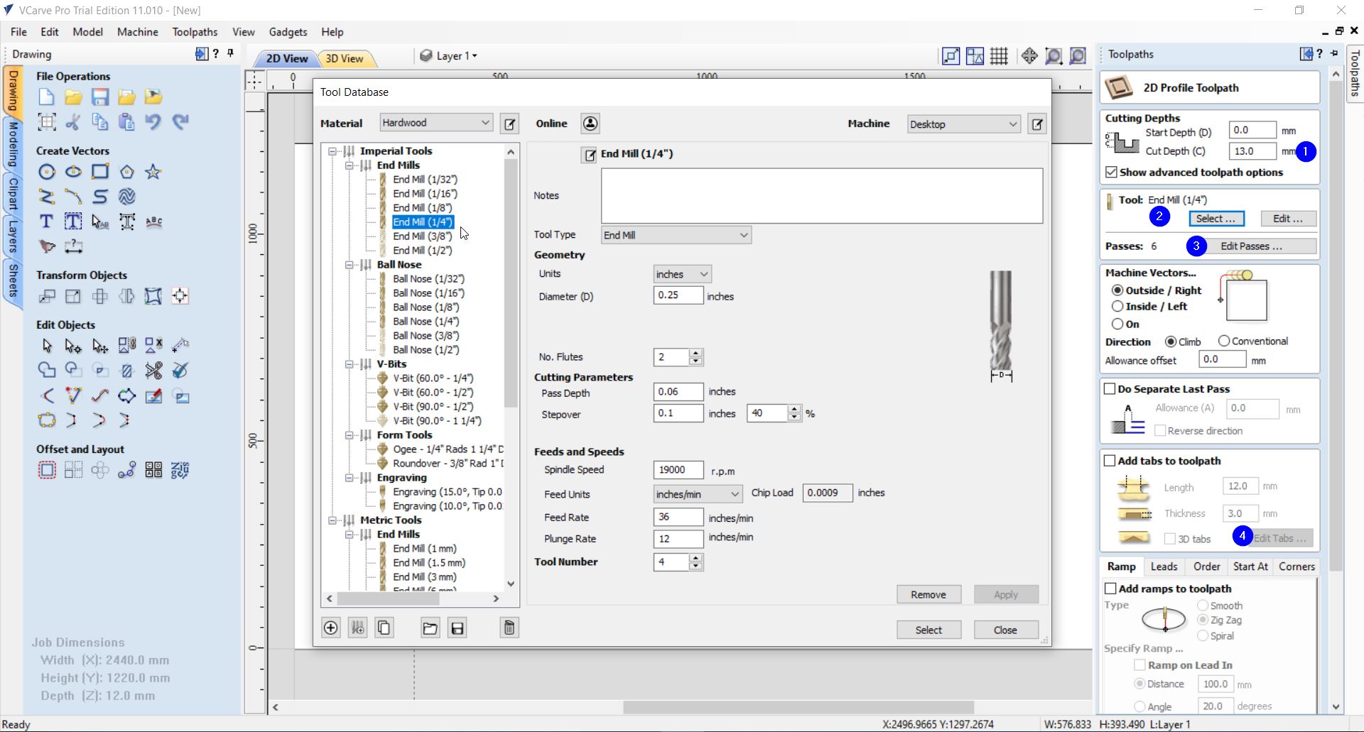
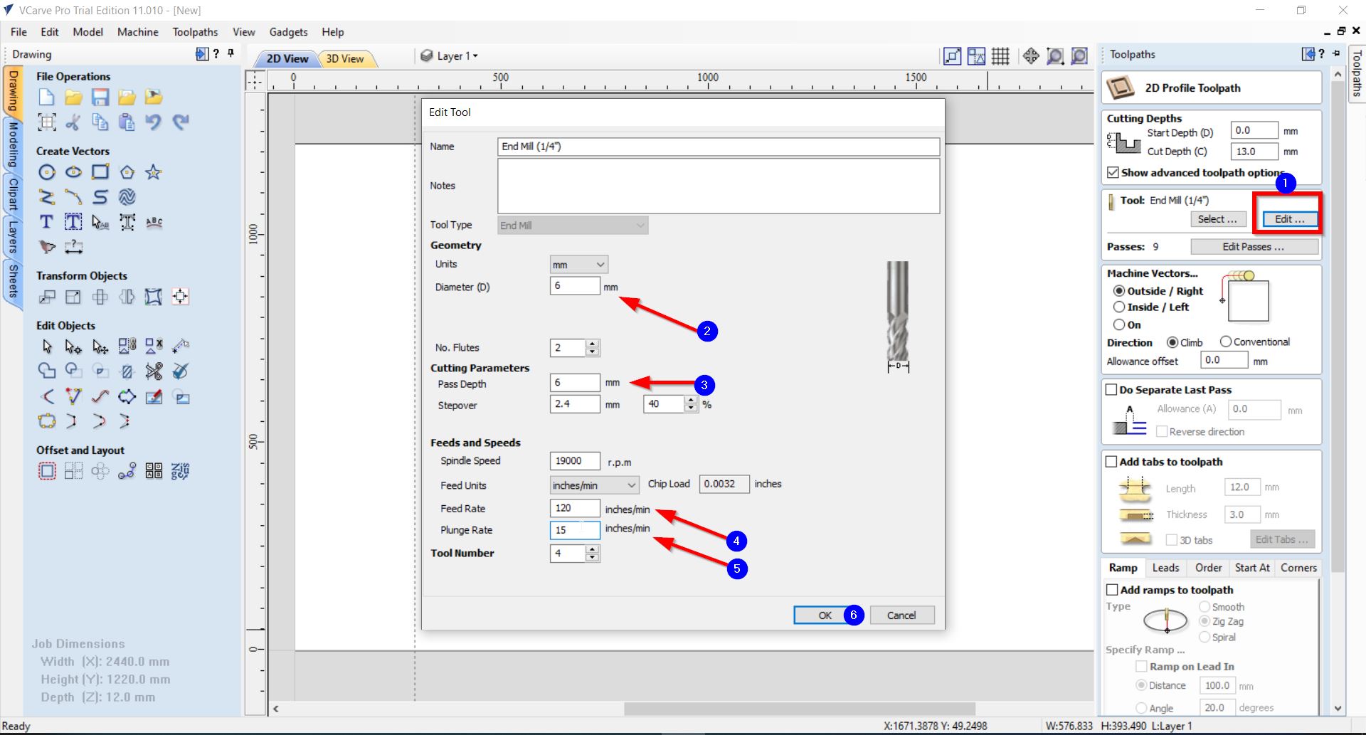
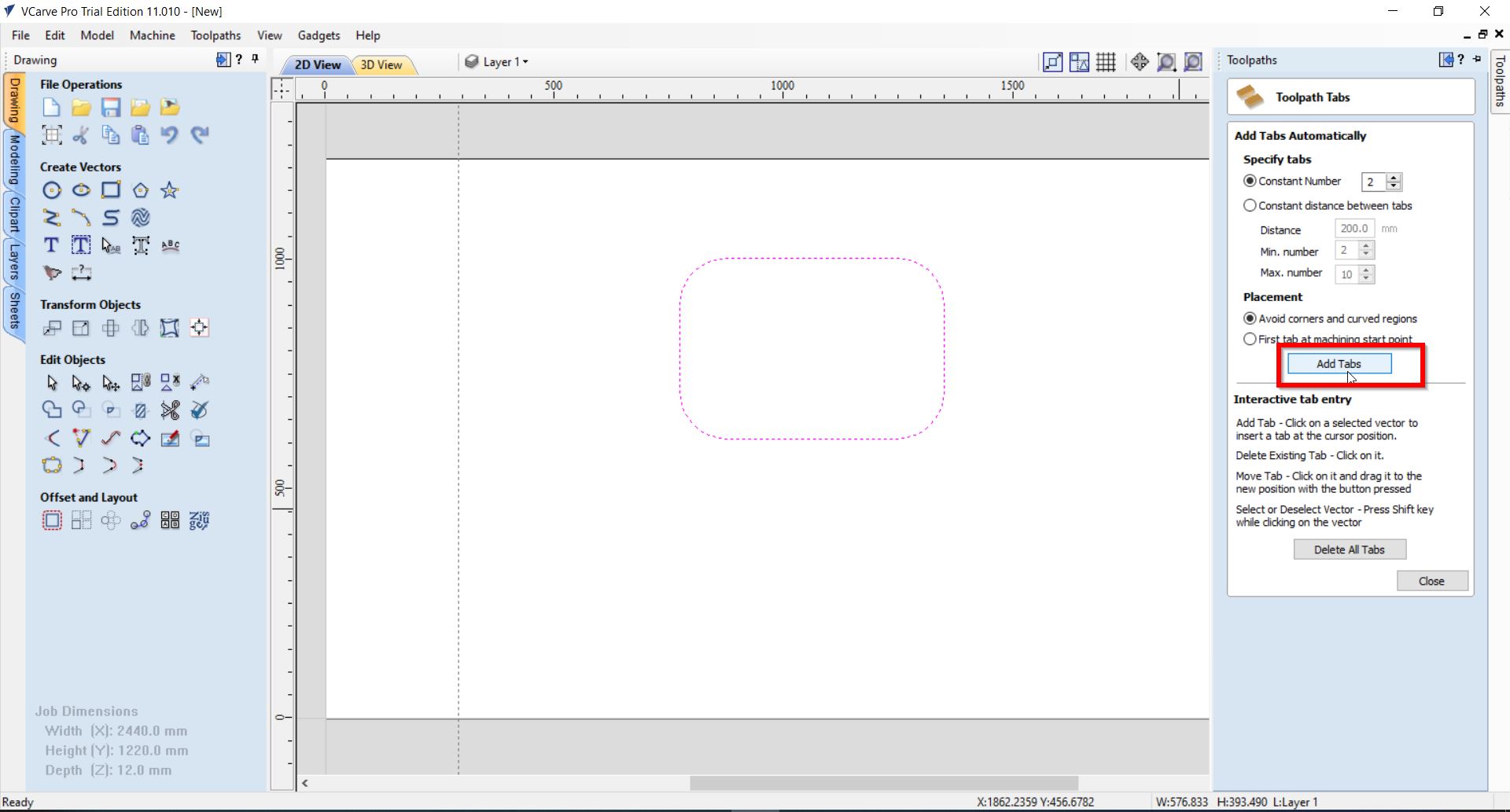
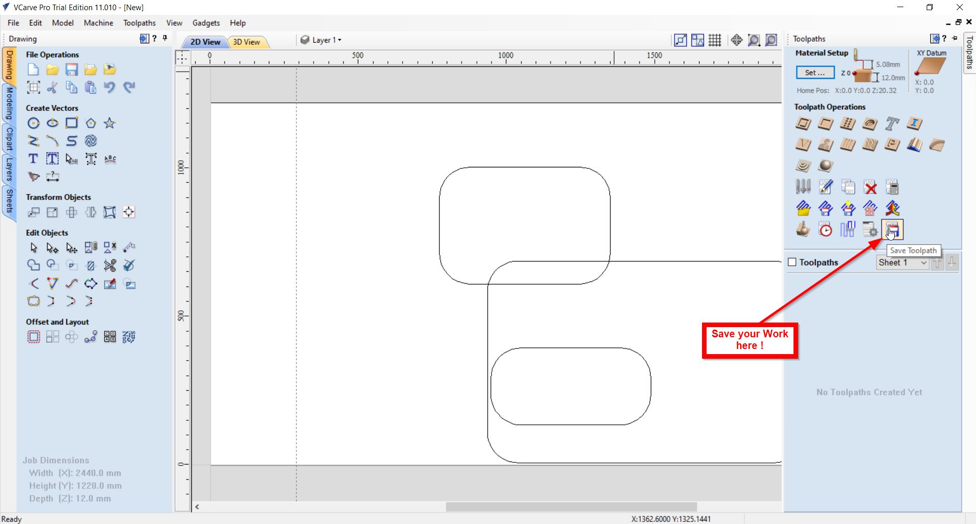
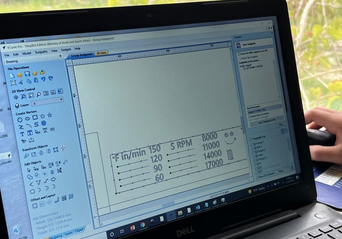
6- You may go further to edit and customize the toolpath by clicking on the “Toolpath” menu found in the right-hand side of the page. Below you will find an example of our testing trial:
7- Finally, you can save your toolpath by clicking on the following button:
To further learn about how to use the VCarve software, you may refer to the YouTube video below:
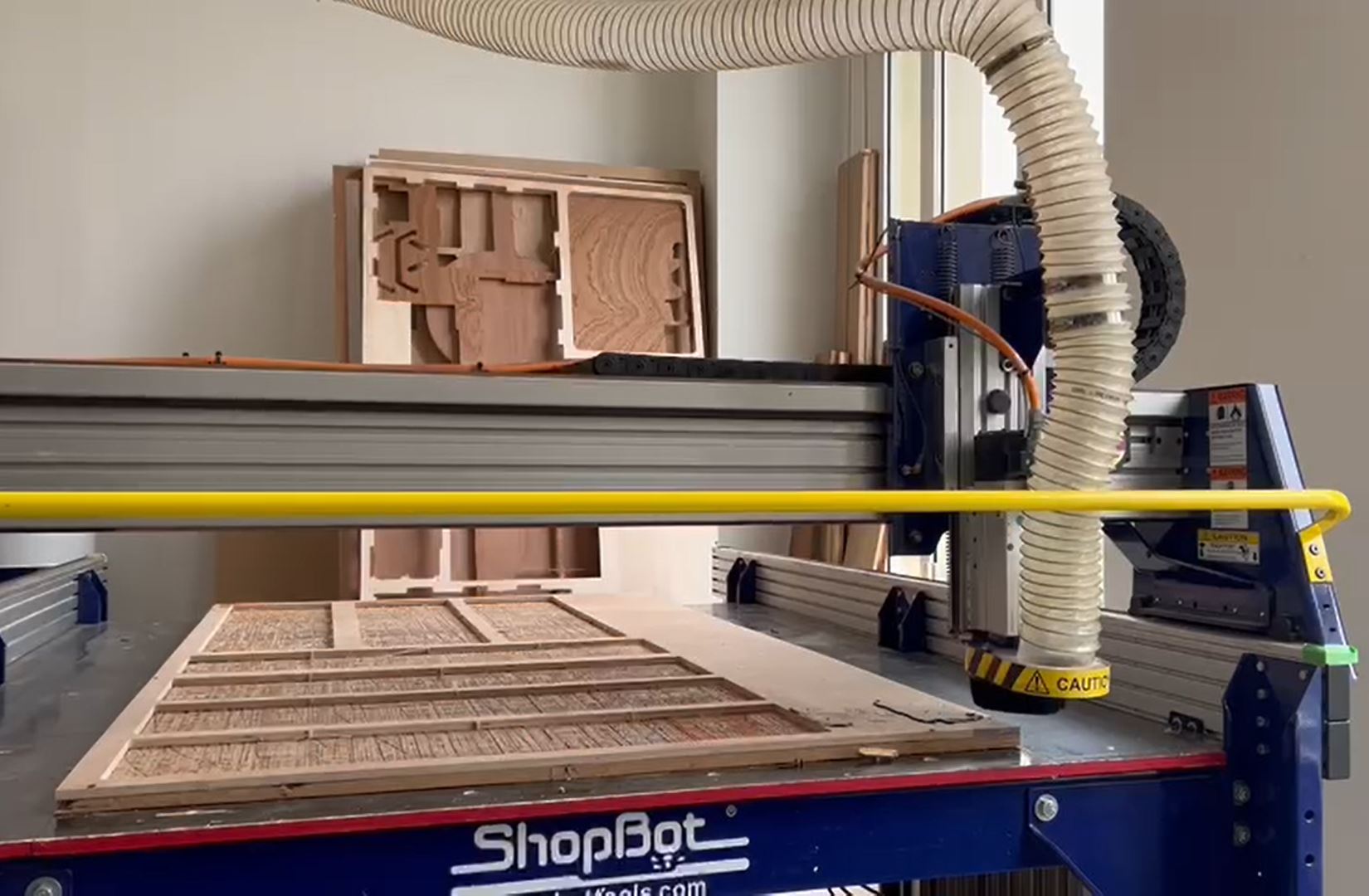
Testing the machine
To further develop our knowledge on the runout, alignment, speeds, fillets & feeds machine. The instructor took us through the following procedure:
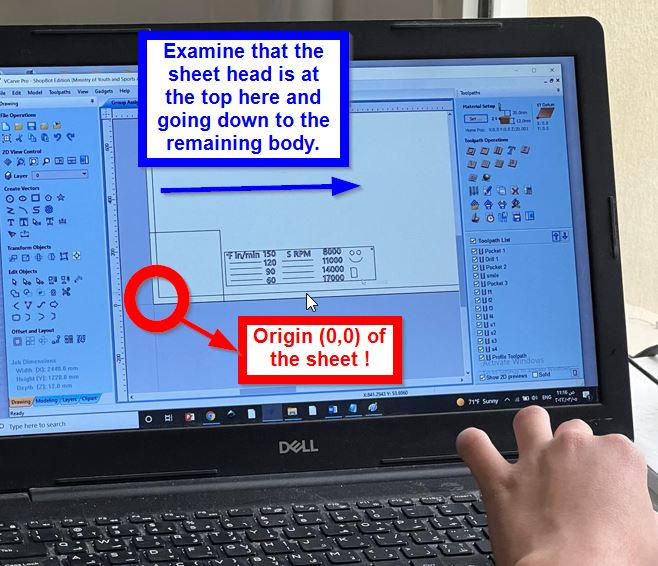
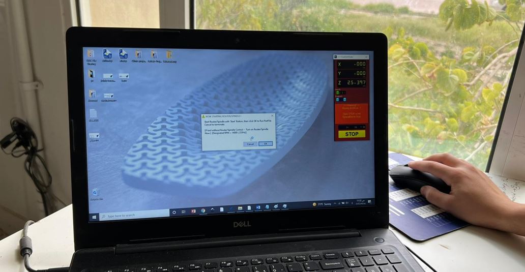
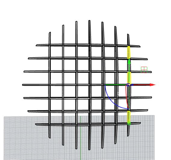
- Using the VCarve software, we have placed the design and edit it using the toolpath:
Please note: To place the design in the right place on the sheet; you need to view the sheet this way:
- Upload the design to the CNC Machine:
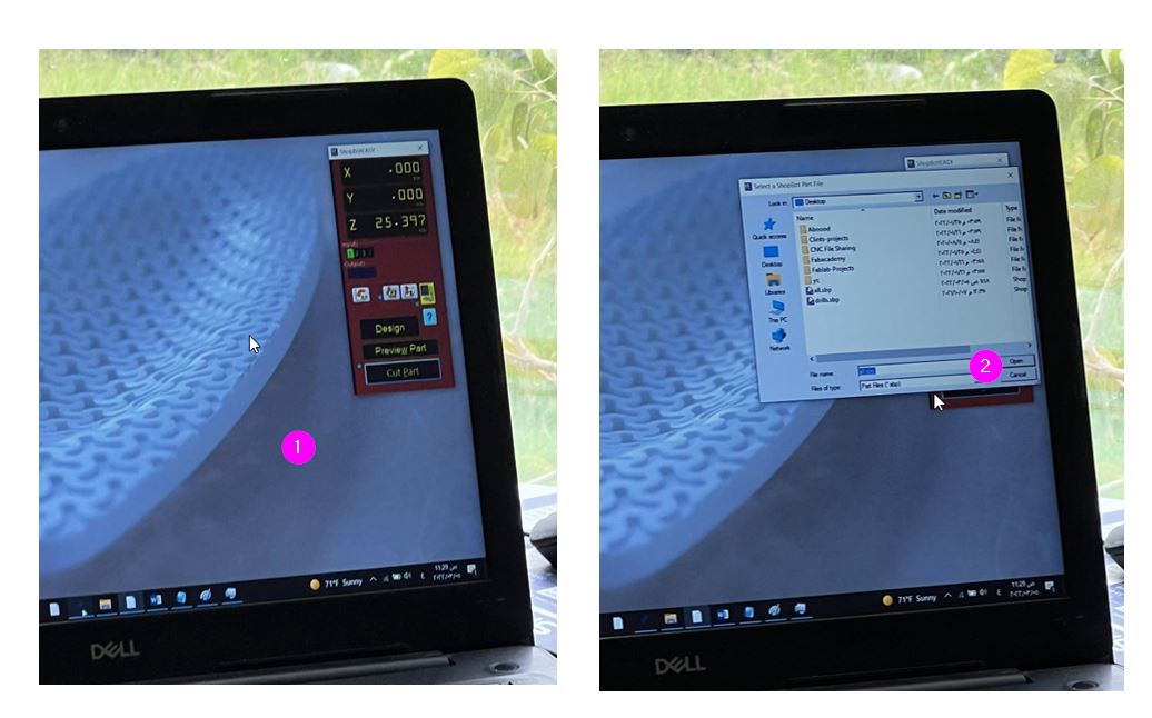
- Select the position & origin of the bed:
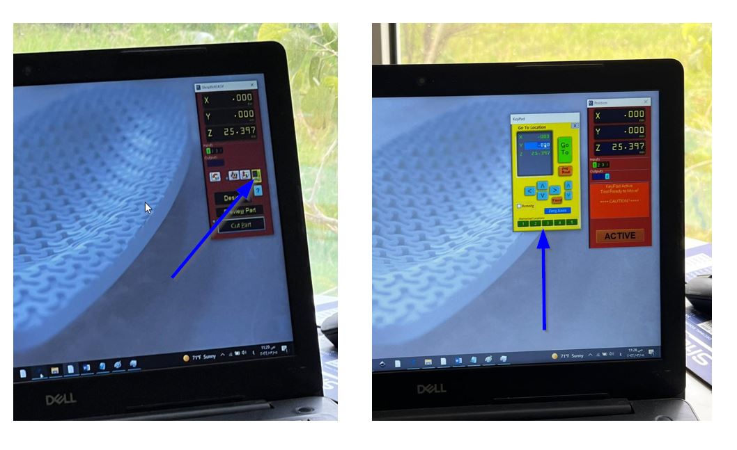
Before starting the cutting process you should do the following settlements:
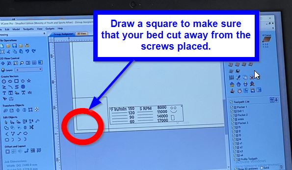
- Make sure to hold the wooden sheet in one place. For us we have used screws; as follows :
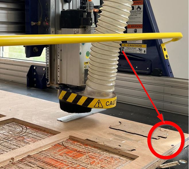
- However, the CNC machine’s bed might break when it goes over the screws. Hence, to prevent this try to leave 3 cm margin form all edges; and paste your designs apart from the edges. As follows:
- Use the metal plate to make sure that the bed at the right place.
- Then, you can press cut to start the “cut part” button, press okay, and the green start button:
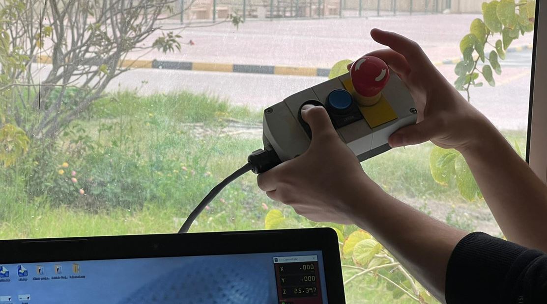
Note: if you clicked any computer’s button (after pressing the start button), the cutting will be paused.
- The cutting process have beem started:
- Final Result:
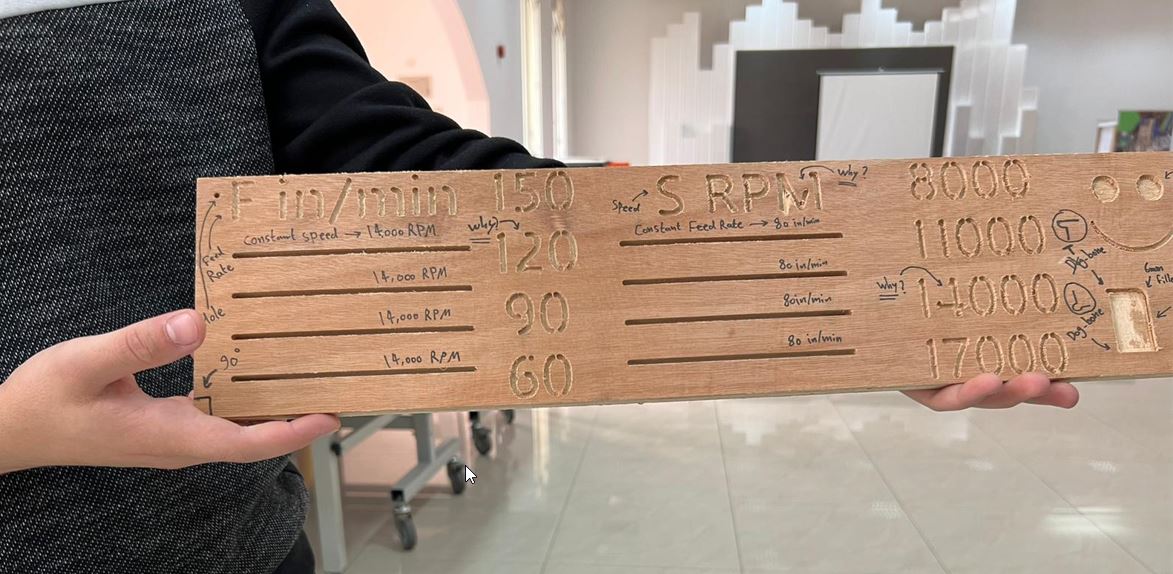
After cutting the design, the instructor have discussed with us:
-
The effect of speed and RPM on cutting the designs.
-
The reason behind the un-cut parts (for instance, for number 4 it did not cut the parts where the object hole become very small) because the bed can’t pass through.
-
Types on fillets.
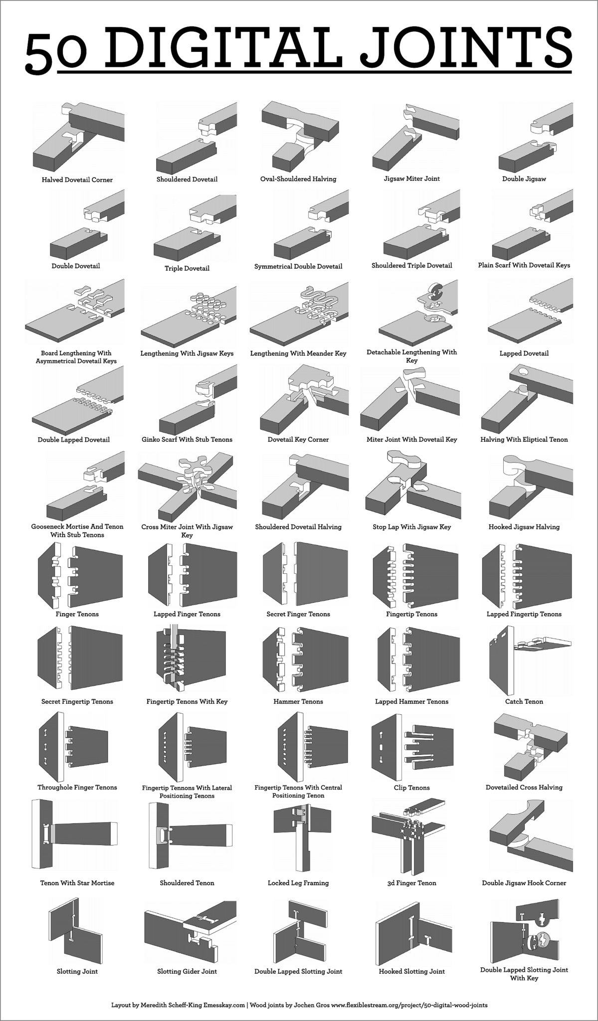
Design’s Joints types
The instructor then introduced us to the different types of joint and the purpose of every joint. Here is a small view of the instructor explanation:
To further about the joint types, here is a good reference:
Individual Assignment
Problem Description
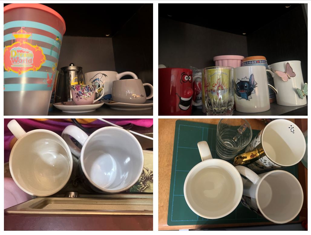
Throughout the past years I have participated in various programs, travelled to different countries, build new relationships, and create memorable moments. I have always tried to retain my beloved memories and experiences through a cup ! For instance, after we finished the robotics competition in Dubai I have distributed a unique cups for Team Bahrain. So, whenever I use any cup I re-fresh my memories. As a result, I end up with this mess all around my room:
To overcome this issue, I have bought shelves however they are not functional. Because, once I try to get a cup the other falls. Thus, I thought of creating a customize cup shelves to display my cups; similar to these ideas:
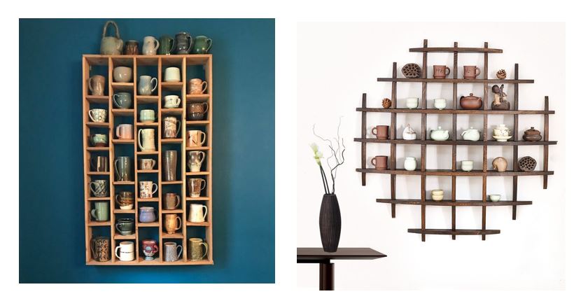
I loved the sphere-based shelves for two reasons. Firstly, it looks unique and different than the standard shelves. Secondly, it gives insights of the Earth. Which refers that every cup may be manufactured or bought from different country. Moreover, each country have different history/story similarly each cup have a different story behind it !
Designing Phase
Trial 1
For the first trial, I tried to design the cup shelves using “FreeCAD” Software as follows:
- Select file > new > Part Design > New body > XY_Plane

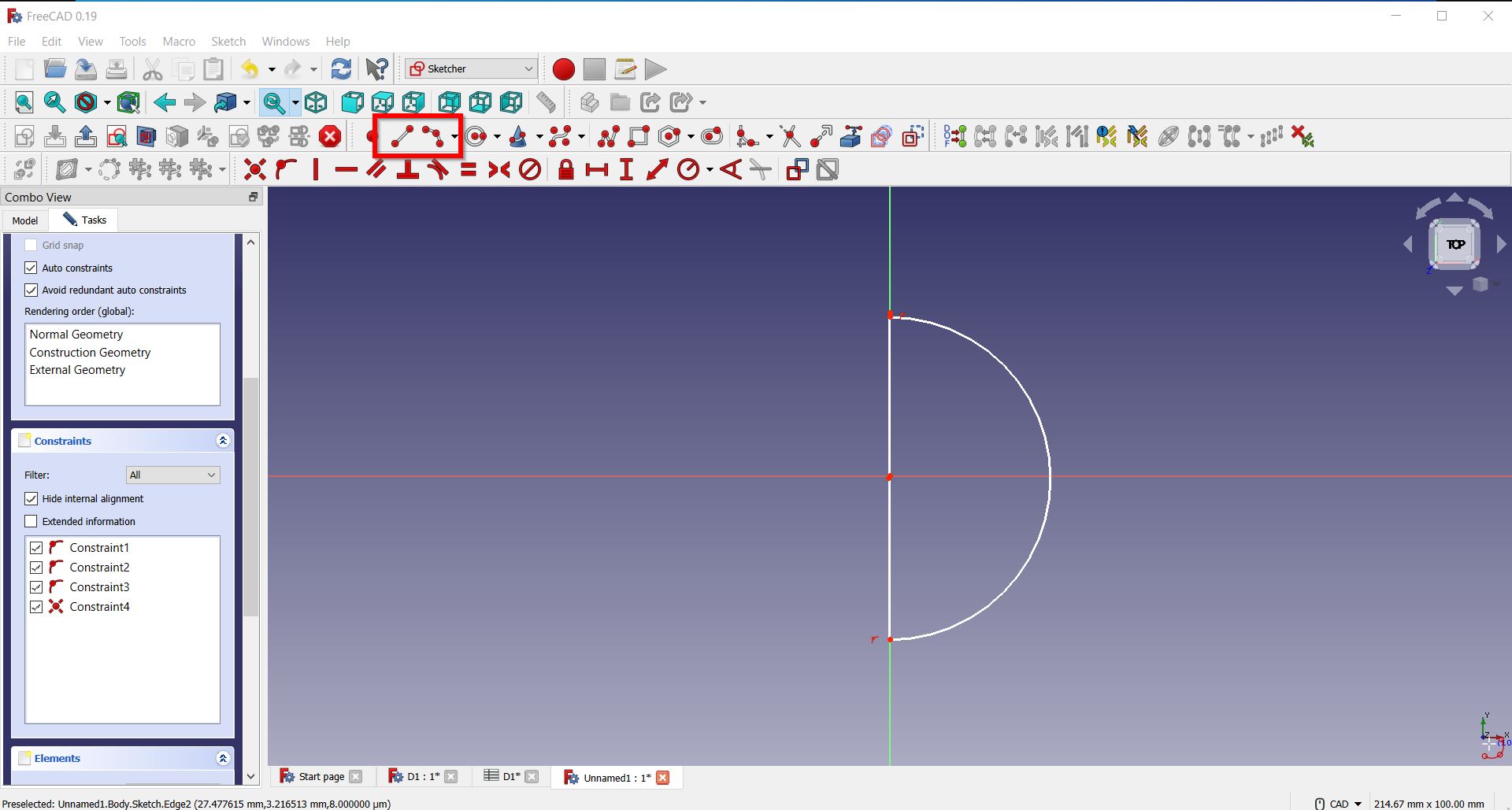
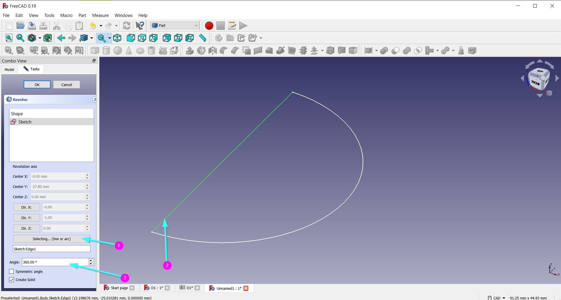
- Using the lines and curves, I drew the following shape:
- Using the “extrude” part, I did the following:
- Then, I drew lines to extrude them:
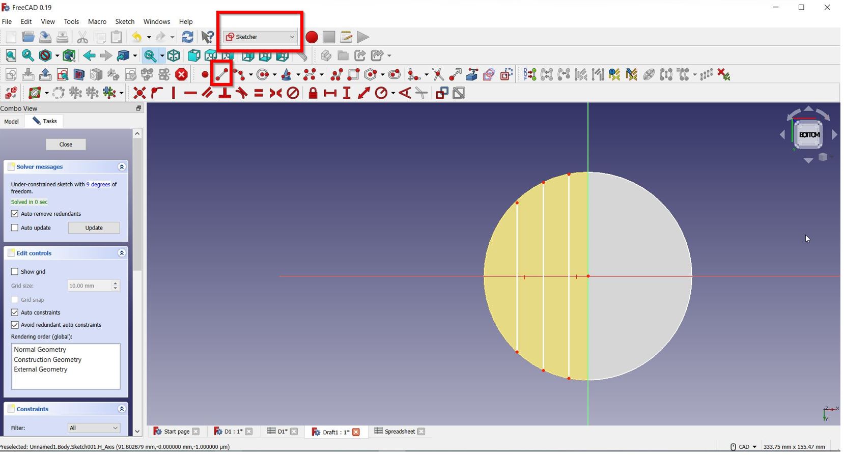
- Afterwards, I tried to extrude the line as shown here:
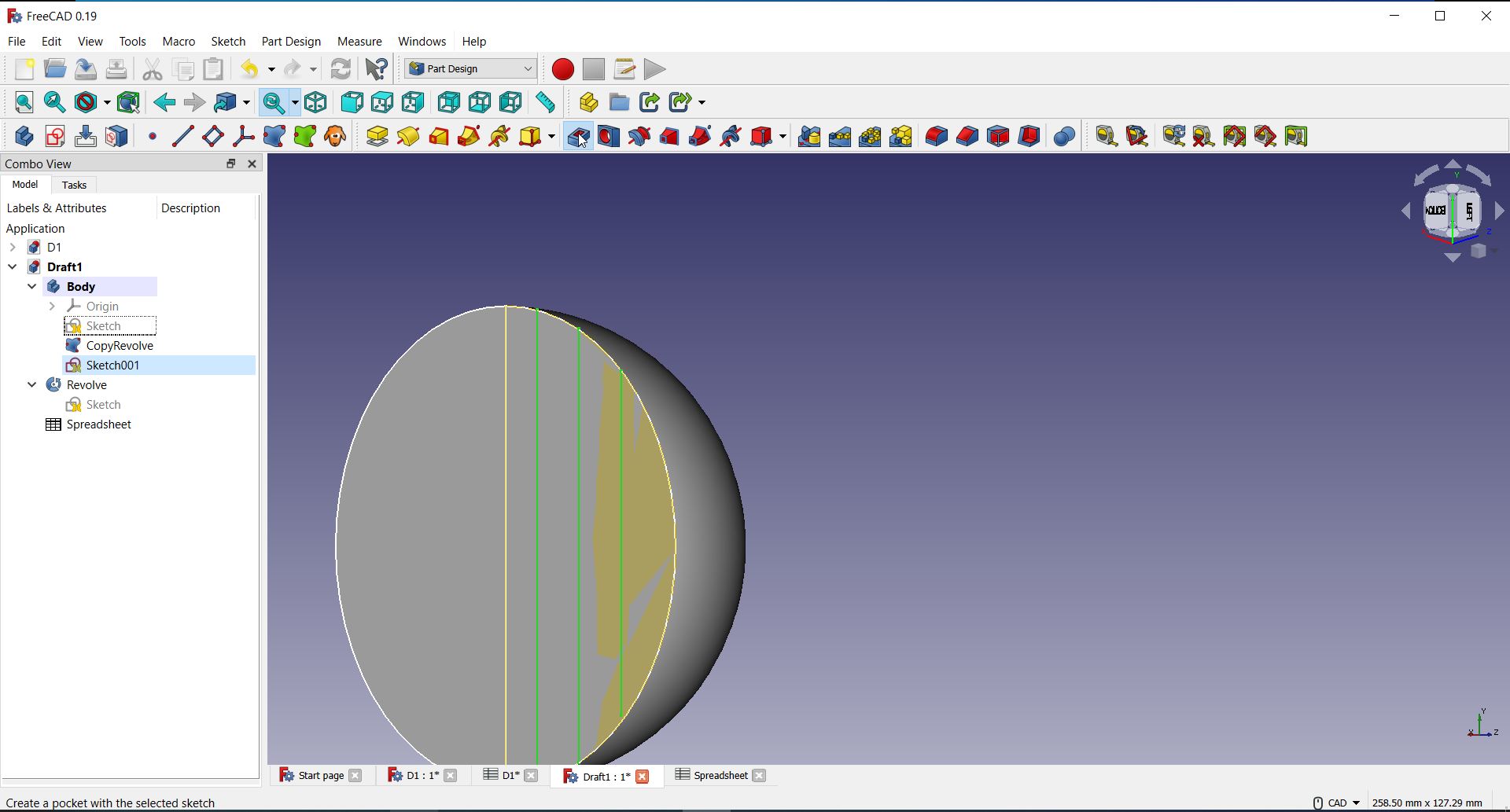
However, the extrusion have not succeed for many reasons. There was errors that appear to me; I tried to solve them but the software was lagging. In addtion, I do not have high skills with using freecad software.
Trial 2
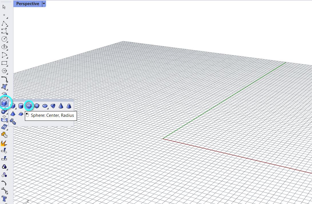
But I did not give up ! I went to download the Rhino7 software and accessed its free license through this link .
Here you will find dome guidelines that I have noted about the Rhino7 software:
1- There is four environment: Top, Perspective, front, Right.
2- You can view each environment by double click to go back to the full view by double clicking on them.
3- You can rotate your view by:
- Clicking your right mouse.
- To pan around the screen = press shift & right mouse.
- Zoom in-out = use your mouse wheel.
4- To change the background color you can press on Tools > Options > Appearance > Colors > Background
5- You can add the same shape you paste previously by also right Clicking on it.
6- Nerves = gives smooth shapes. Whereas, Meshes = gives shapes with vertices and freeform feeling.
7- To do parametric design in Rhino you may first type “Grasshopper” in the command field.
I have successfully accomplished the design through the following steps:
- Firstly, I have dropped a sphere shape :
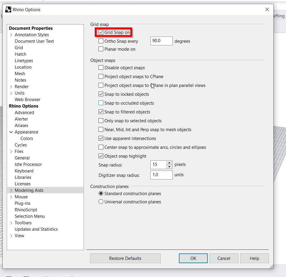
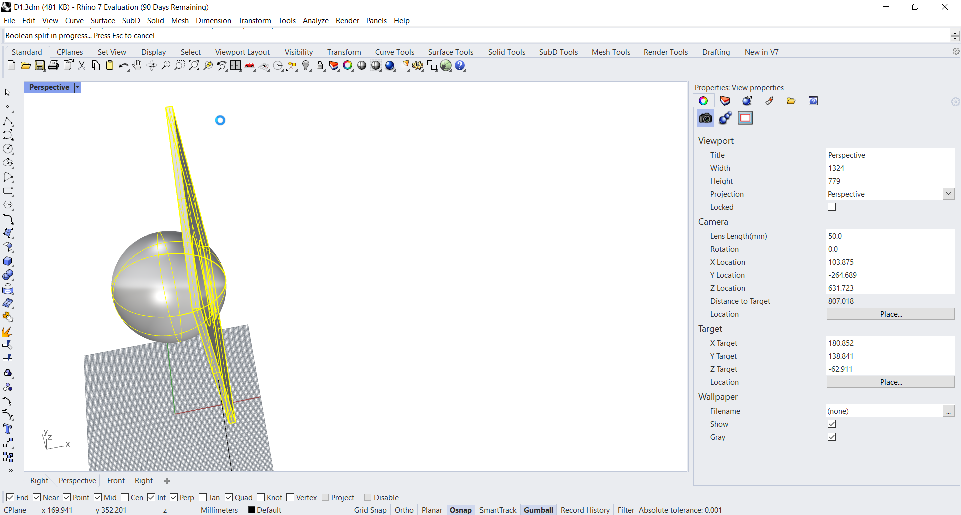
- I have turned on the “Grid Snap on” from the setting (preferences option):
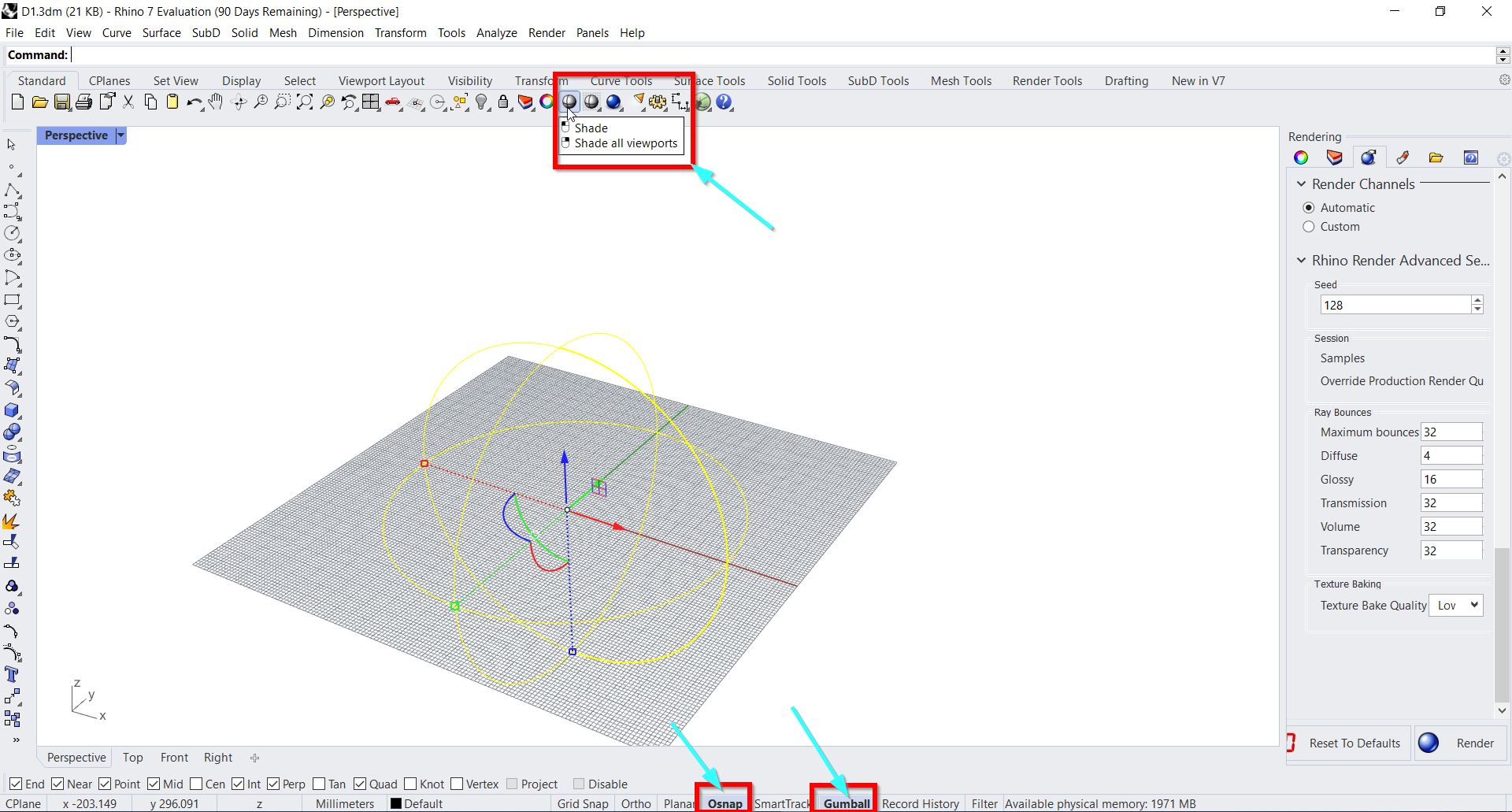
- Then, I turned on “osnap” & “Gumball”; and select all shade viewports:
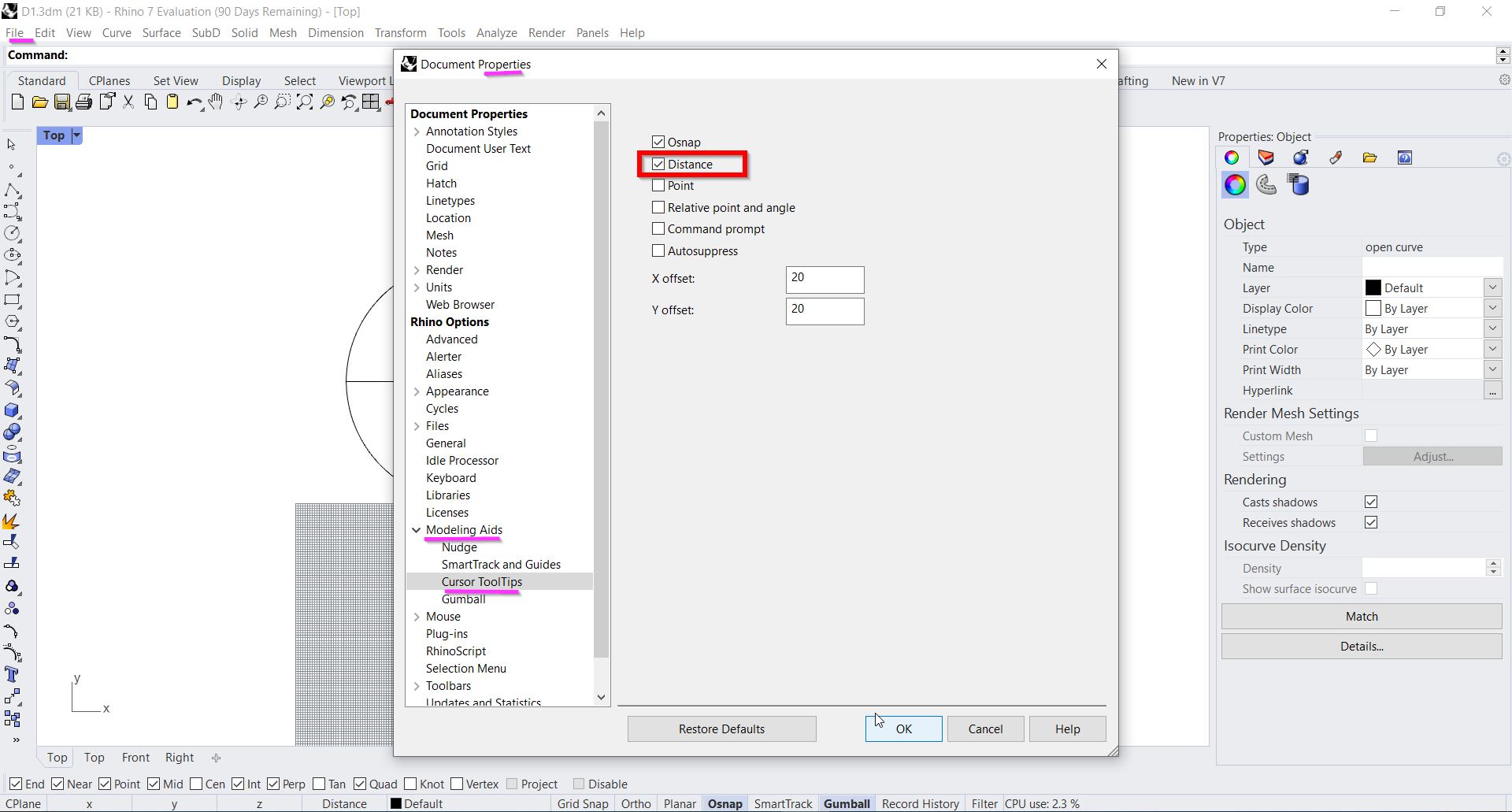
- The distance cursor tooltips have been turned; through File > Modelling Aids > Cursor Tooltips > Distance:
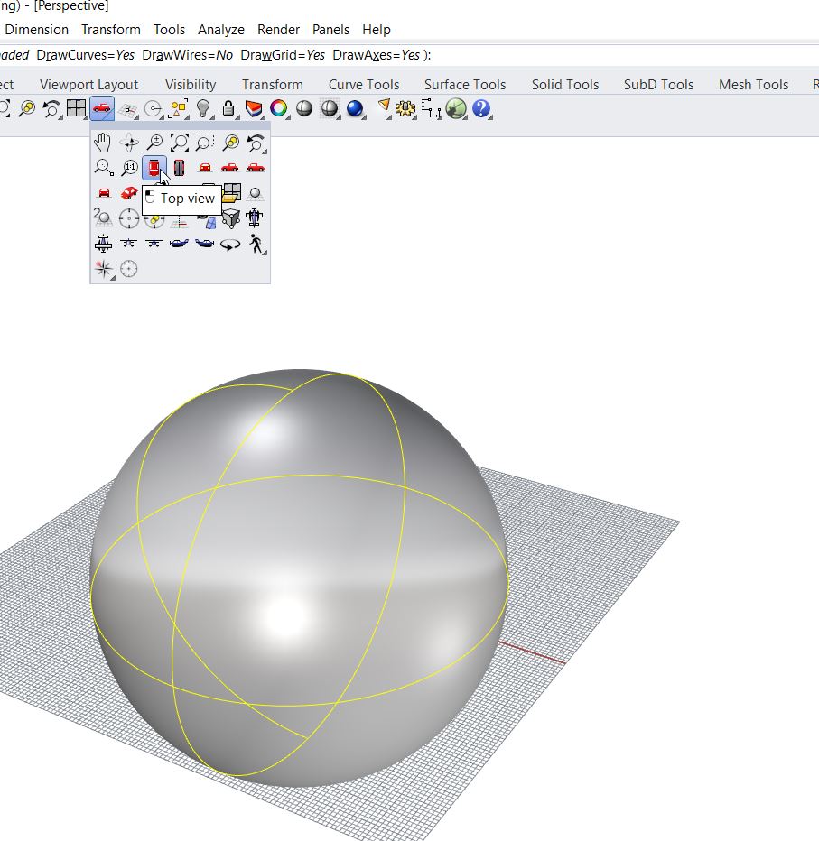
- Top view was selected:
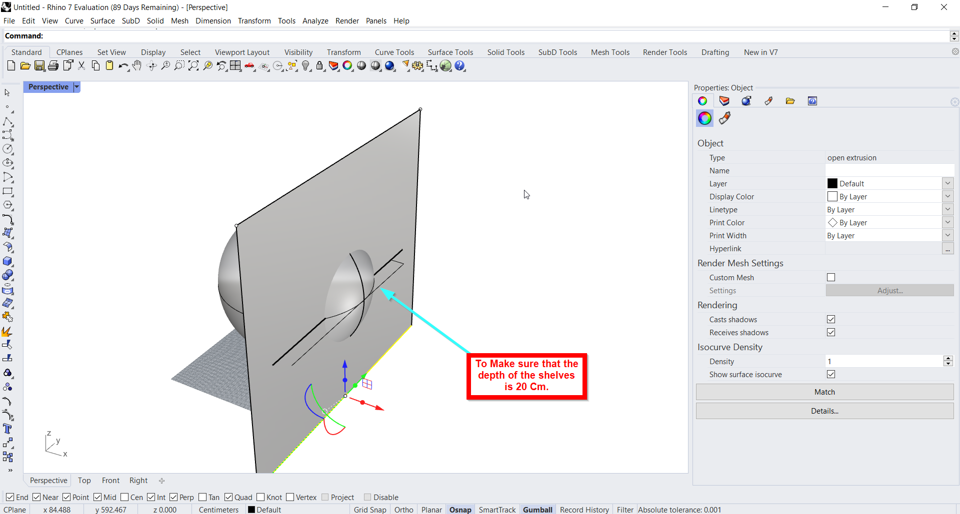
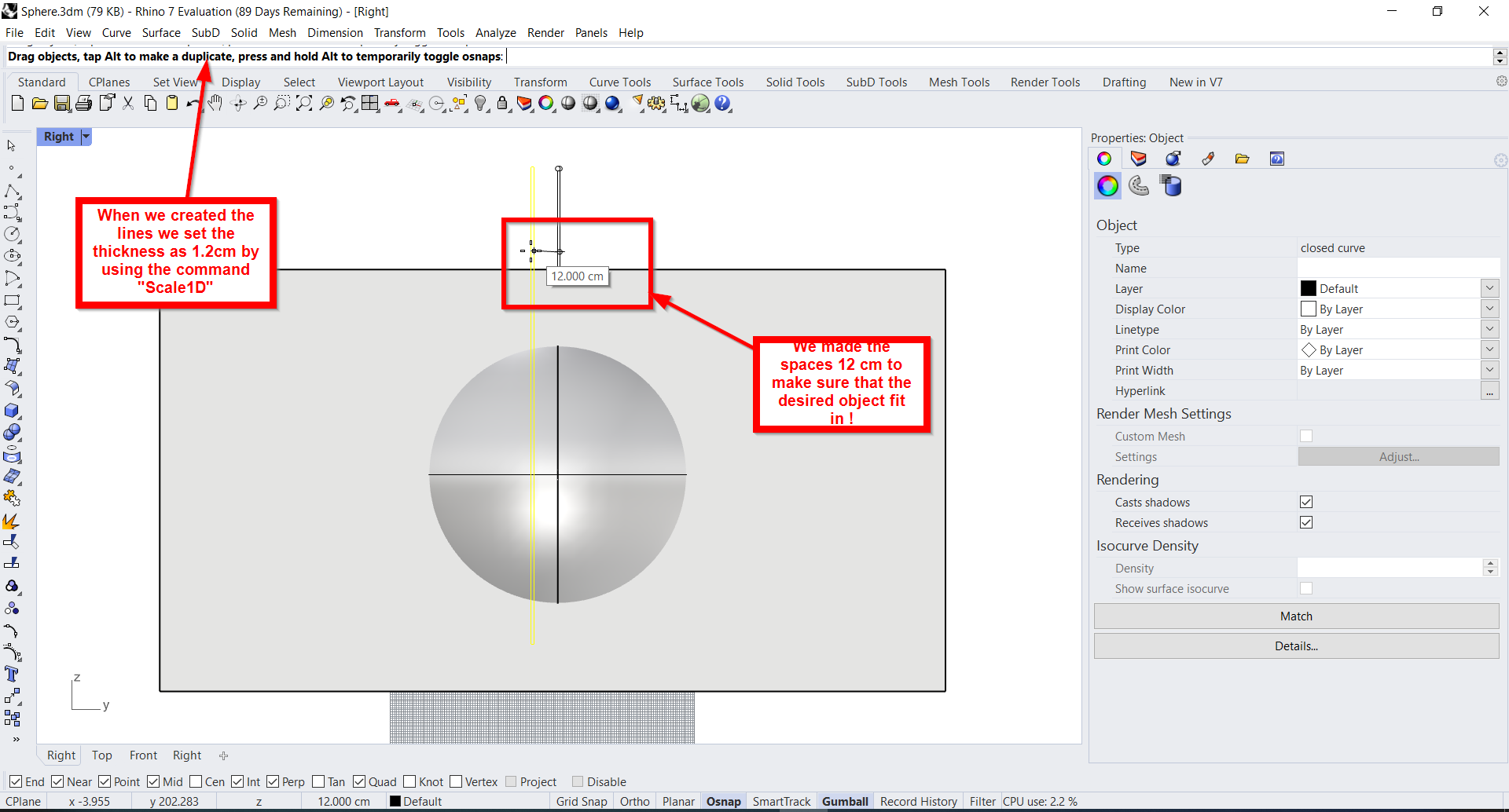
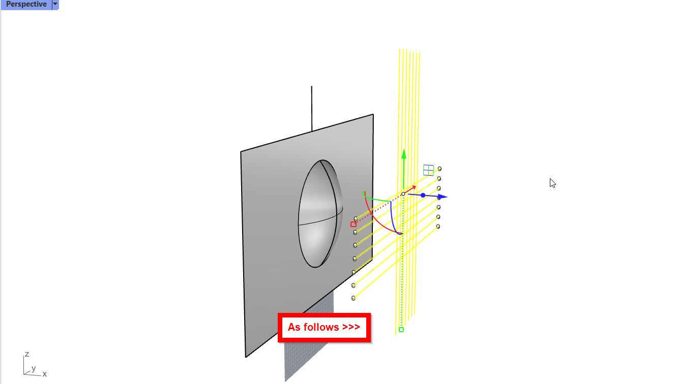
- To select the depth of the shelves I have drawn a rectangle and lines as follows:
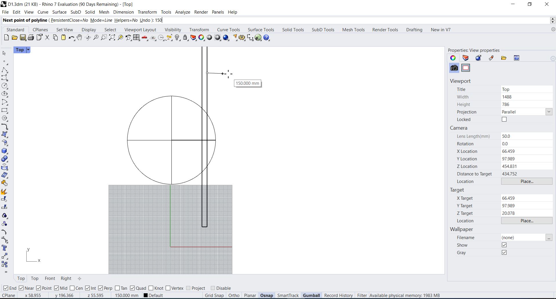
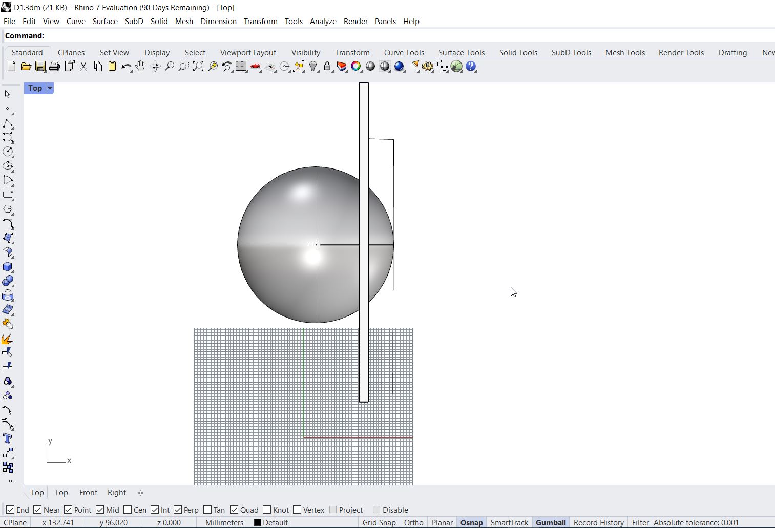
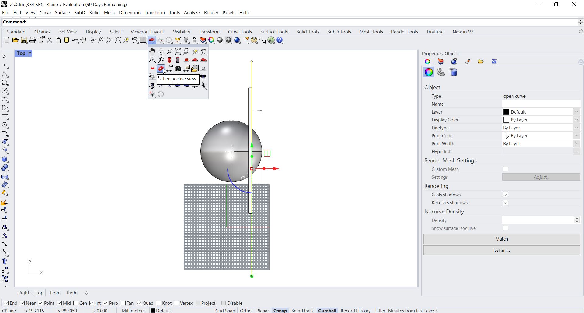
- A line was drawn and the preview was changed to “Perspective view”:
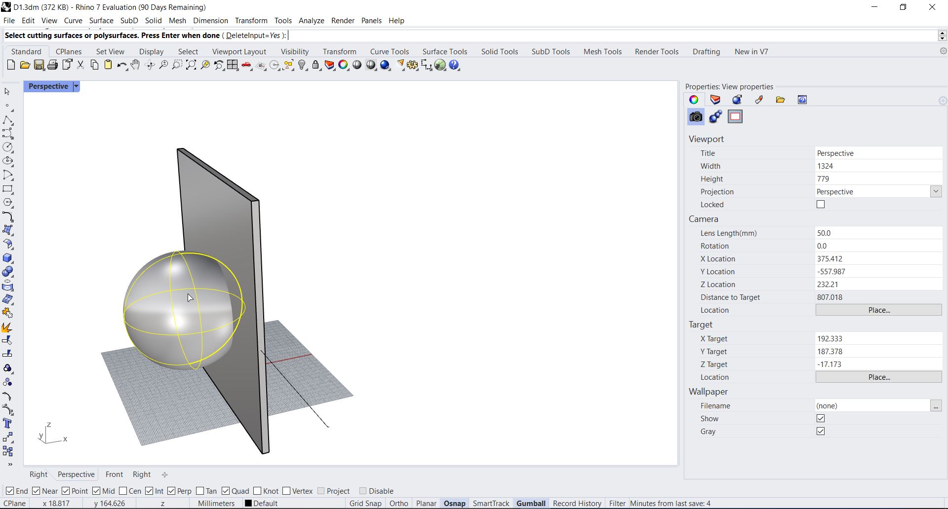
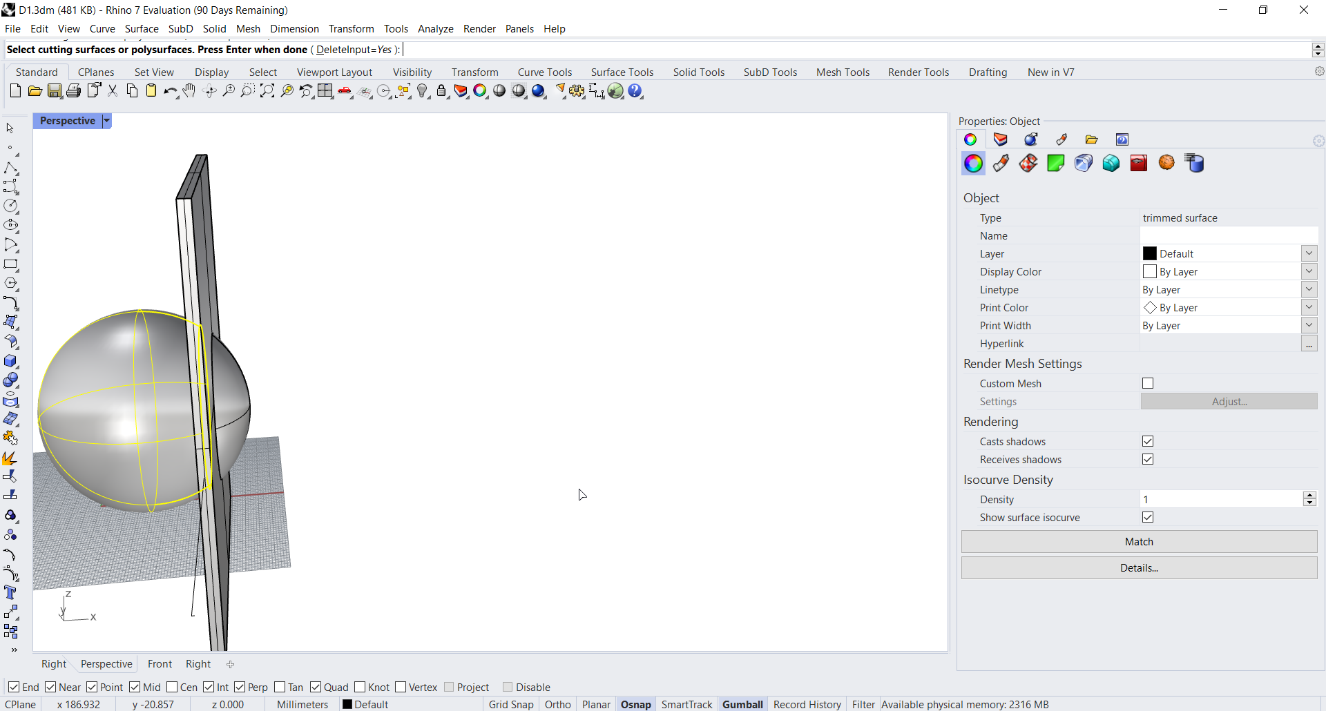
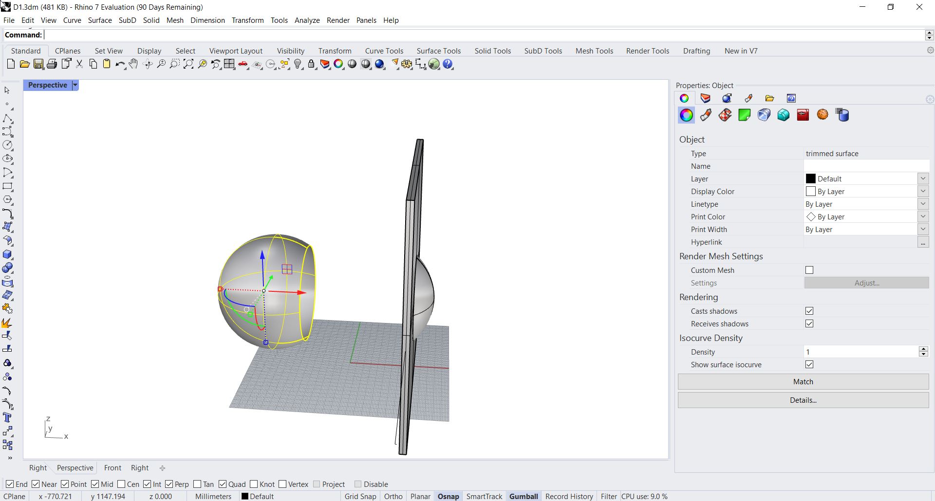
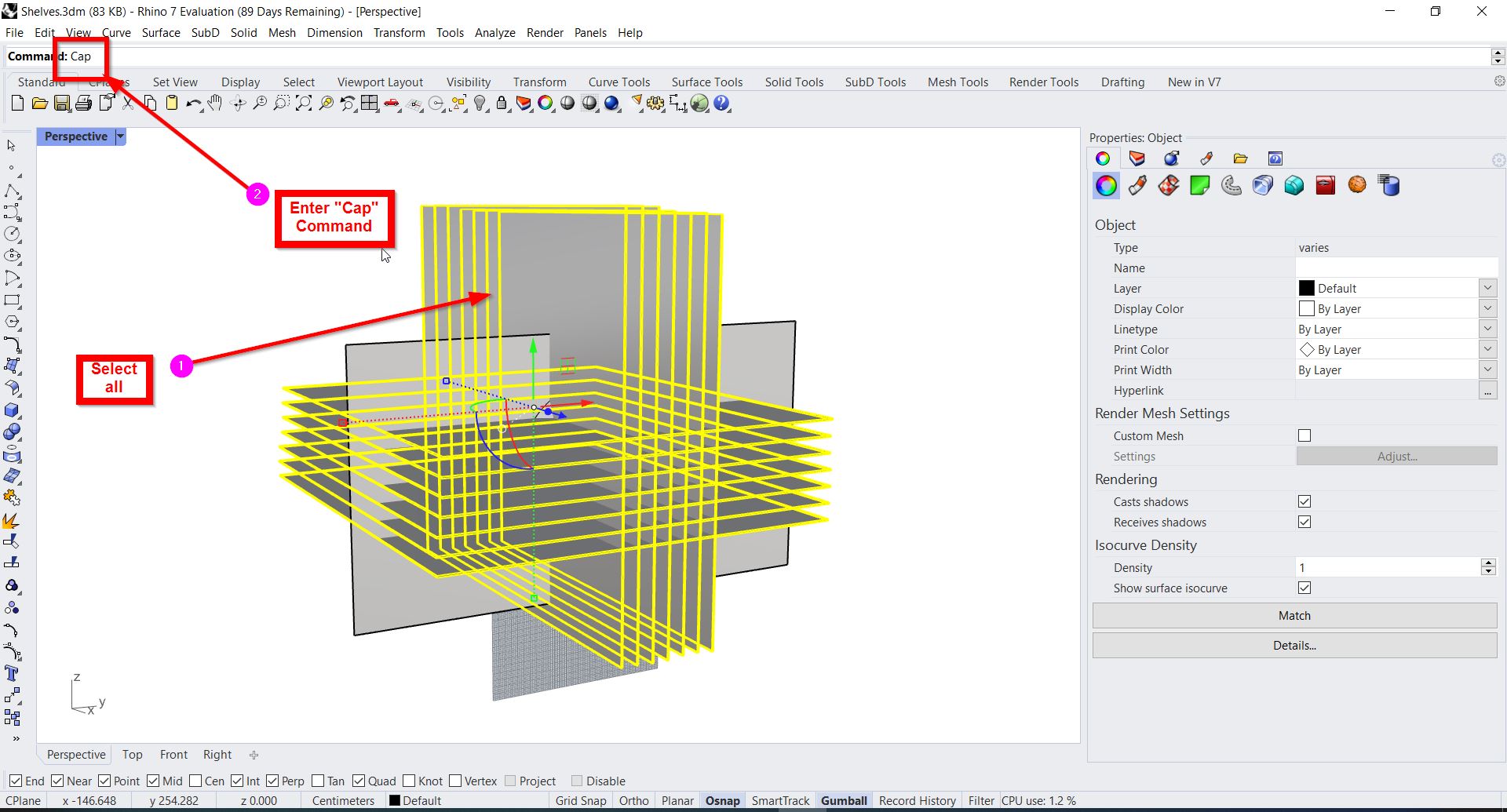
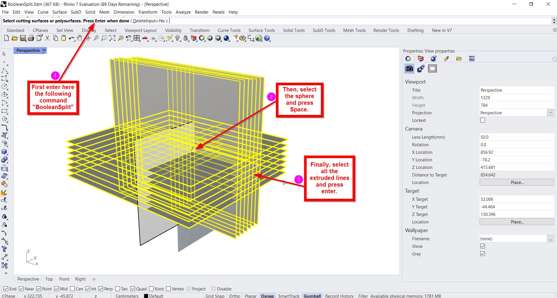
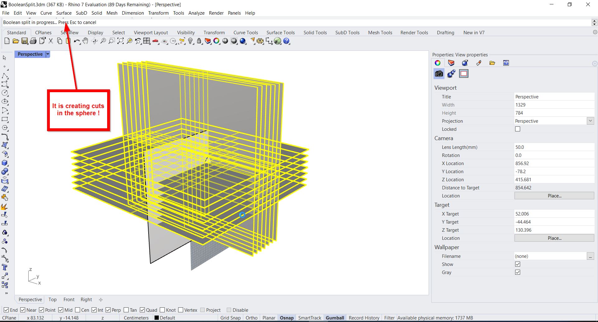
- To cut the unwanted part, “BooleanSplit” command was typed in the command line. Then, the sphere was selected, space was pressed, the wall was selected and ‘enter’ button was clicked:
The final output:
- The wall was deleted and a new one was created:
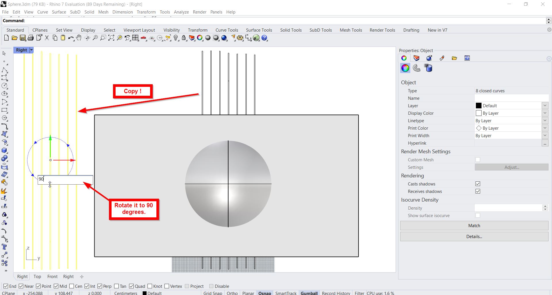
- A rectangle with the desired sizes was drawn and duplicated:
- The rectangles was selected, duplicated, and rotated:
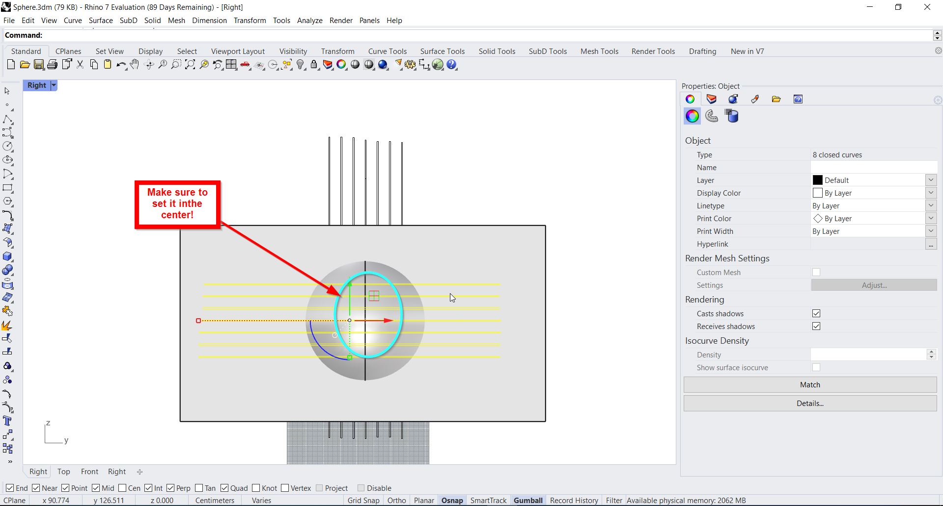
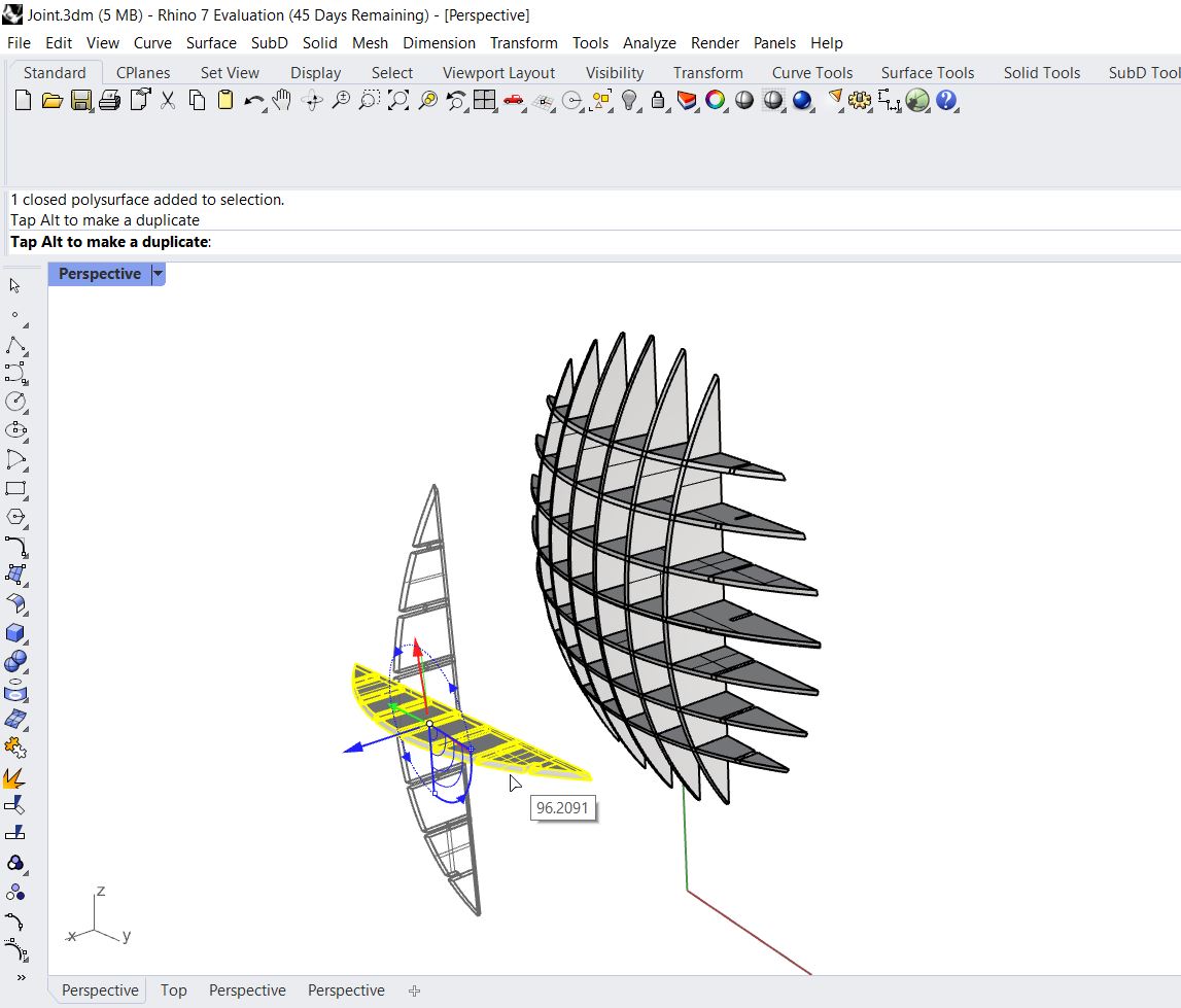
- Alignment the rectangles to be in the center of the sphere:
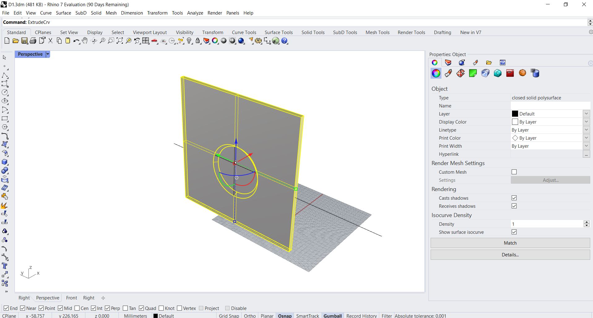
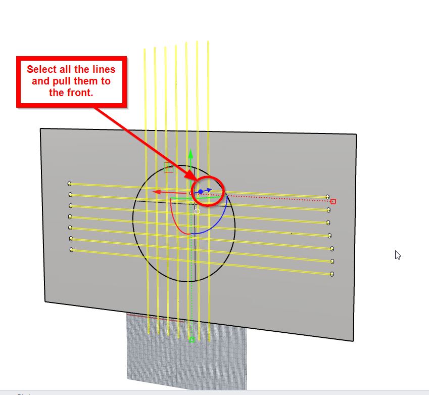
- Move all the rectangles to the front to extrude them:
- Extrude the rectangles and use “caps” command:
- Create the splits on the sphere using “BooleanSplit” command:
The result output would be:
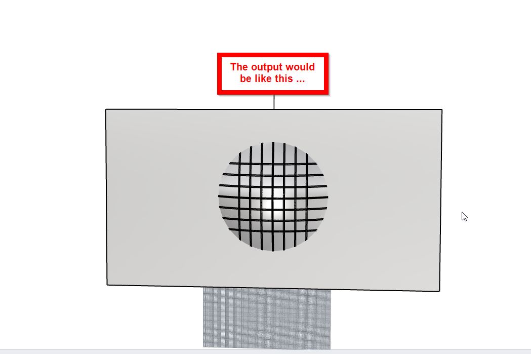
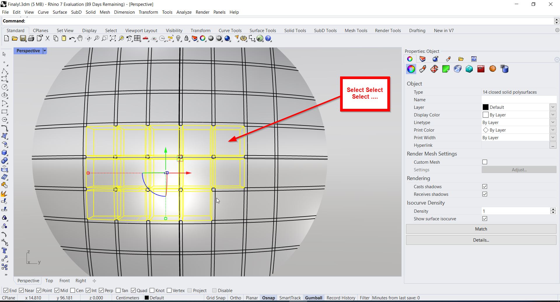
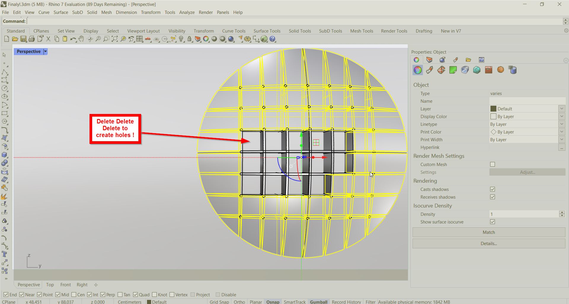
- Remove the extra parts to create holes:
Finally …
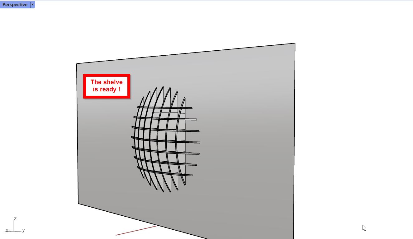
Roll Drams …
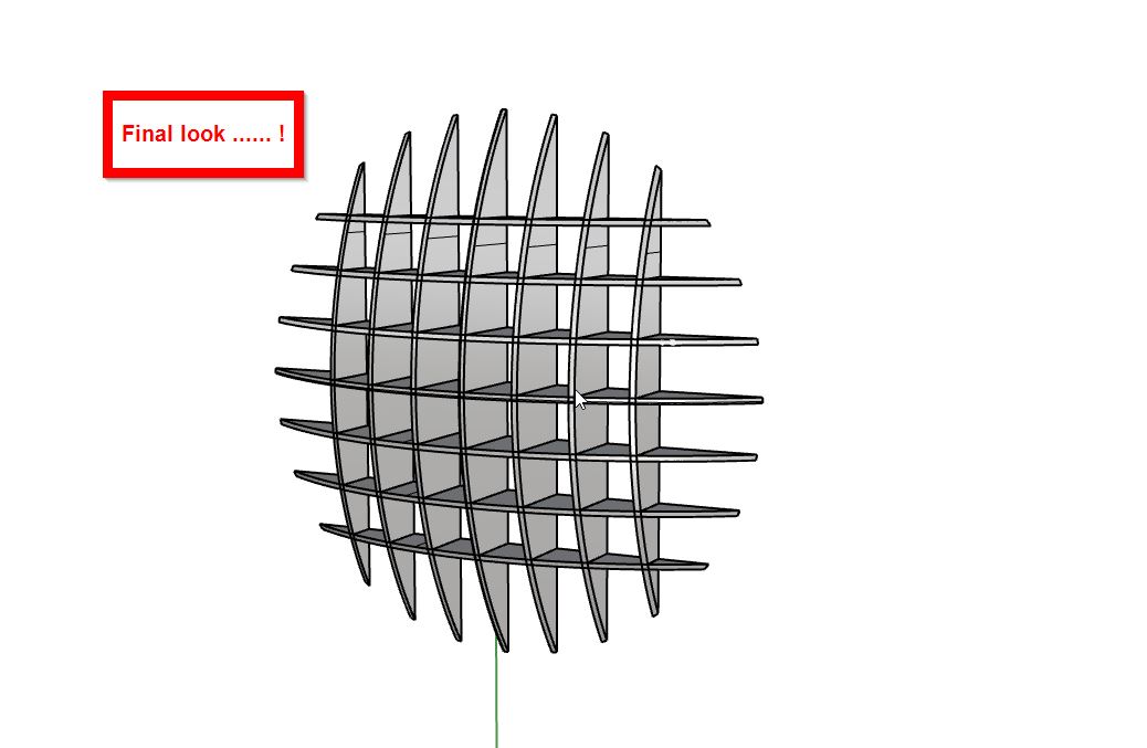
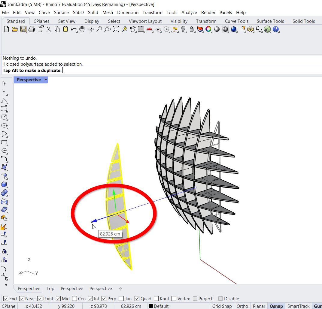
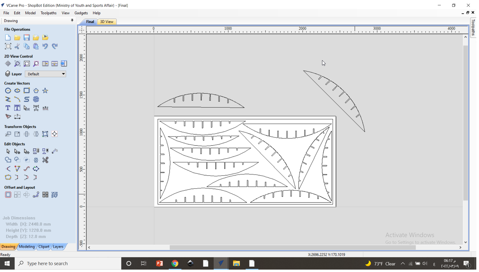
3D Model
Toolpath Phase
Before starting cutting the design, from the toolpath we need to set the cutting modes, sheets sizes, fit all the design in a way to save as much as possible material (ex. wood), and confirm that the design have a tolerance. Therefore, the following steps were achieved:
-
Firstly, VCarve software was downloaded. This software solution is used for creating and cutting parts on a CNC Router.
-
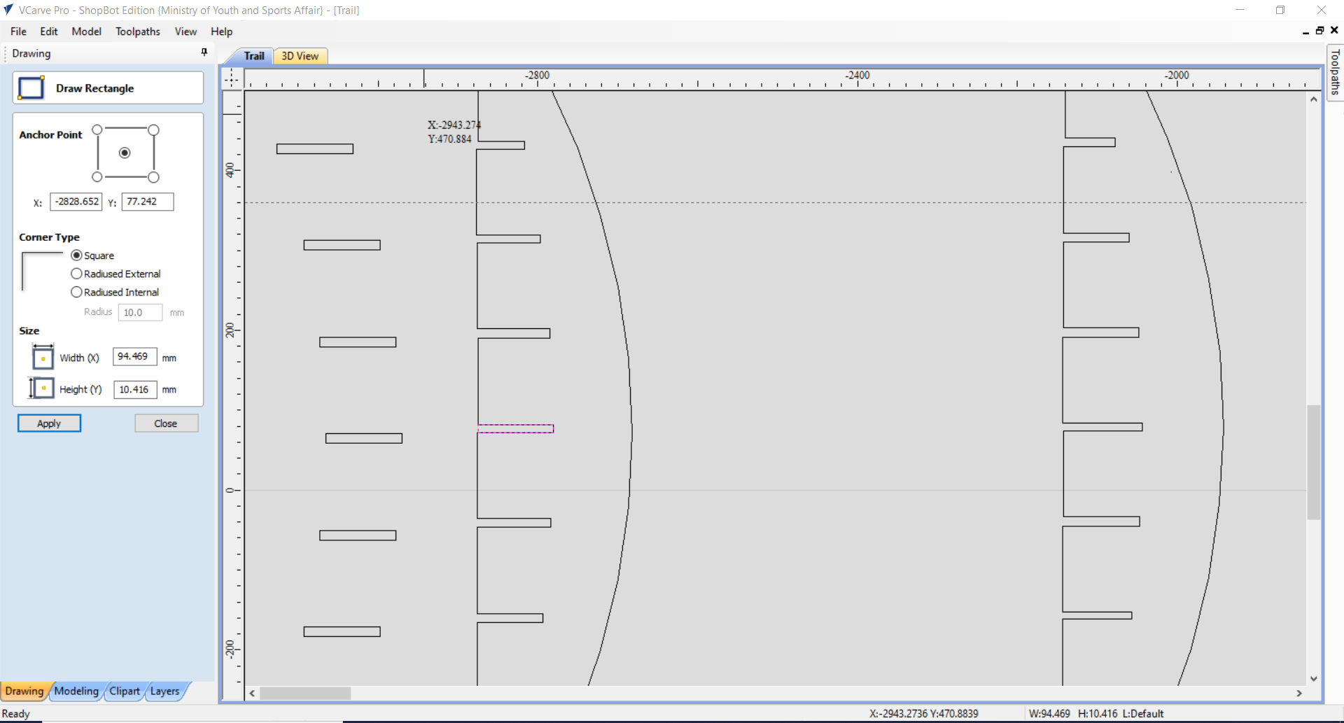
Choose “create a new file” and do the sheet size set up:
- The vectors where imported. From file > Import > Imports Vectors:
After trying to import the parts the following errors were identified:
Error 1 | Parts Joints
When I tried to export each part separately noticed that each and every parts are not grouped as shown below !!!
In addition, I noticed that the their is no joints in the parts. Thus, to over come this issue I did the following procedures:
- First remove the edge part and the joint, and the draw a line in the middle to be extruded.
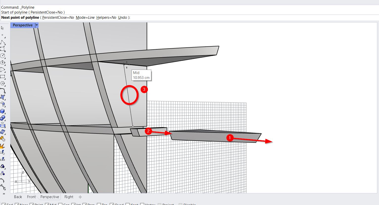
- The line is then extruded to by pass the center of the joint:
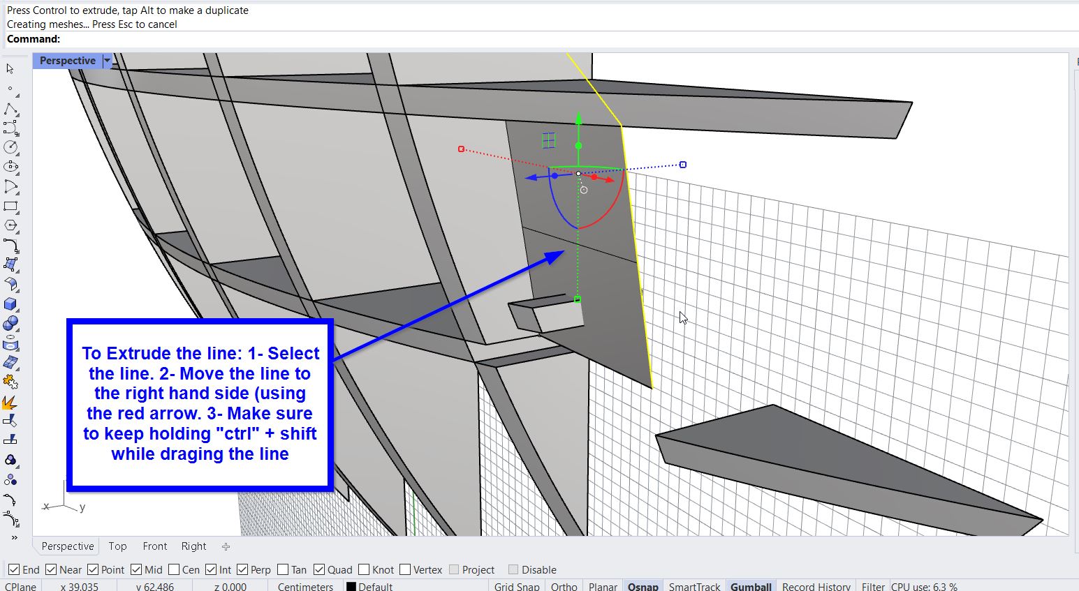
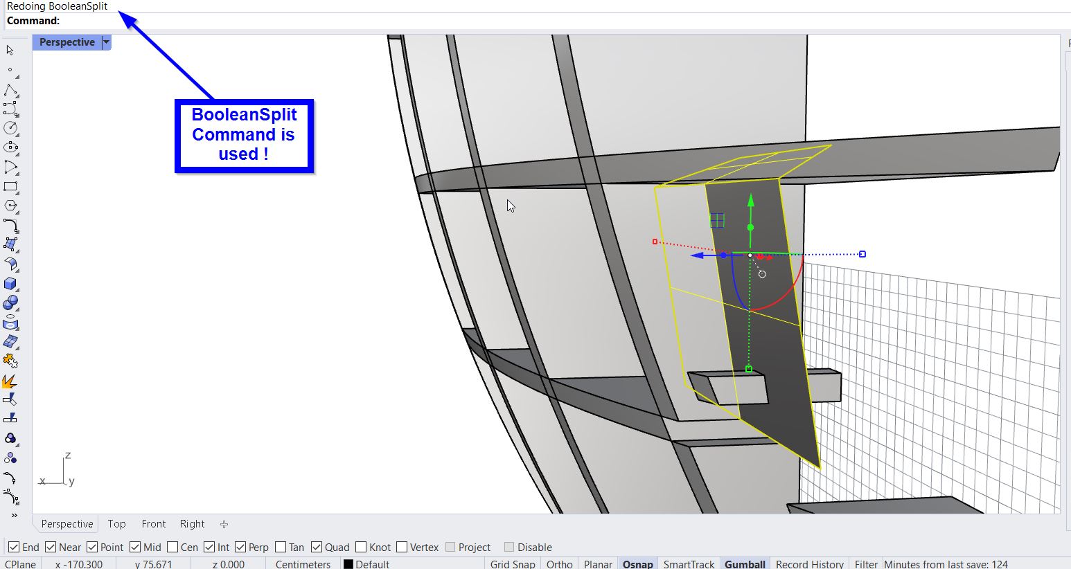
- To split the joint the “BooleanSplit” Command was typed, then the part desired (joint) was selected, enter button is pressed, and finally the extruded line is selected.
- After deleting the extruded line, I moved the joint to its original position. As follows:
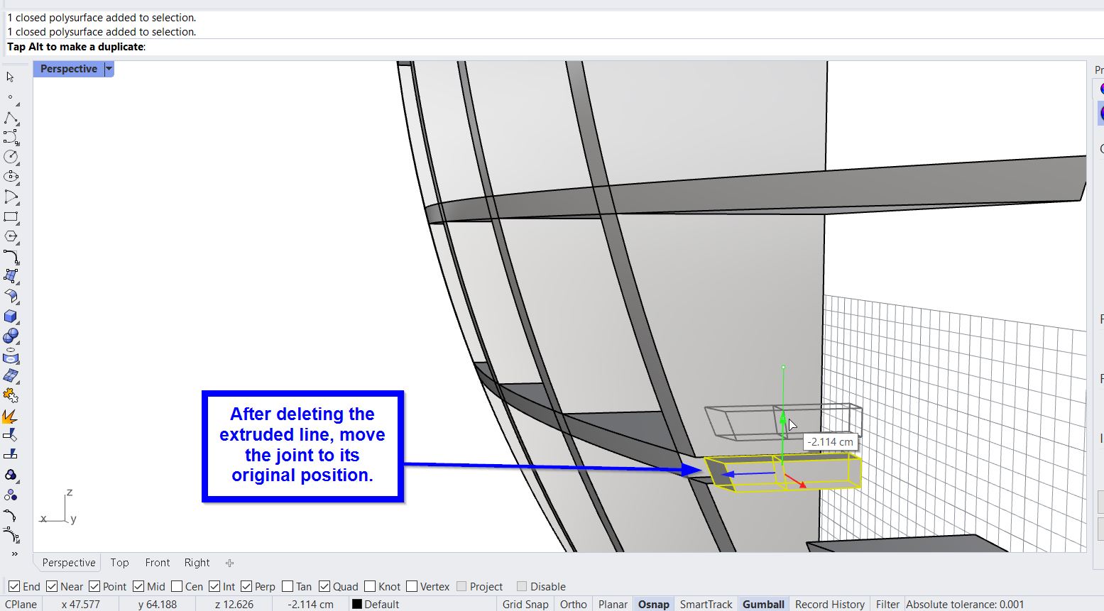
- “BooleanUnion” was typed and the parts that aimed to be grouped was selected.S
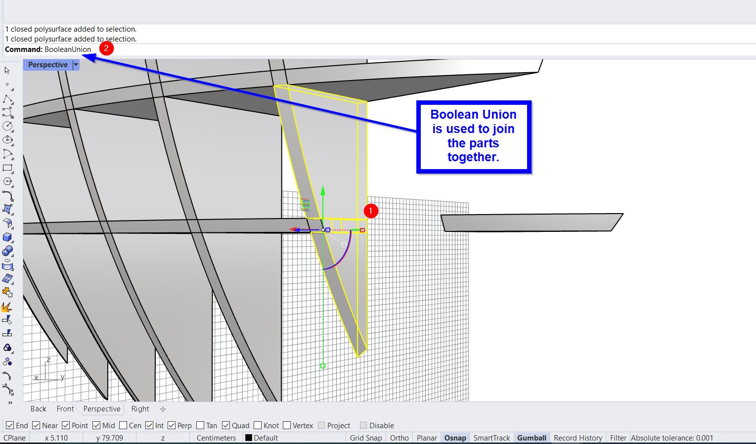
Final Result:
Thus, I repeated the same process multiple of time to create all the design joints and group the parts.
Error 2 | Files Portability
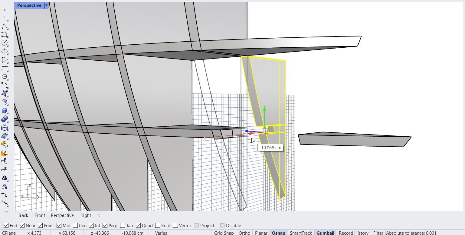
Before using the Rhino7 I searched on the internet to verify that this software can export the equitable format to be imported to the VCarve software. I have noticed that it can export the designs as “.dxf” format. Hence, I started working on it. When I completed the design, the part that were horizontally (on the x-axis) have been successfully imported to the VCarve software. However, for the parts that were sketched vertically (y-axis) they were corrupted because the part are read from the sides. As follows:
Thus, to overcome this issue I have turned the axes of all the parts placed on y-axis to be on the x-axis as follows:
Then, I saved all the part and export them one by one in .dxf format.
Error 3 | Parts Tolerance
The instructor said the designs should be fully tolerance (all the object’s joints are connected to each other). It was preferable to use (0.01) As a tolerance rate to retain the design quality. However, for my design all the joints & parts were not connected as shown below !
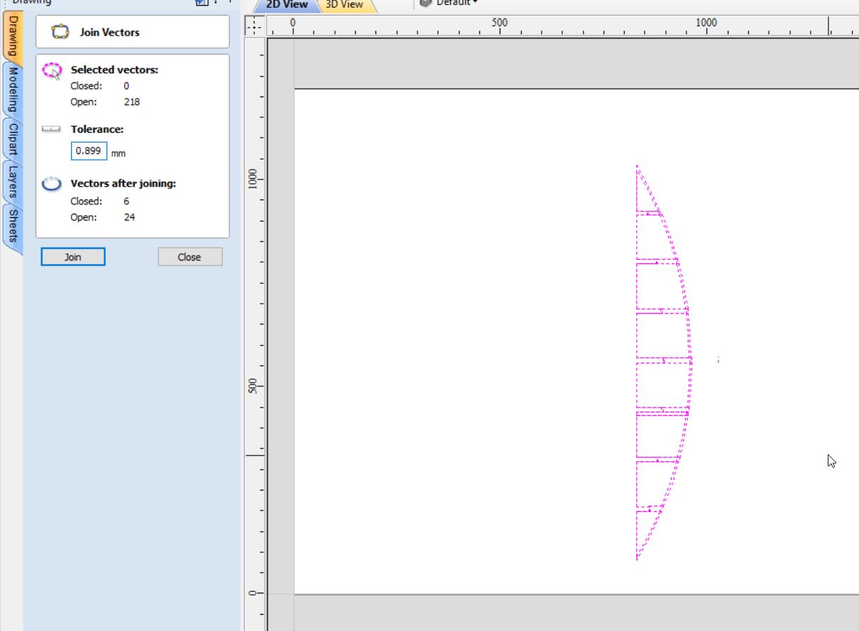
To overcome this issue, I removed all the extra un-wanted lines and for every two points I did tolerance = 0.01.
Error 4 | Parts Alignment
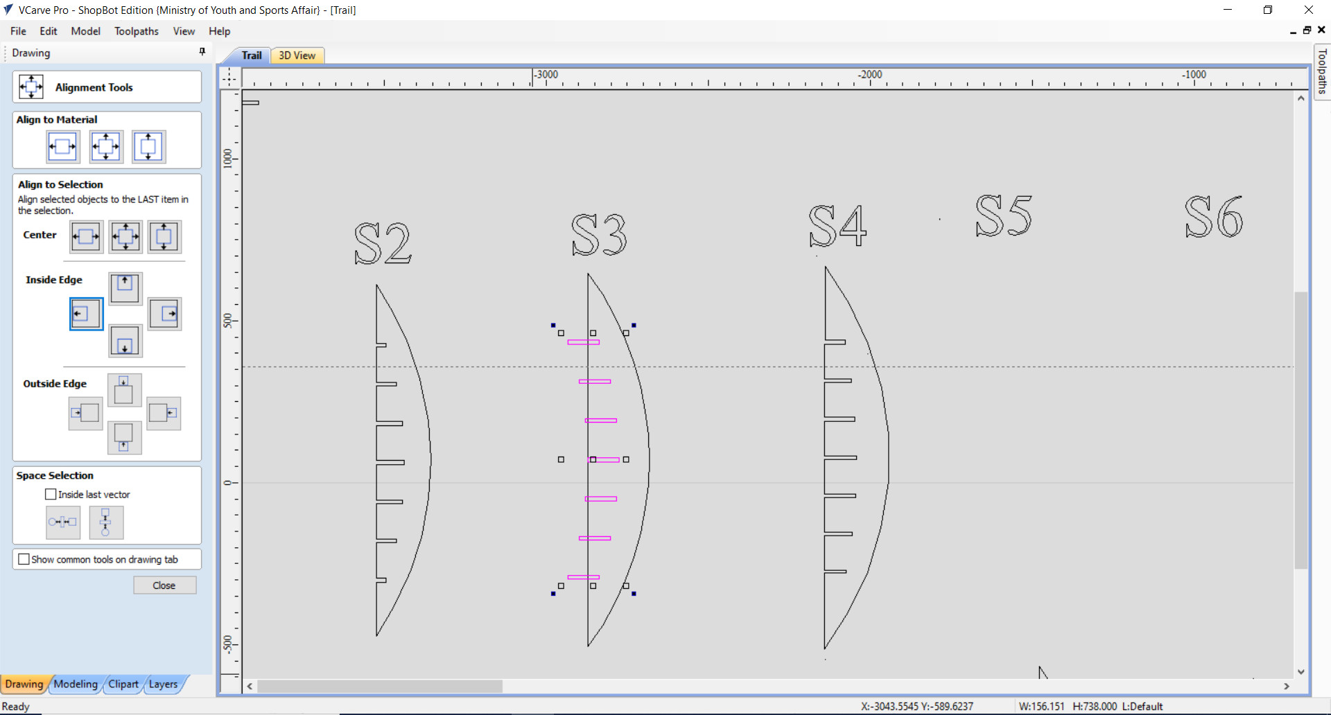
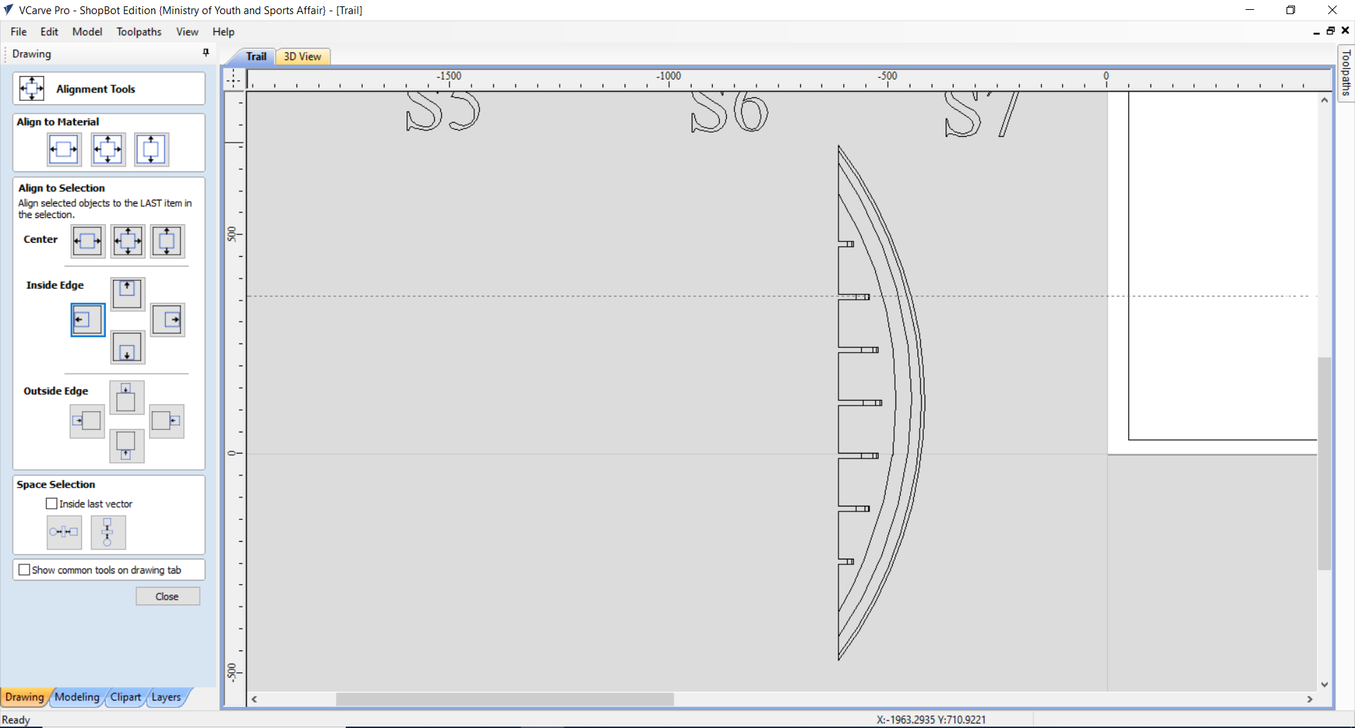
When I completed all the parts’ tolerance, me & my instructor proceeded up to check the parts’ alignment before cutting the parts. To align the parts the following steps were done:
1- Select the objects.
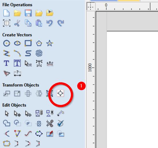
2- Press on the Alignment button show here:
3- Press on the following options:
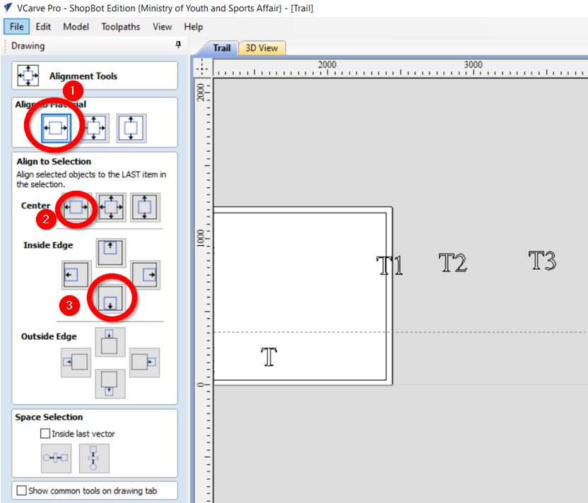
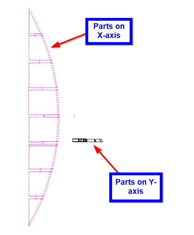
As shown below the parts’ alignment went perfectly for those parts that were on the y-axis.
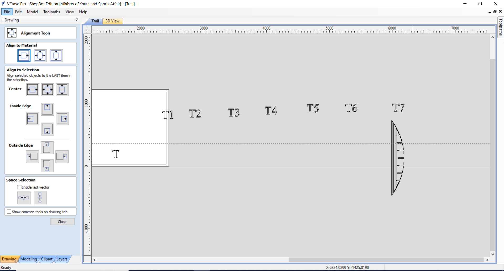
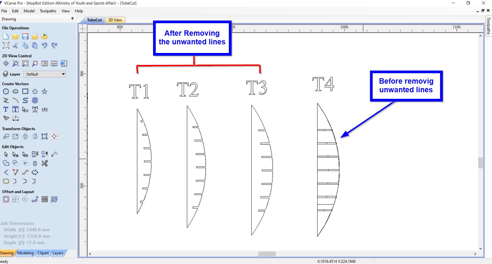
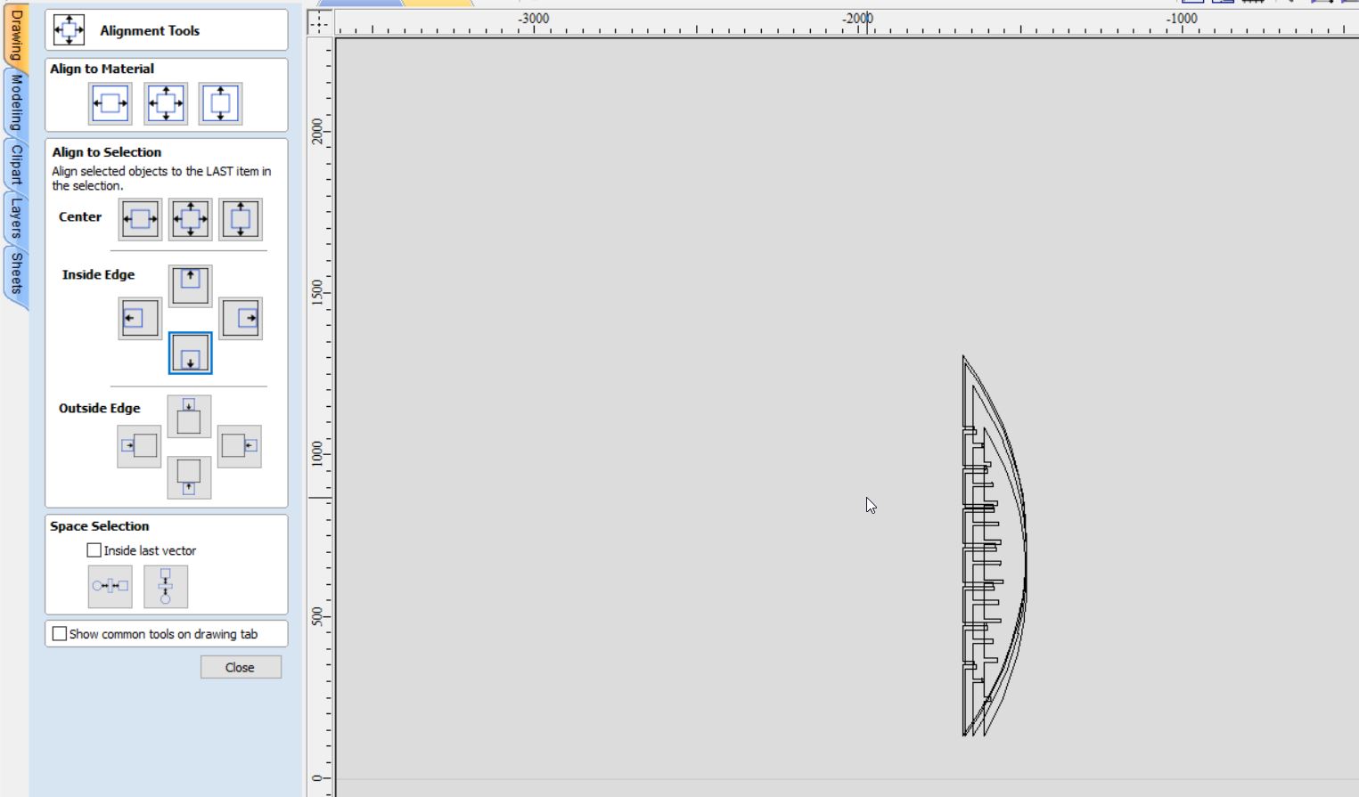
However, we have noticed that for the parts that were placed on x-axis, the parts are not aligned as following:
Hence, to overcome this issue the following steps were accomplished:
- The joints dimensions and gaps were measured. Then, using the squares we have created “joints template” that includes joint with the gaps between them; as displayed in the following image:
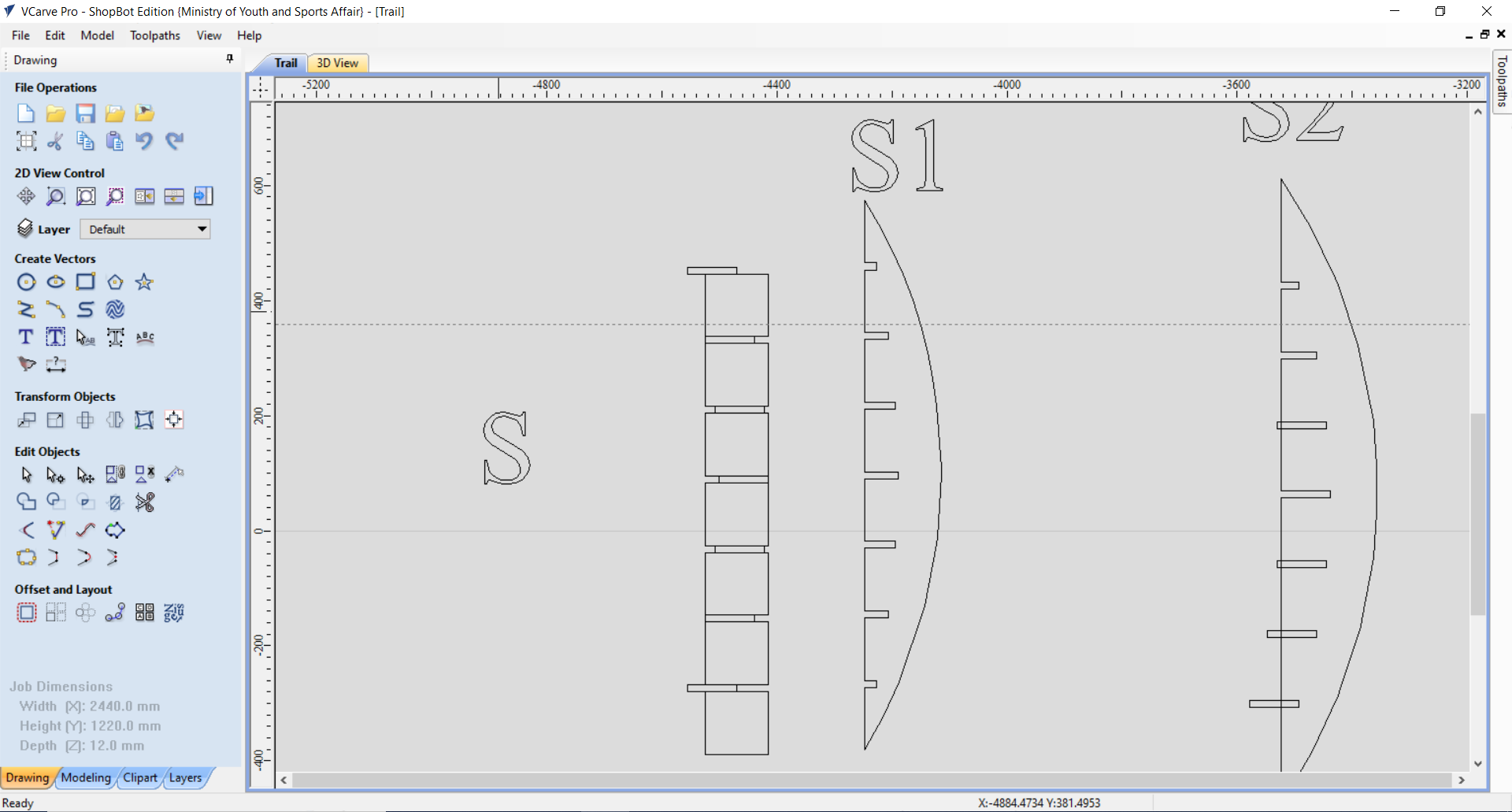
- For each part we have measured the length of the joint (because the joint’s length varies with the different part sizes); and edit the joints’ template.
- New line was drawn to close the curve:
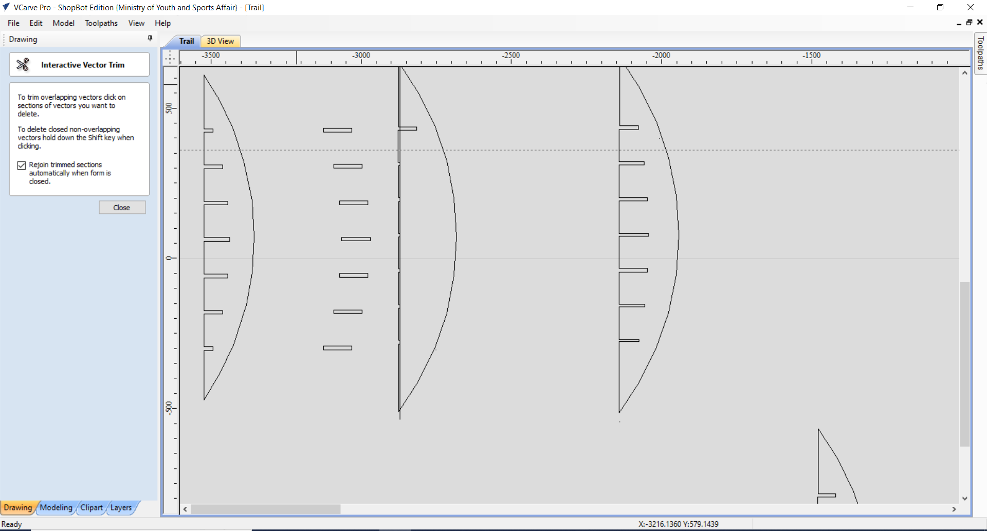
- Then, using the “Trim” tool all the previous joints were removed:
- Then, the new joints were placed on the right place:

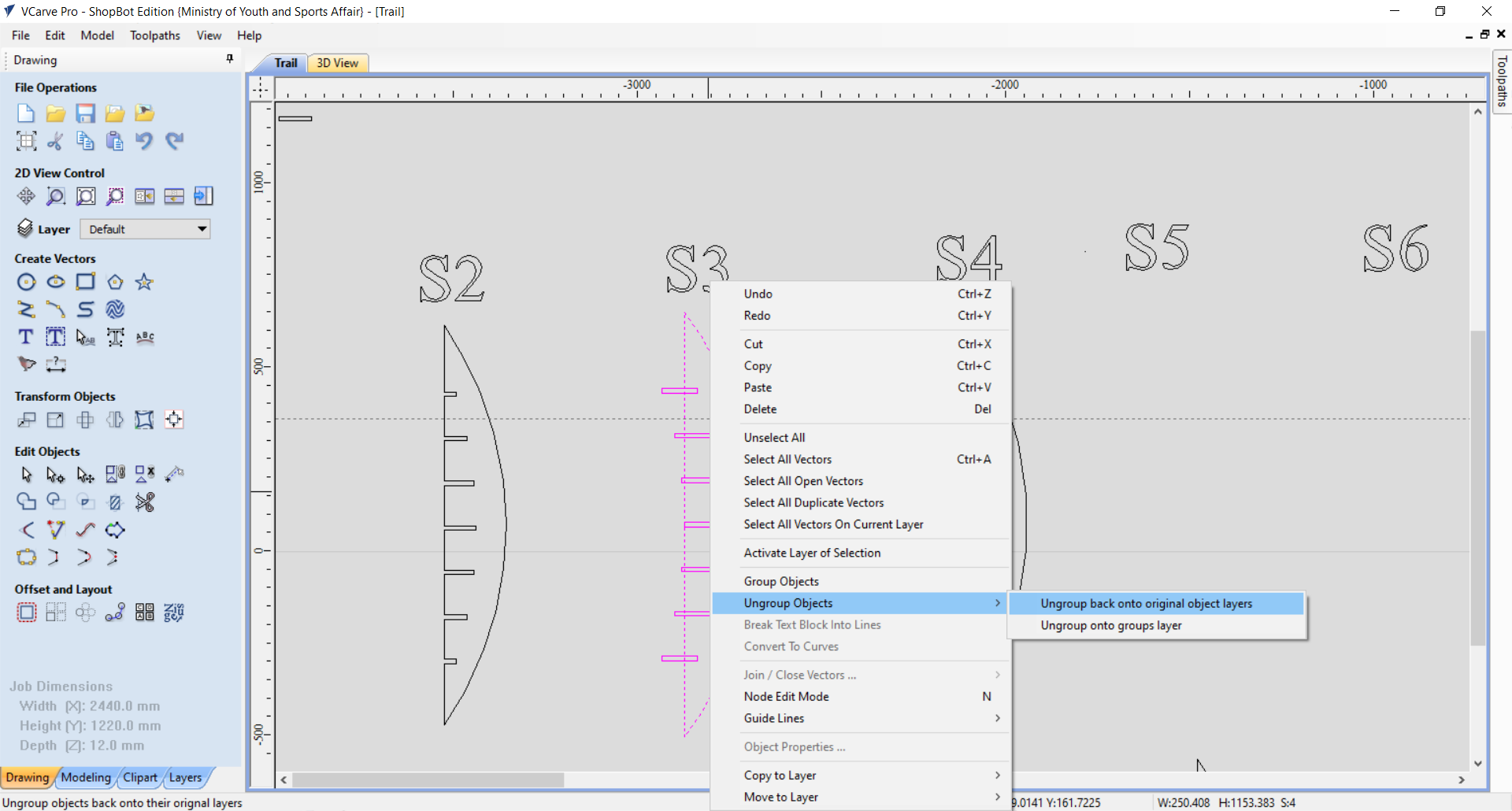
- This the part shape was ungrouped by then grouped again will the new joints:
- I have repeated the same process 4 times only, then for the remaining 3 parts I have used “Mirror” tool to copy the first 3 part as shown here:
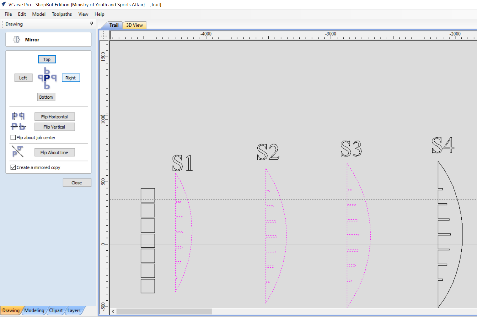
- Afterwards when all of the parts were ready, We aligned the x-axis part together as follows:
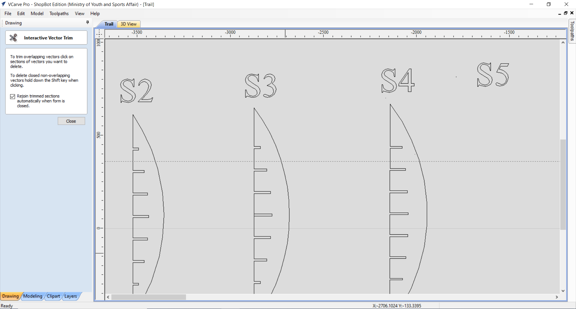
- The parts were then separated and I went ahead by doing the joint fillet using the “Joint” tool and then select the option of “Dog-Bone” fillet:
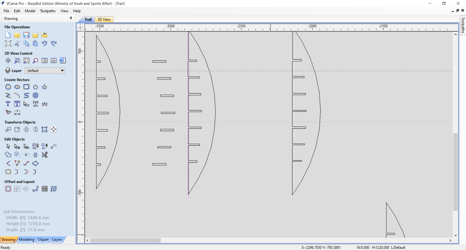
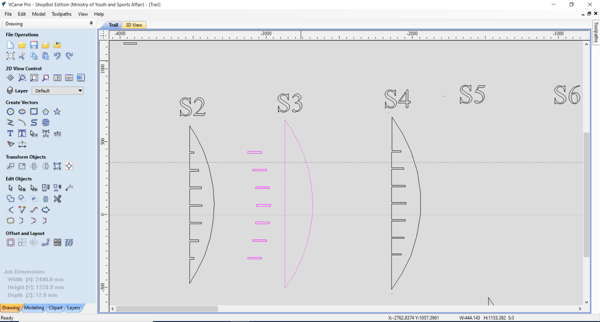
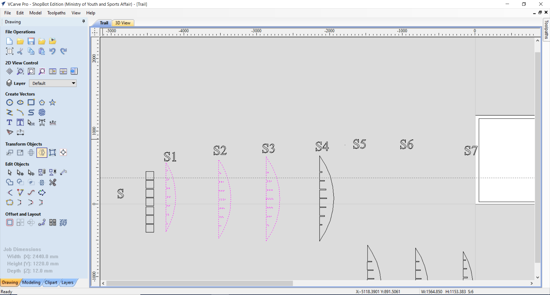
- Finally, all the parts were fit within the sheet to be Cutout:
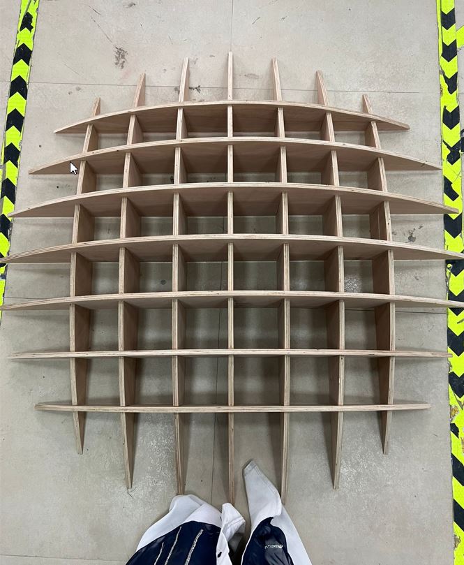
Assembling Phase
For this phase it took me more that 2 hours to complete sanding all the design’s part.
Equipment Used:
1- Sanding Tool
2- Gloves
I did a mini vlog for my assembling process to share it with you. Therefore, please find below my vlog. I hope you enjoy watching it:
Hero Shot
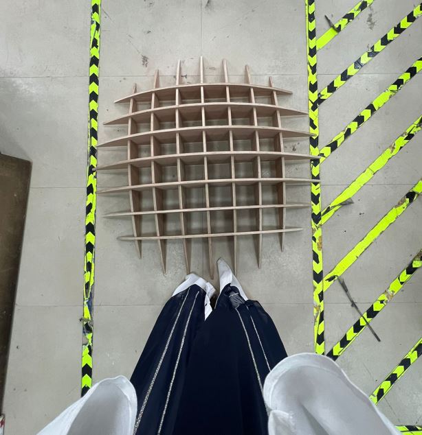
Lets try it out !
Design Files
Download the Design File of each part
Download the design file that is ready to be sent to the CNC Machine
Resources
Thank you for reading !