2. Computer Aided design
This week’s task was to utilize different softwares to make 2D and 3D designs. The 2D designs were made by Microsoft PowerPoint and Adobe Photoshop softwares, whereas the 3D designs were made using Fusion 360 and Openscad softwares.
2D Softwares
Photoshop
Photoshop is a software that is utilized to create and edit 2D designs [1].
Firstly, photoshop was opened and a new document was created. This is illustrated in Fig.(1).
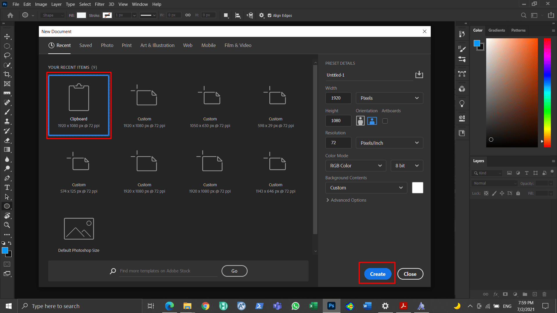
Figure 1: Opening photoshop and creating a new document
The text tool was selected and the words “2D Design” were written as shown in Fig. (2).
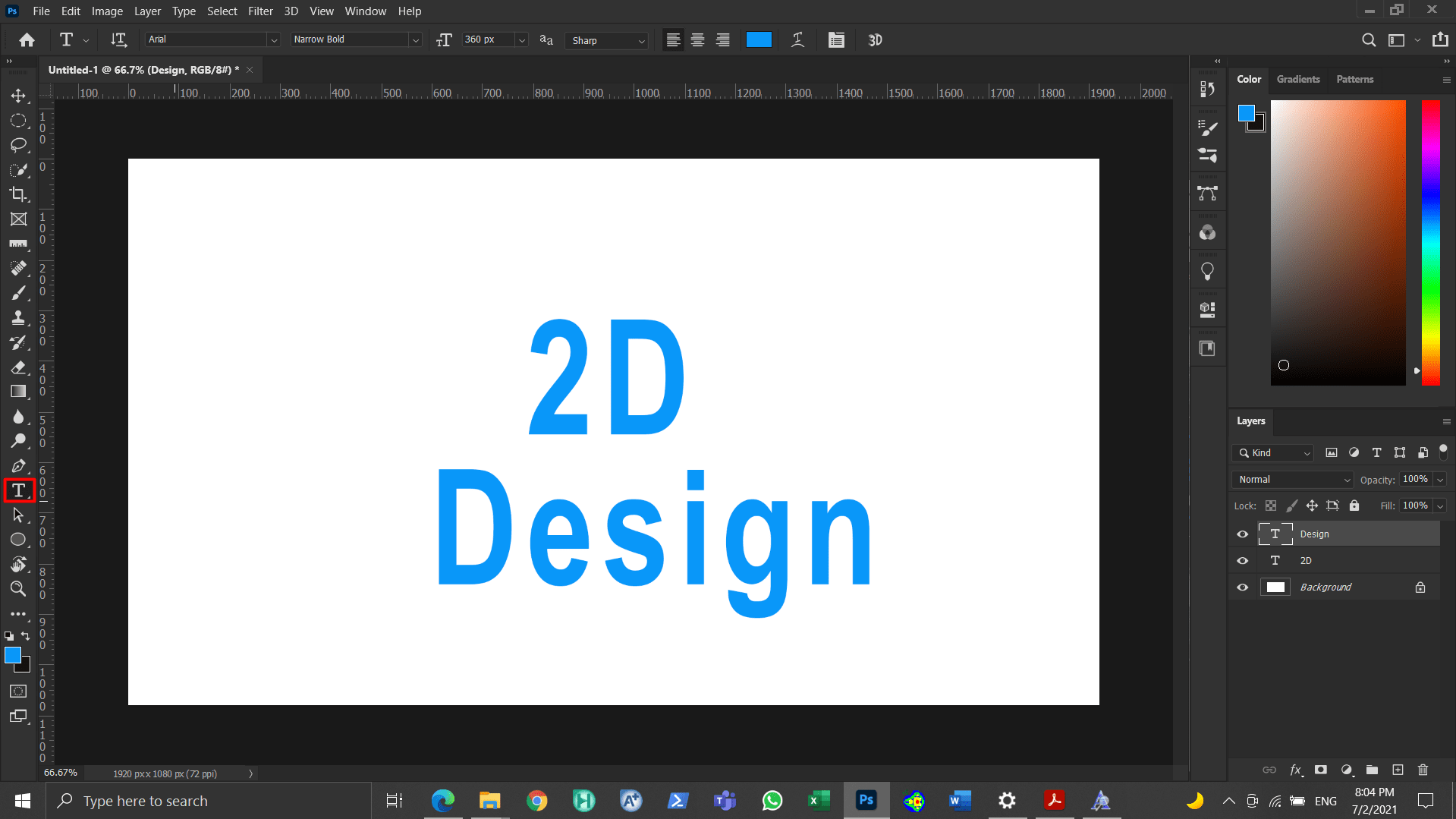
Figure 2: Utilizing the text tool
The rounded rectangle tool was selected, and a rectangle was made around the word Design. This is demonstrated in Fig. (3).
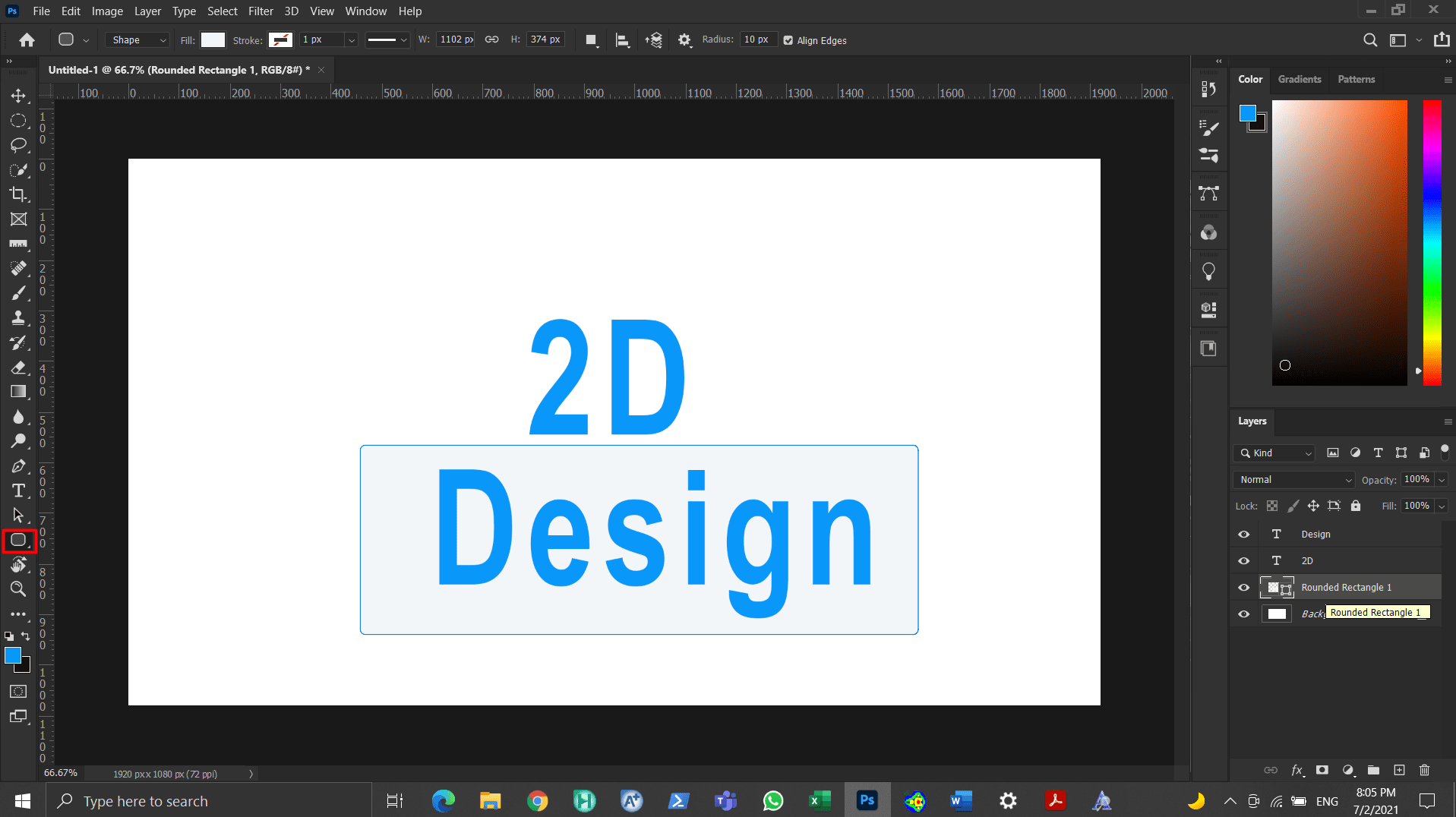
Figure 3: Utilizing the rounded rectangle tool
A stroke for the rectangle was made from the Layer style panel, as shown in Fig. (4).
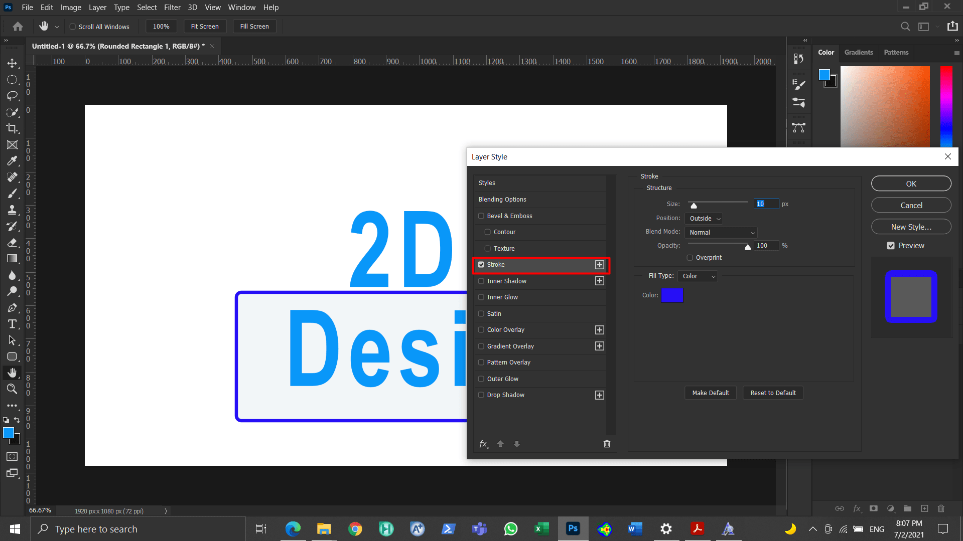
Figure 4: Making a stroke for the rectangle
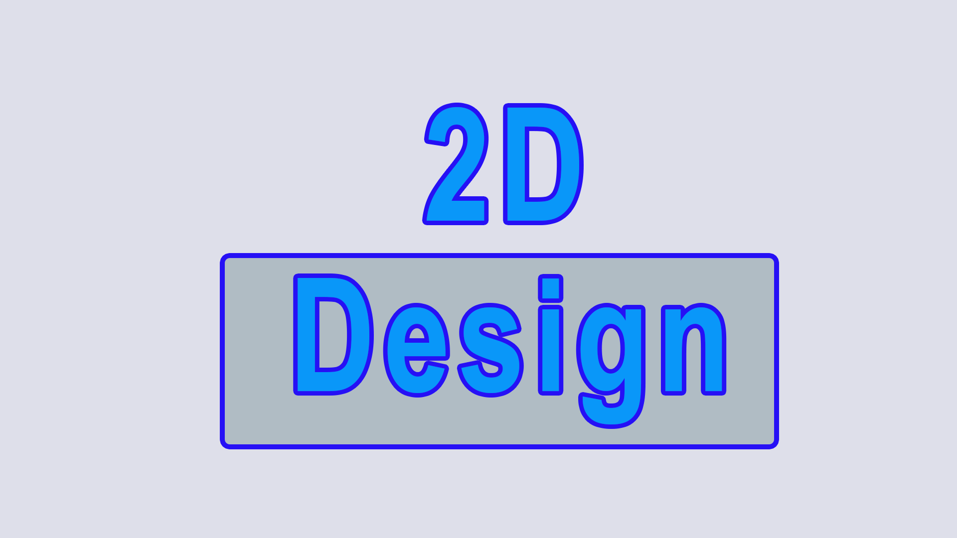
A stroke was added for the words “2D Design”, as shown in Fig. (5).
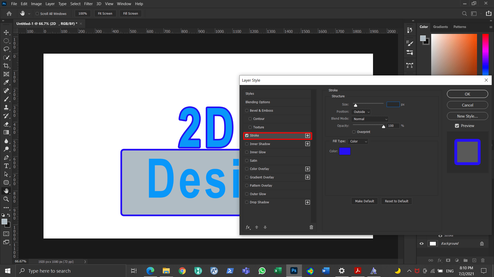
Figure 5: Adding a stroke to the words “2D Design”
The background colour was changed through selecting Layer 0 and pressing Alt+Backspace. This is demonstrated in Fig. (6).
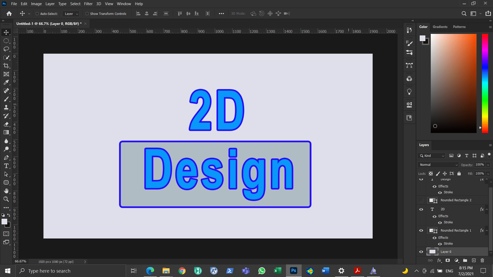
Figure 6: Changing the background color
Powerpoint
Microsoft PowerPoint is a presentation program, but it can be utilized to create 2D designs [2].
Firstly, the option “Rectangle Rounded Corners” was chosen from shapes panel as shown in Fig. (7).
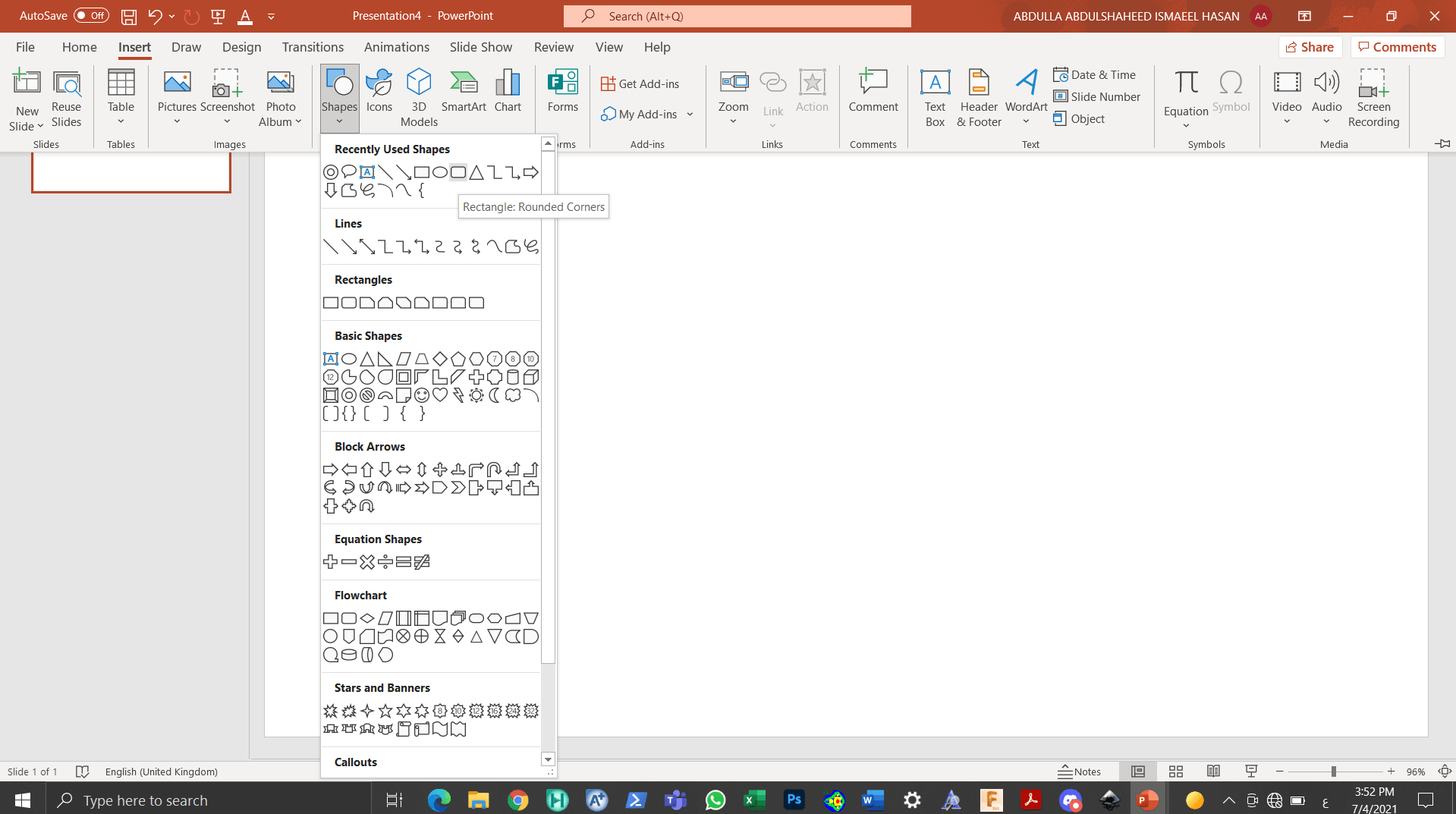
Figure 7: Choosing the option “Rectangle Rounded Corners”
The oval option was chosen and many circles were made as shown in Fig. (8) and Fig. (9).
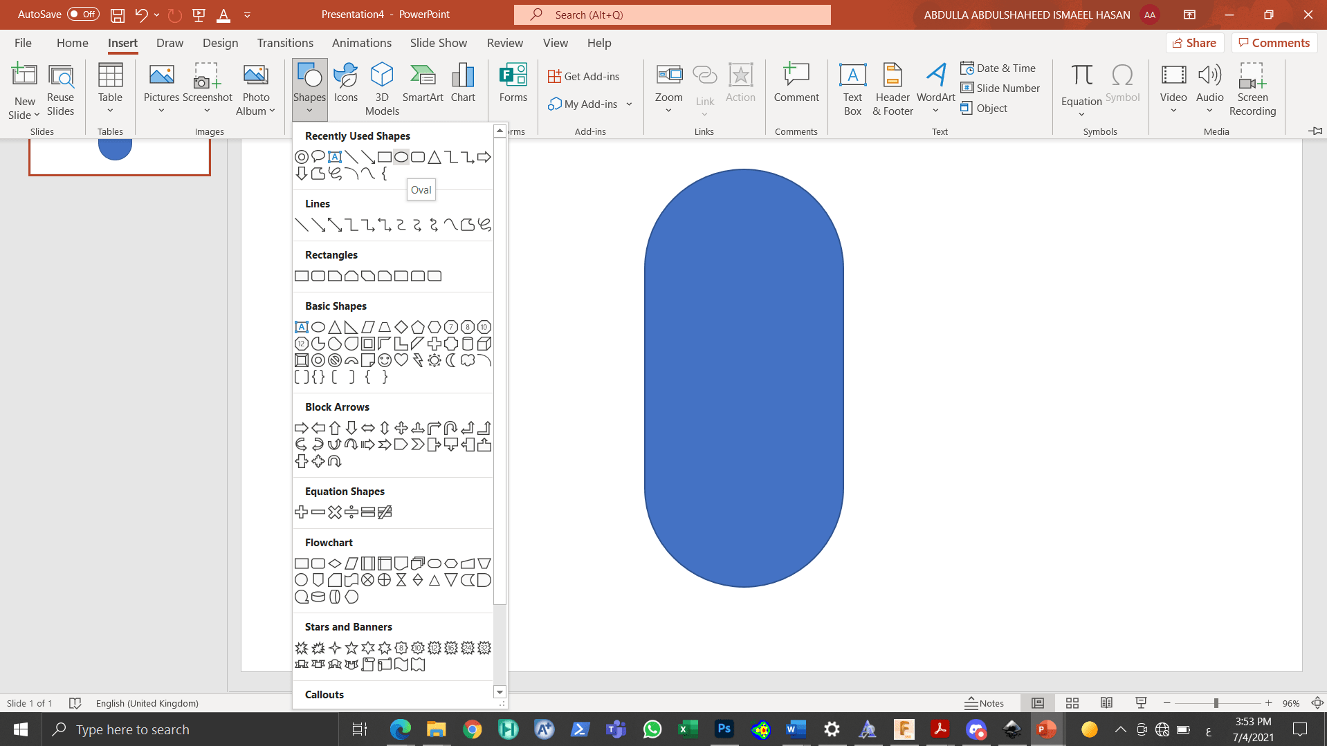
Figure 8: Selecting the oval option
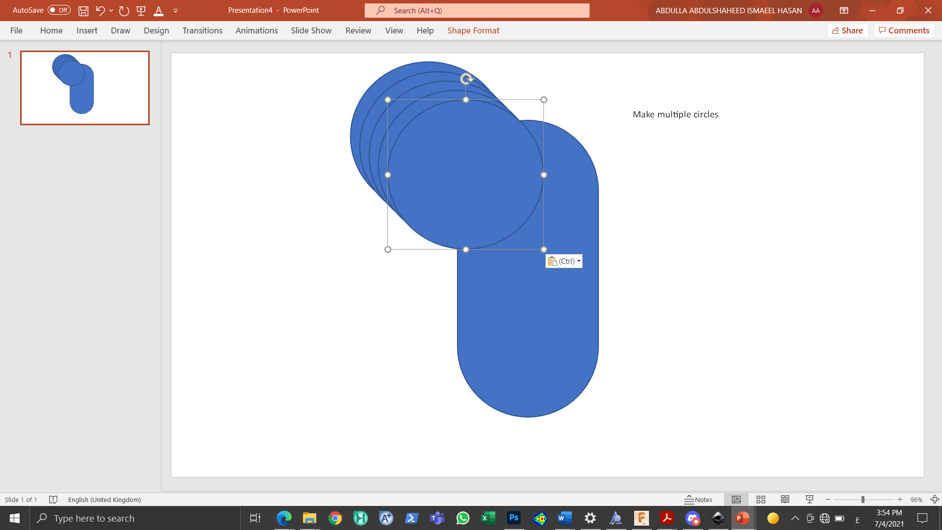
Figure 9: Creating many circles
The circles were arranged on the top of the rounded rectangle as shown in Fig. (10).
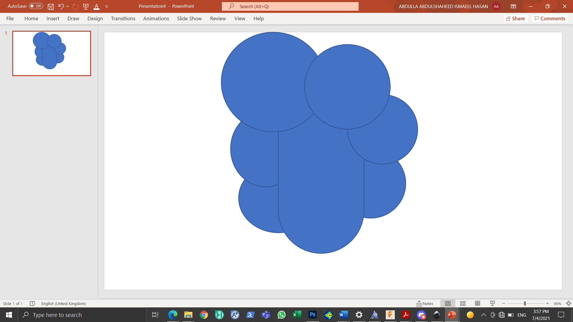
Figure 10: Rearranging the circles on the top of the rounded rectangle
Moreover, colors were added to the design. This is showcased in Fig. (11).
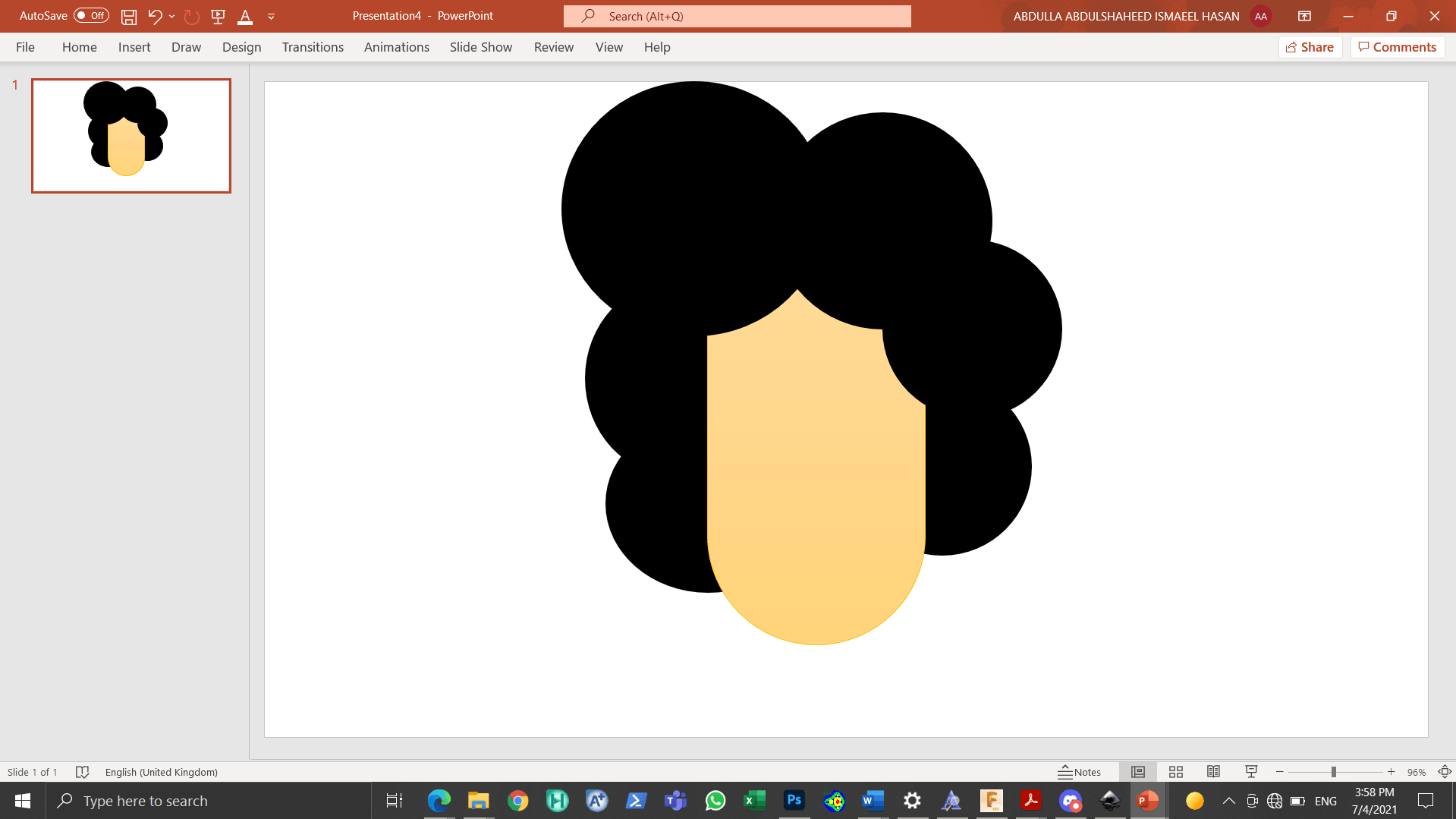
Figure 11: Colors added to the design
The hollow circle and rectangle tools were selected and glasses were made with the help of them. This is shown in Fig. (12), Fig. (13) and Fig. (14), respectively.
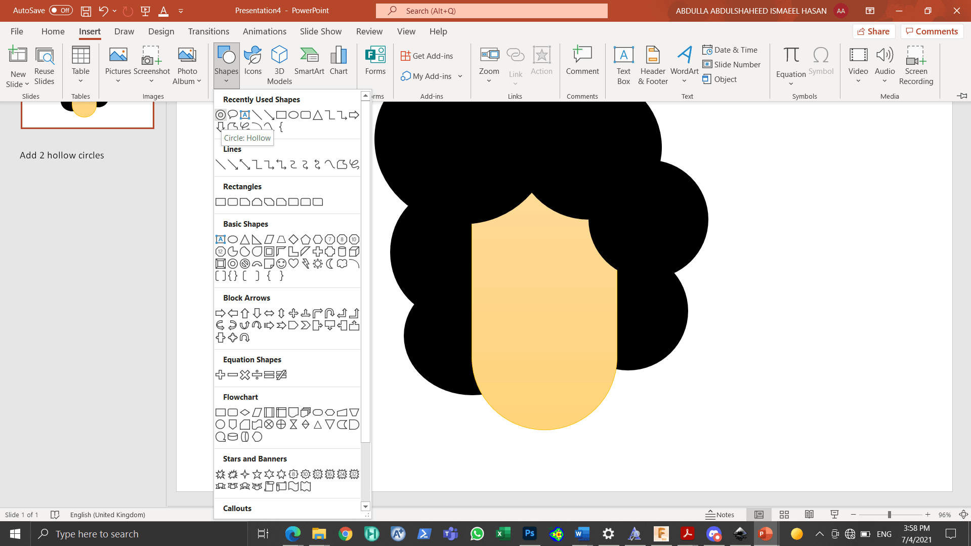
Figure 12: The hollow circle tool selected
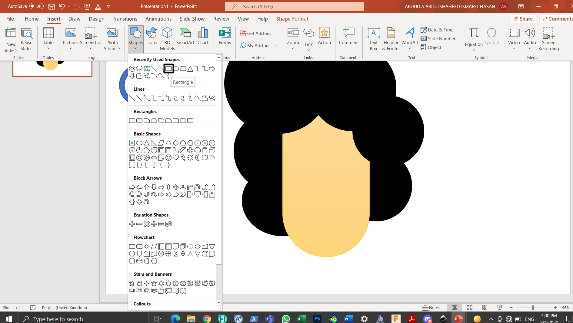
Figure 13: The rectangle tool selected
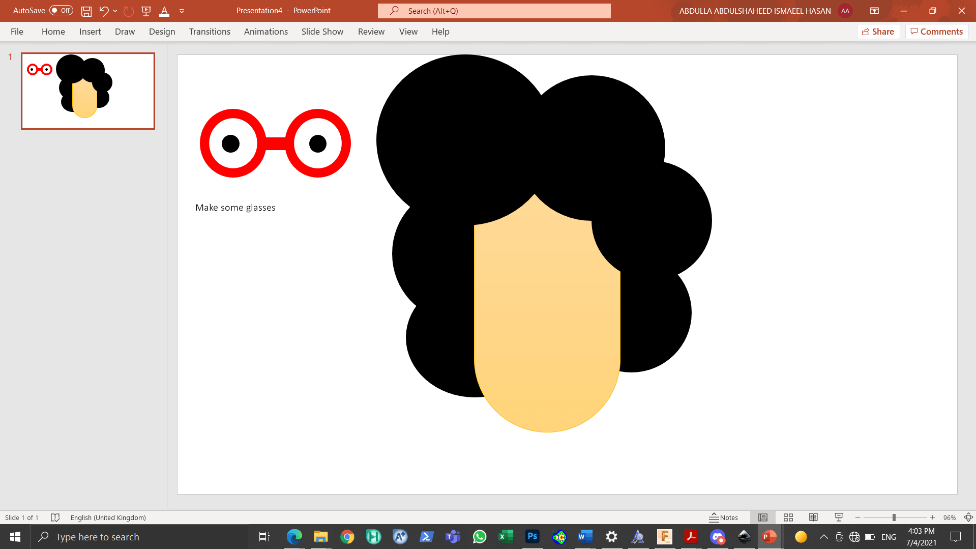
Figure 14: Glasses made with the help of the hollow sphere and rectangle tools
Moreover, the delay function was selected and a mouth was made. This is showcased in Fig. (15) and Fig. (16), respectively.
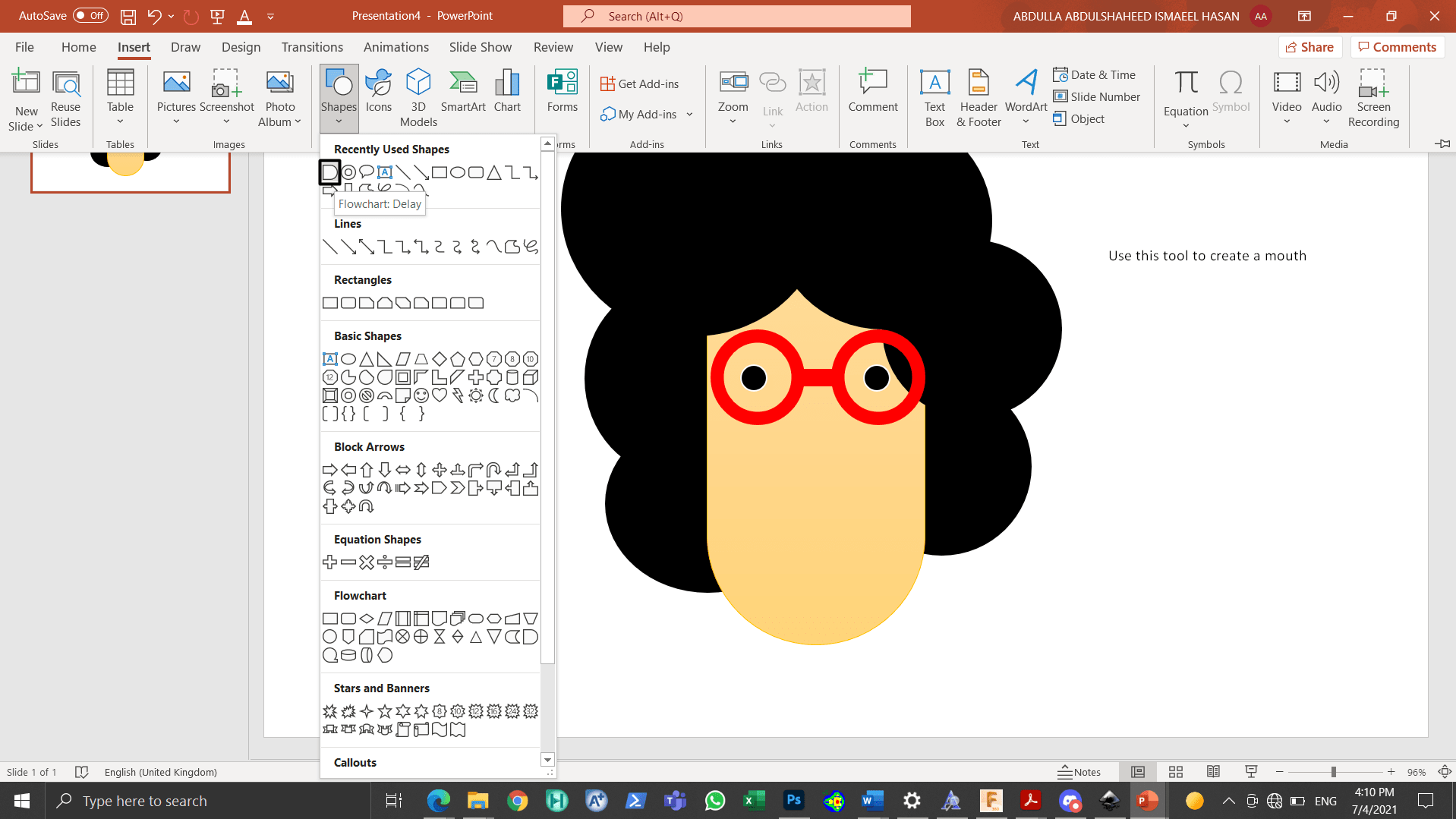
Figure 15: The delay function selected
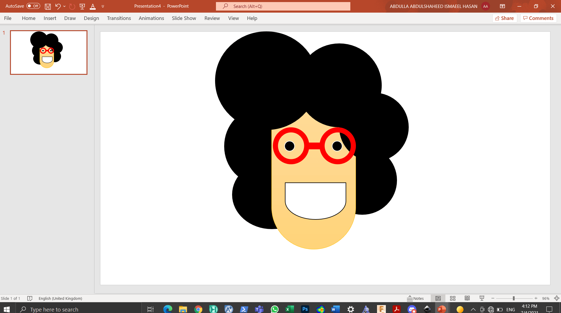
Figure 16: Mouth made and placed on the design
3D Softwares
Fusion 360
Fusion 360 is a software that was developed by the famous company “Autodesk” and can be utilized to make different 3D designs [3].
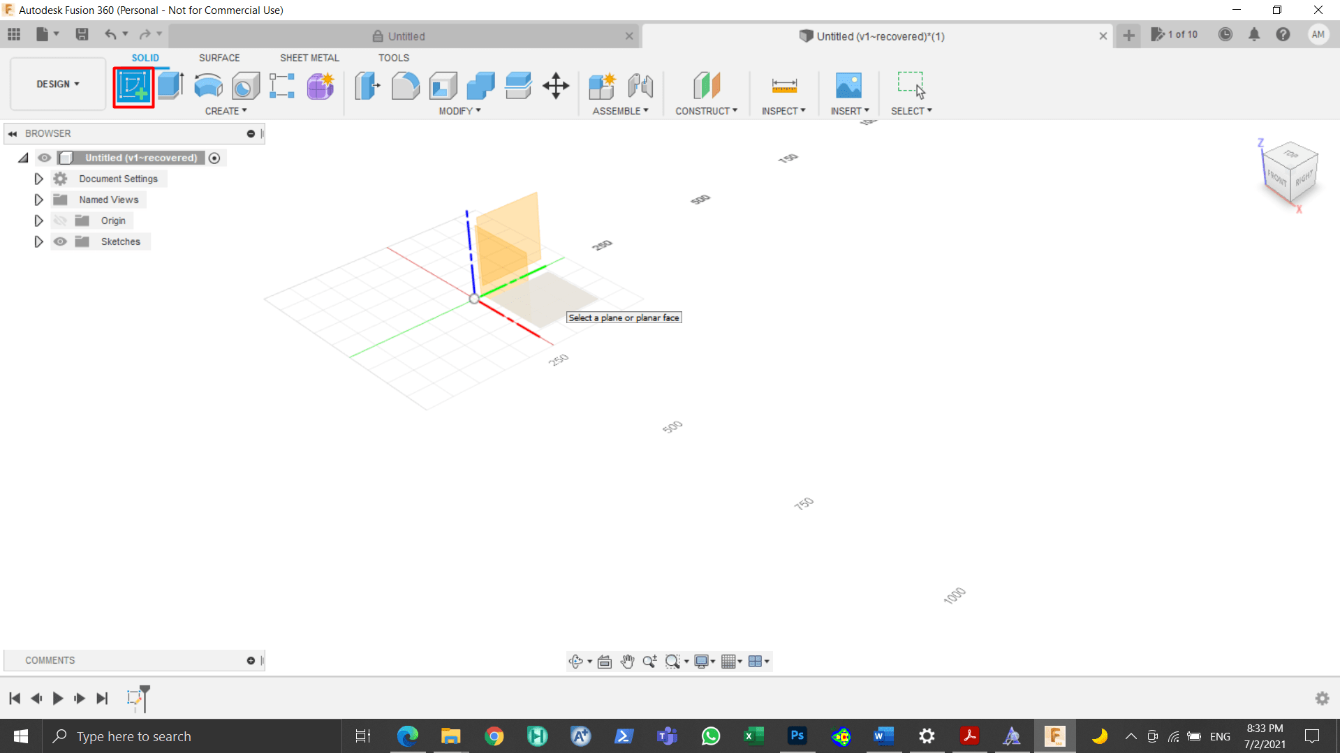
Fusion 360 was opened and the “create sketch” function was selected and the desired plane at which the design will be done on was chosen. This is shown in Fig. (17).
 The “center rectangle” tool was chosen and the rectangle was sketched, as shown in Fig. (18) and Fig. (19), respectively.
Figure 17: Selecting the “create sketch” function and choosing the desired plane.
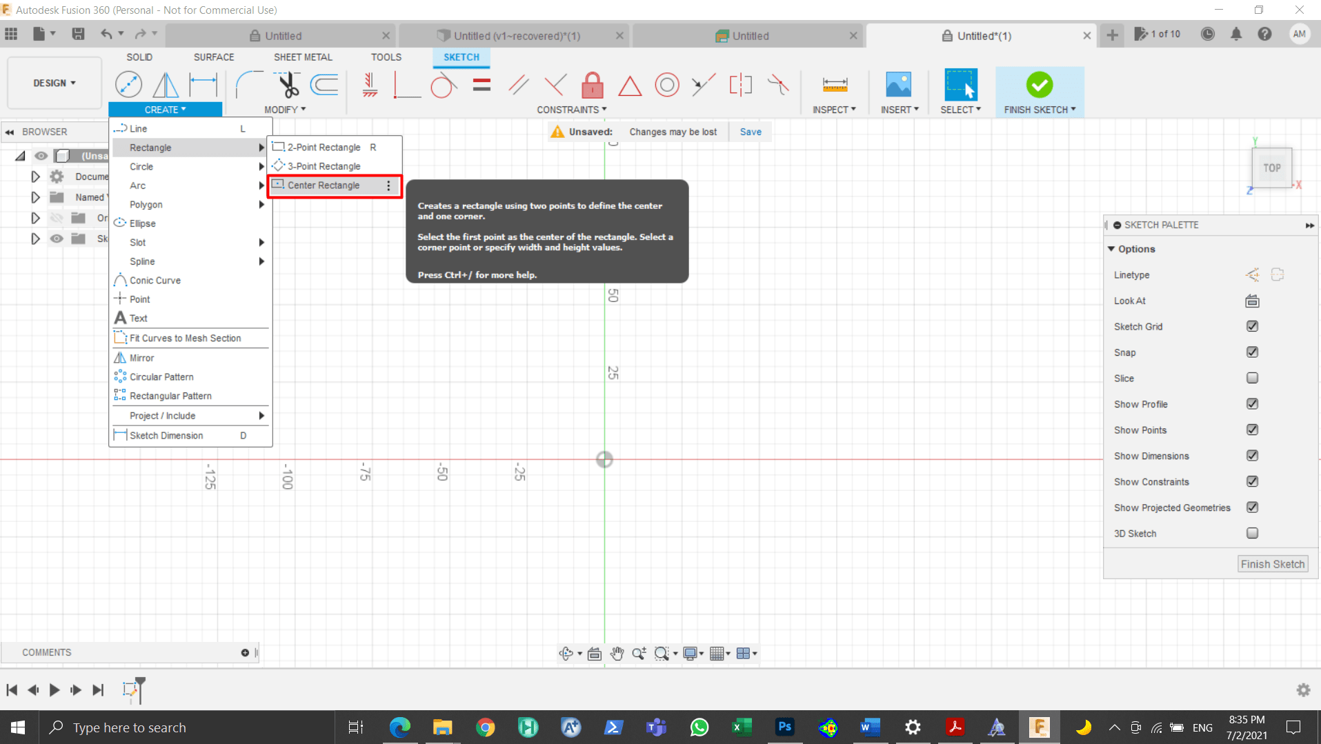
Figure 18: Selecting the “create sketch” function
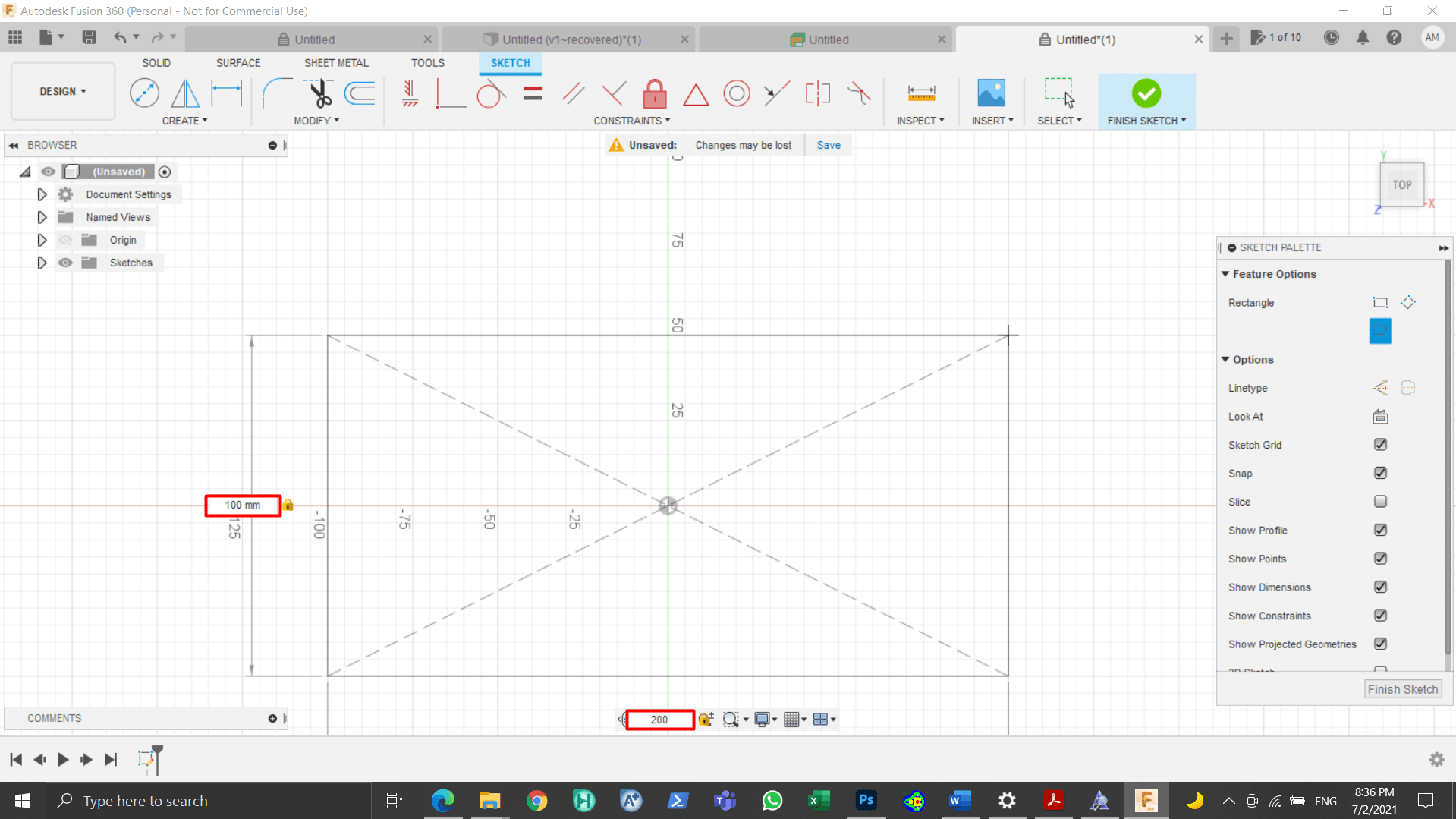
Figure 19: Sketching the rectangle
The “Finish Sketch” function was chosen as shown in Fig. (20).
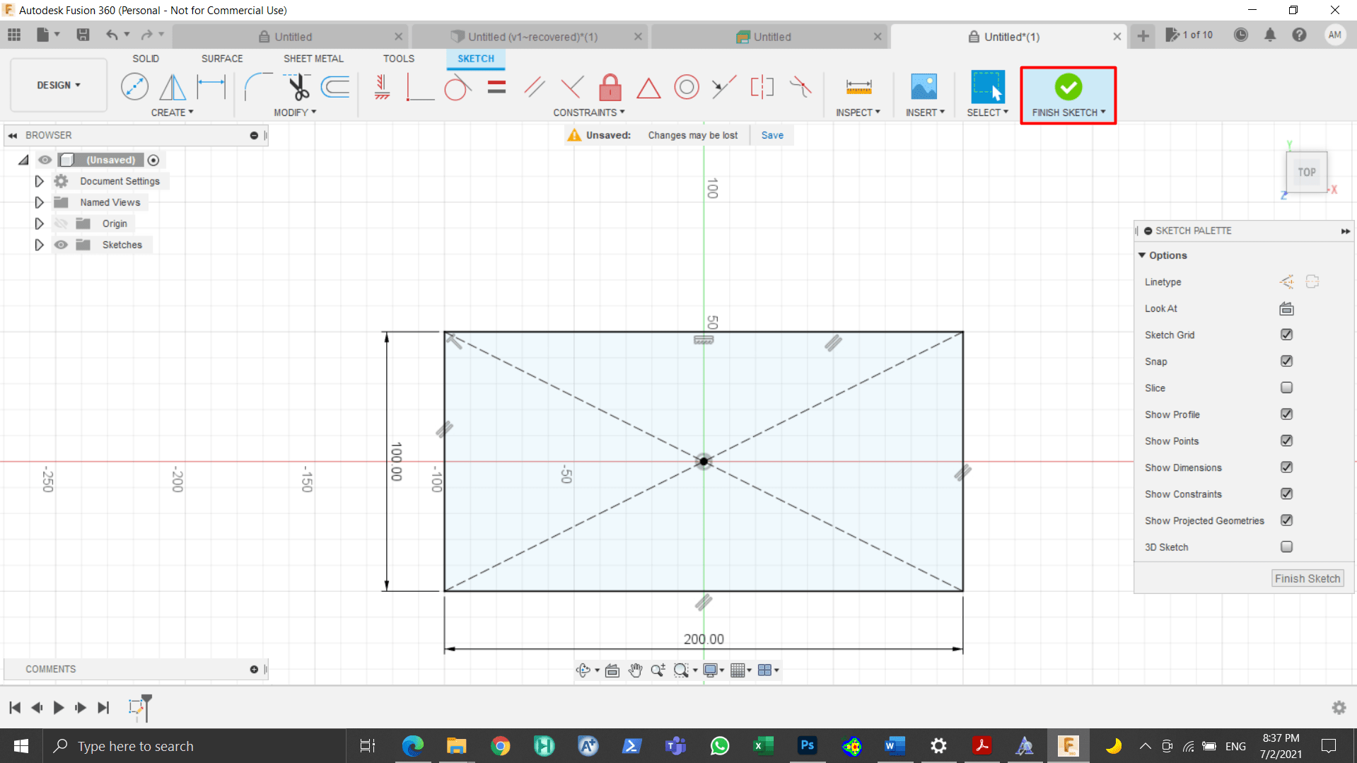
Figure 20: The “Finish Sketch” function
The “Extrude” function was chosen and the arrow was pulled upwards and the 3D shape was created as shown in Fig. (21).
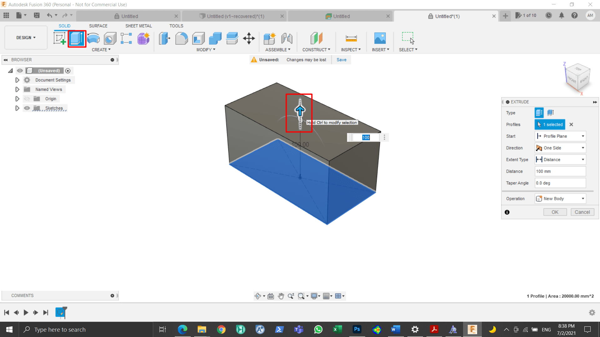
Figure 21: Extruding the rectangle
The “Shell” function was selected and the upper portion of 3D design was chosen in order to make the upper part of it open and the thickness was set as 5 mm. This is shown in Fig. (22).
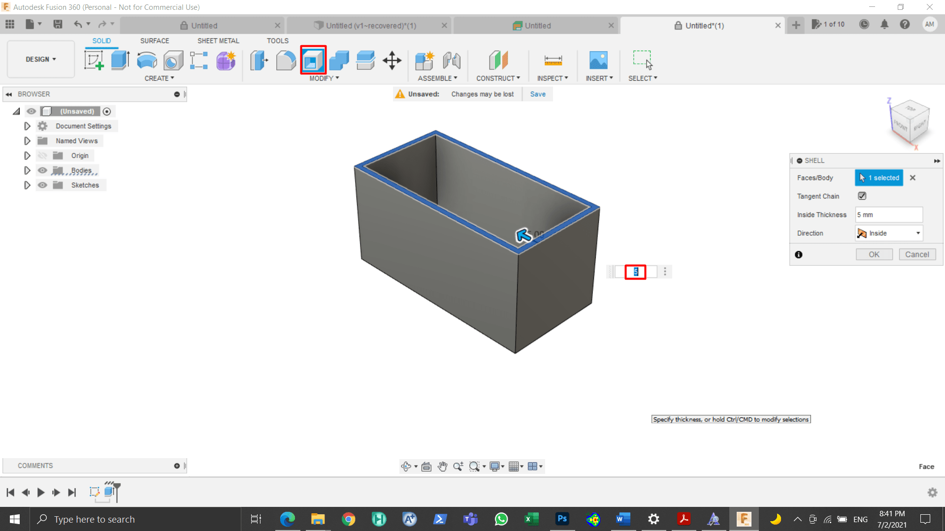
Figure 22: Utilizing the “Shell” function
Finally, the 3D design was made as shown in Fig. (23).
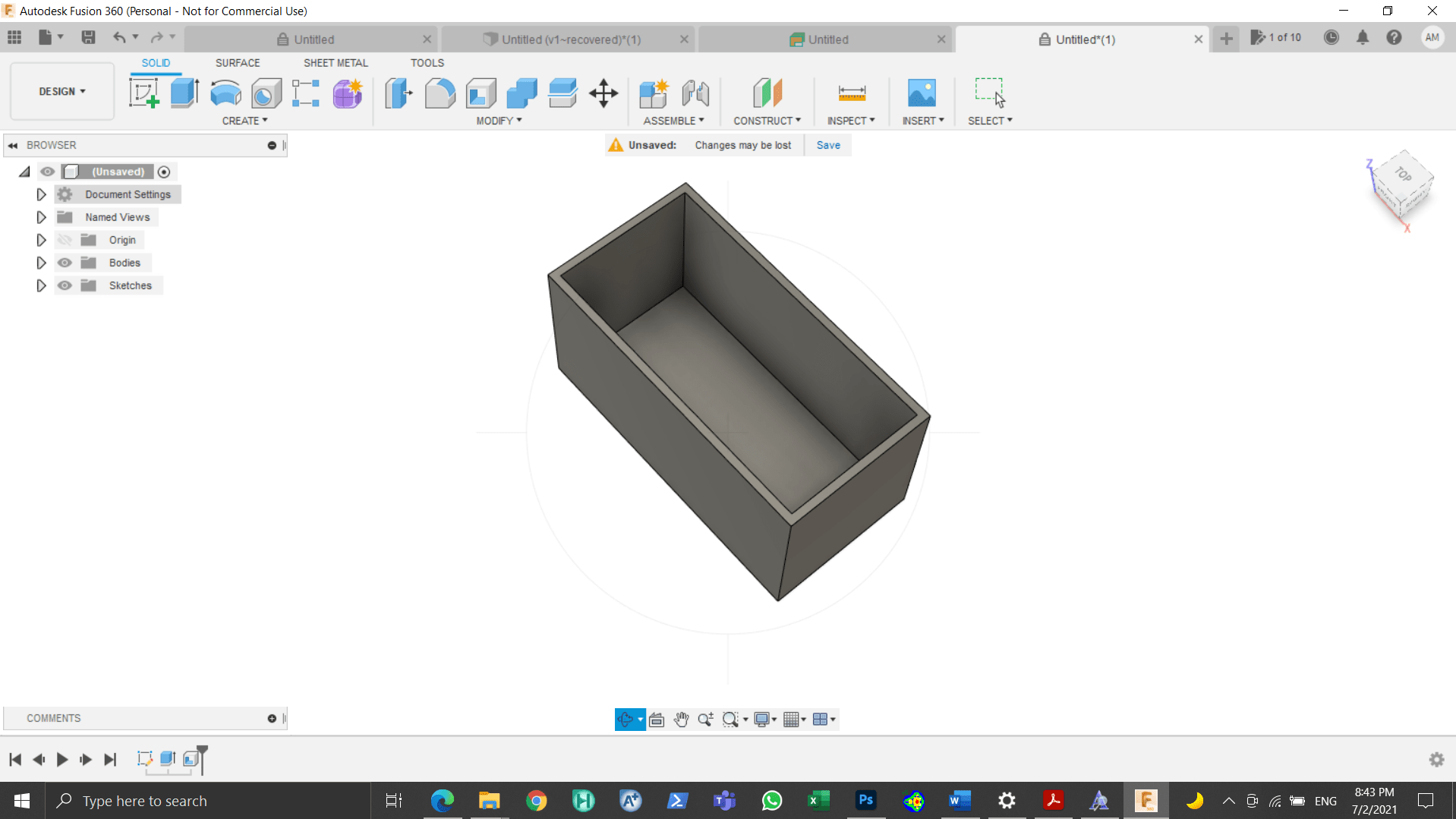
Figure 23: Final 3D design
Openscad
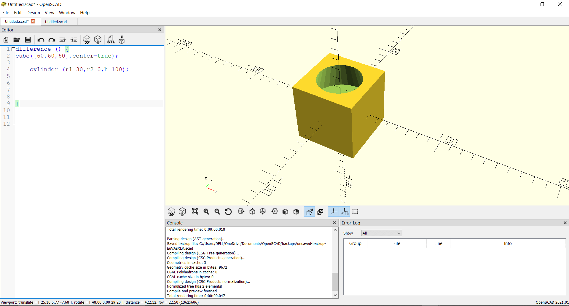
Openscad is a free software application for creating solid 3D designs. It is a script-only based software that utilizes its own description language. The 3D design can be viewed in the software but cannot be changed unless you change the code written [4].
A cube was made with the following dimensions (i.e., 60, 60, 60) and it was put in the center using (center=true) command. Then, a cylinder was made with the following dimensions (r1=30, r2=0, h=100). The cube and the cylinder have intersected at the middle, so when the difference function is utilized there will be an opening in the middle. The final design is showcased in Fig. (24).