5. Large format CNC
This week’s task was to cut a 3D design which was made in Fusion 360 software through using the CNC (Computer Numerical Control) machine. Computer Numerical Control is a technology that is utilized for automated control of machining tools such as drills through usage of computers. A CNC machine drills though a piece of material to meet specifications by following a coded programmed instruction and without a manual operator directly controlling the machine [1].
Fusion 360 Design
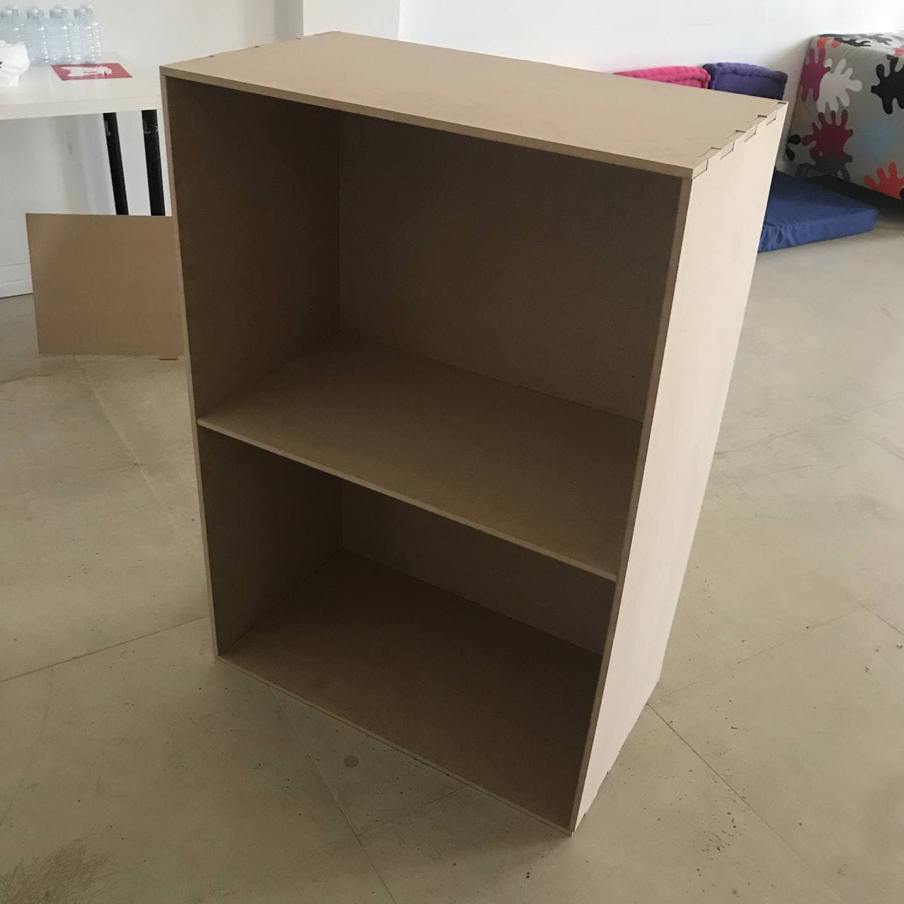
Firstly, a sketch was done and a rectangle was made, as shown in Fig. (1).
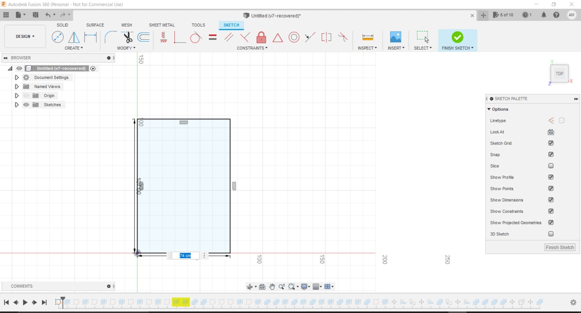
Figure 1: Sketching a rectangle
Then this rectangle was extruded as shown in Fig. (2).

Figure 2: Extruding the rectangle
Similarly, the other faces of the box were sketched and extruded and combined upon utilizing the combine tool as shown in Fig. (3).
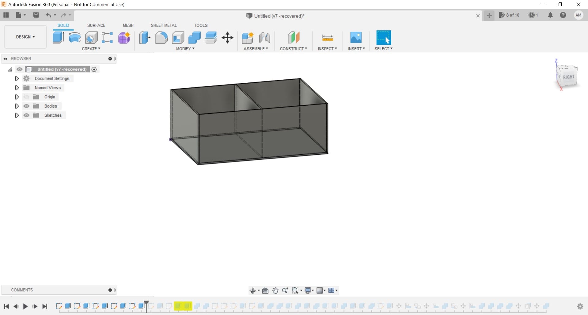
Figure 3: Implementing similar procedure and combining all faces of the box
The joints then were added on one side of the box as shown in Fig. (4).
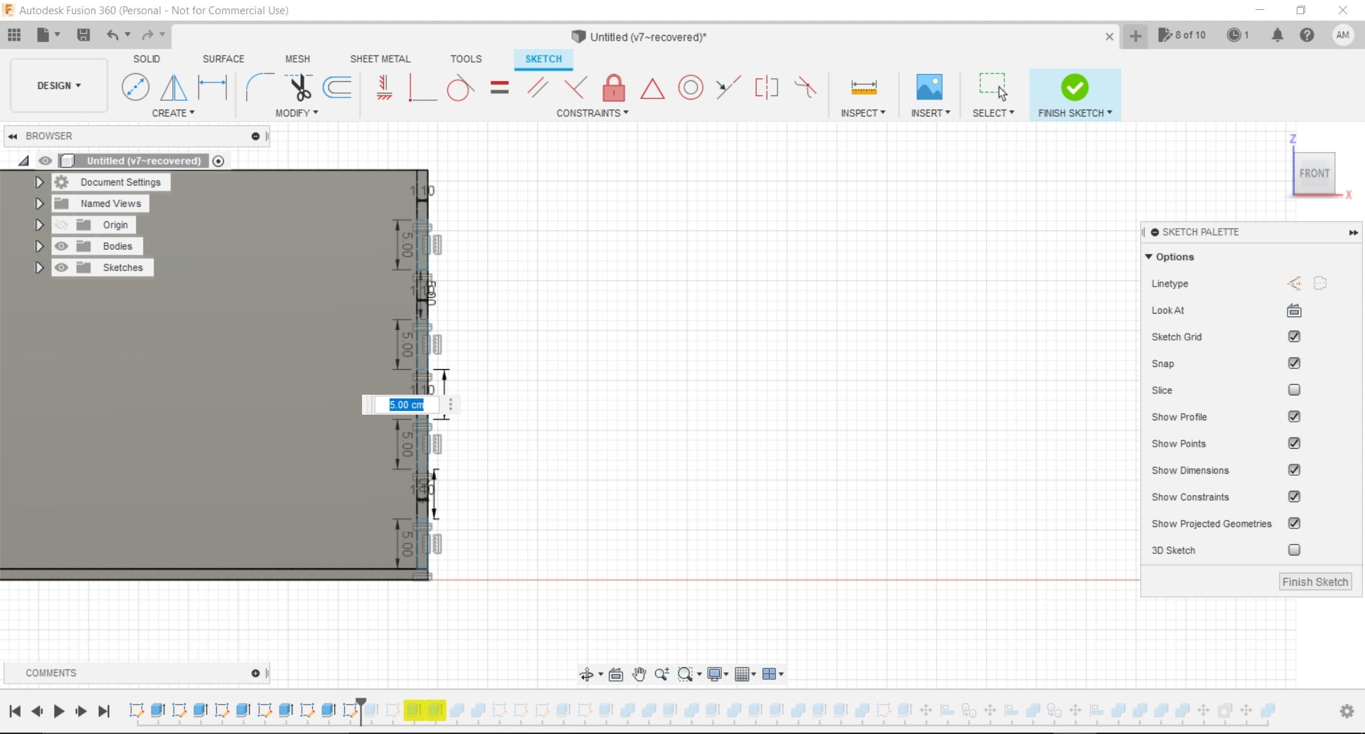
Figure 4: Sketching the joints
Figure 5 showcases how the joints looked on the design after the “FINISH SKETCH” option was chosen.
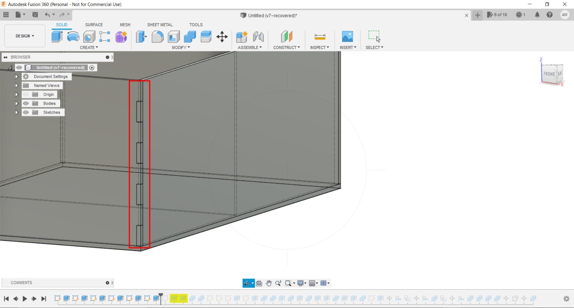
Figure 5: After pressing “FINISH SKETCH” option
Similarly, the joints were added for the other sides of the box as shown in Fig. (6).

Figure 6: Adding joints to all other sides of the box
It is noteworthy that all the dimensions were kept above 75 cm except for the thickness which was 11 mm, since the sheet that was utilized had a thickness of 11 mm. This was done in order to make use of the CNC machine, which can cut up to a length of 2.4 m and a width of 1.2 m, which cannot be done in a laser cutter, since the laser cutter cannot cut above 70 cm. The design tolerance for the joints was kept as 0.137 mm based on literature and also it was the most convenient, since going above 0.137 mm will make the joint loose and easy to remove, while going above 0.137 mm will make it hard for the joint to bind with the other materials because its too tight [2]. Each face of the box was then exported alone as a DXF file and sent to the laptop connected to the CNC machine.
Safety
The CNC machines is one of the most dangerous devices in Fablab, so it was necessary to take safety into consideration.
In case anything goes wrong there are different methodologies to stop the CNC machine, either by pressing the emergency button on the CNC machine or the emergency button on the control panel or by pressing any button on the laptop which will pause the progress of the machine. The aforementioned emergency tools are showcased in Fig. (7), Fig. (8) and Fig. (9), respectively.
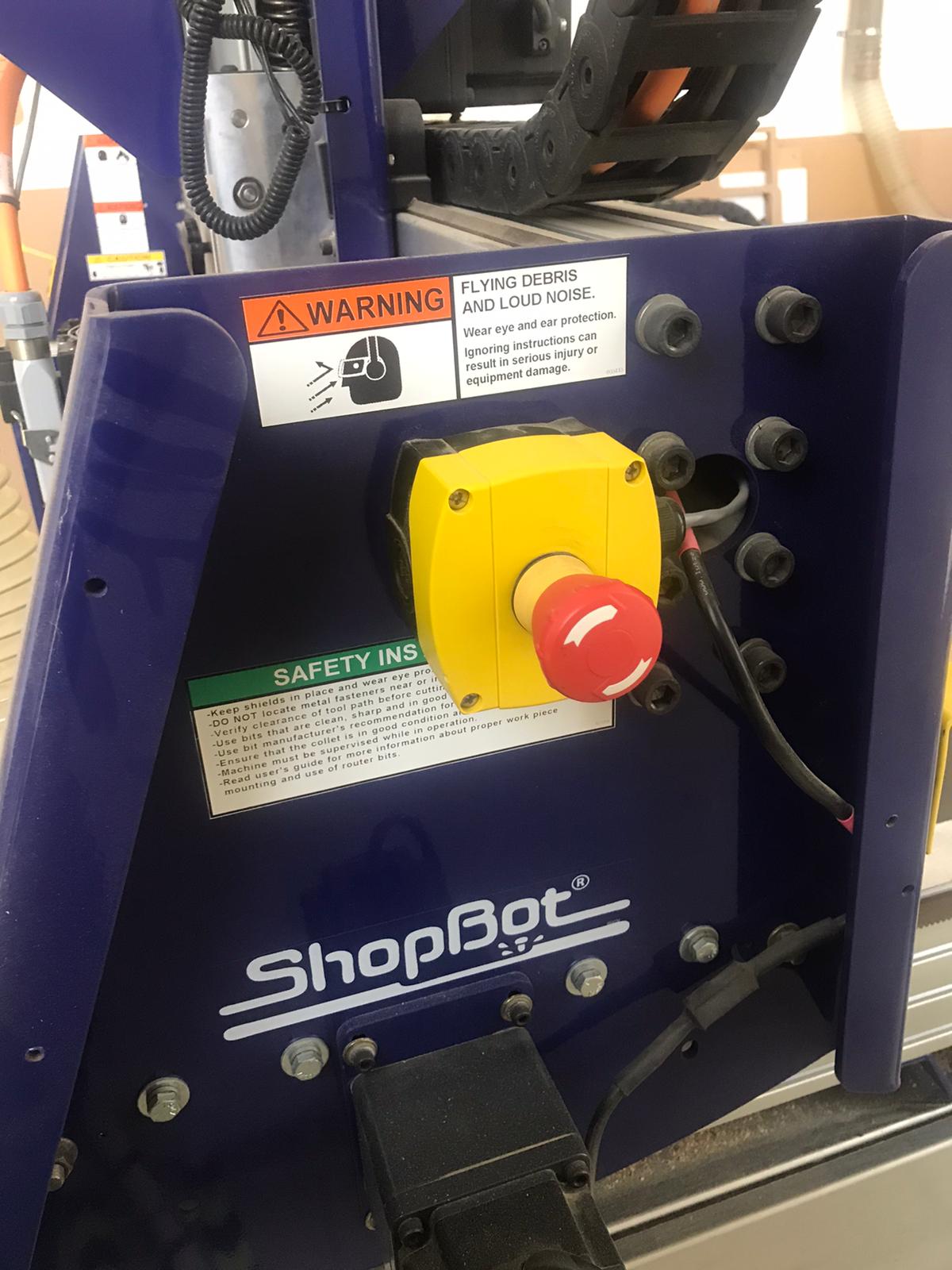
Figure 7: Emergency button on the CNC machines
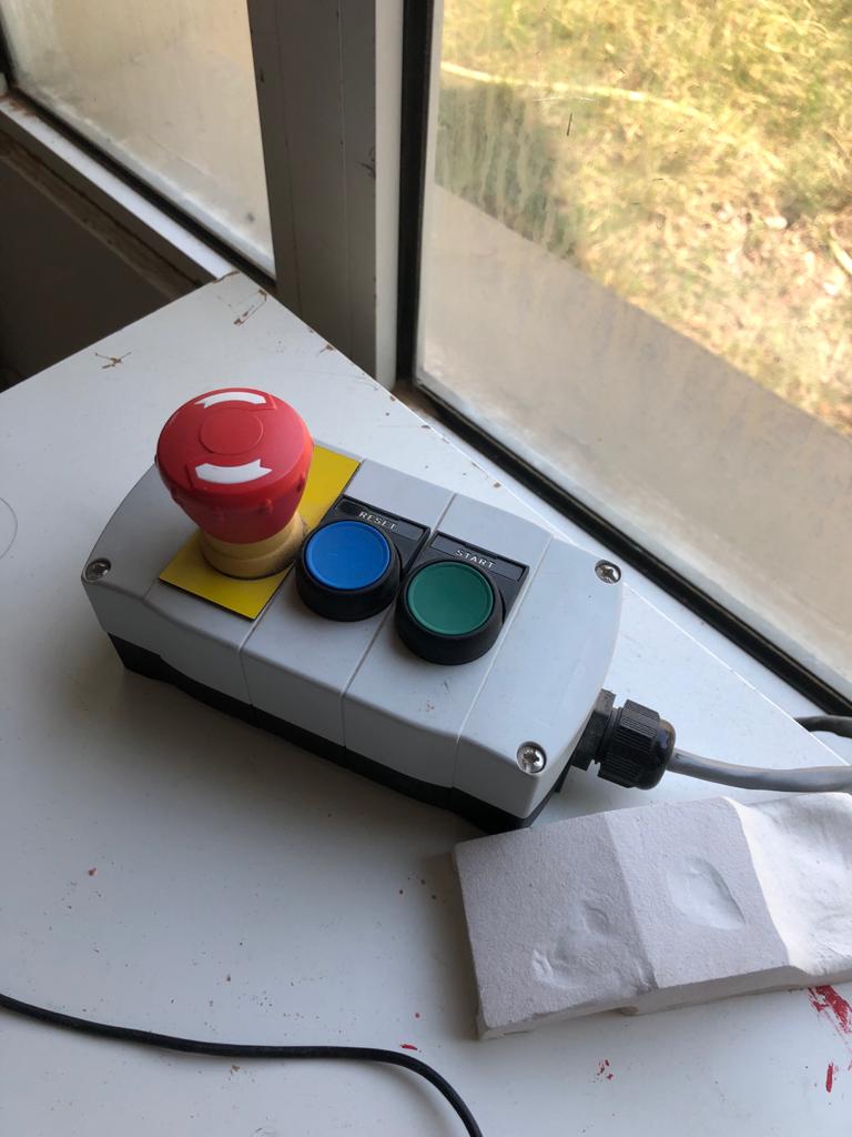
Figure 8: Emergency button on the control panel
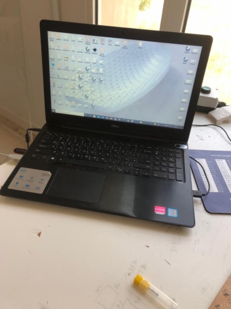
Figure 9: Laptop connected to the CNC machine
On the other hand, an extra sheet called the sacrifice was mounted below the MDF (Medium Density Fiberboard) sheet where the design was performed,
because design flaws can occur at anytime and some extra space will be drilled and will go through the MDF sheet and will damage the machine if there was no sacrifice sheet. Figure 10 showcases the black sacrifice sheet which is below the MDF sheets.
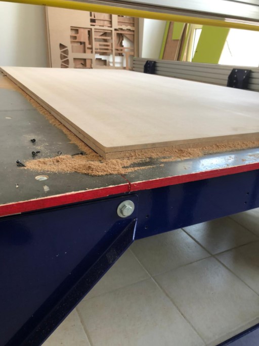
Figure 10: Sacrifice sheet
Moreover, during the cutting process, sawdust was produced and was eliminated through the usage of the cleaning machine shown in Fig. (11) to avoid its accumalation and keep the place clean.
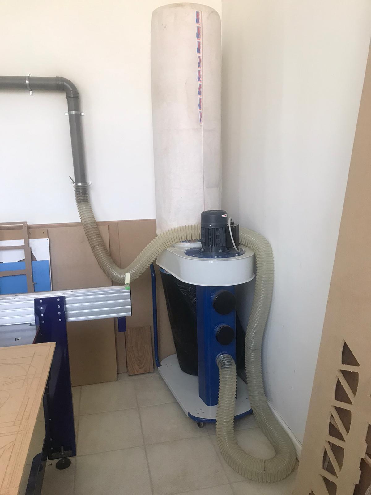
Figure 11: Cleaning machine
VCARVE: Why use it?
The CNC machine does not understand the 3D design that was done in Fusion 360, so this program was utilized as a translator for the CNC machine to understand the design.
Figure 12 shows the interface of the VCARVE program and the length, width and thickness were set as 1220, 2440 and 11 mm respectively and these were the dimensions of the MDF sheet.
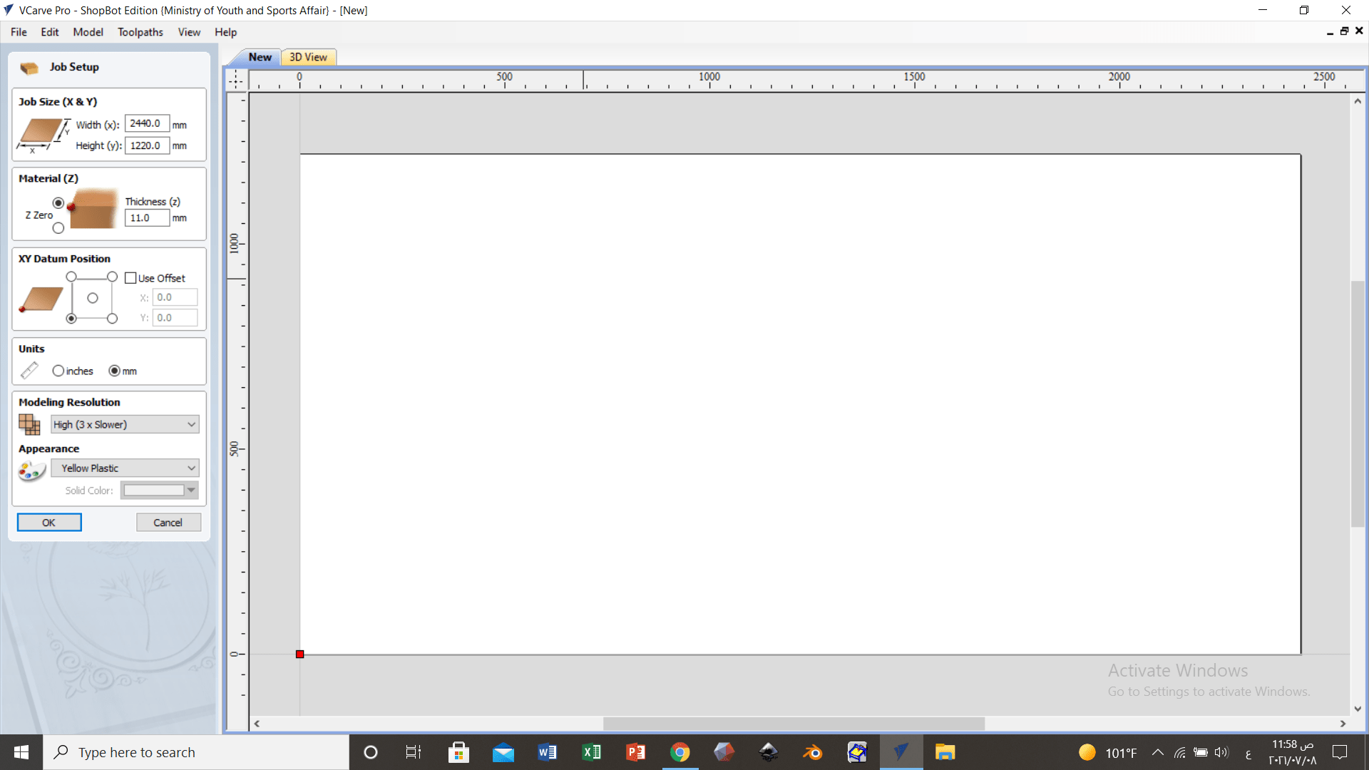
Figure 12: VCARVE program interface
An offset was created as a safety precaution such that the drilling will always be inside the sheet and the drillbit does not drill outside and damage the machine. This is showcased in Fig. (13).
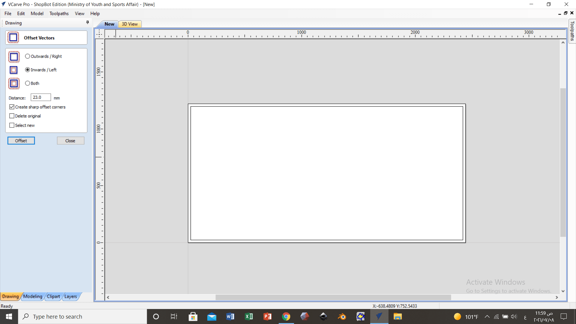
Figure 13: Creating an offset
The files were successfully imported into the software and then the joint vector command was utilized to keep the parts together as shown in Fig. (14).
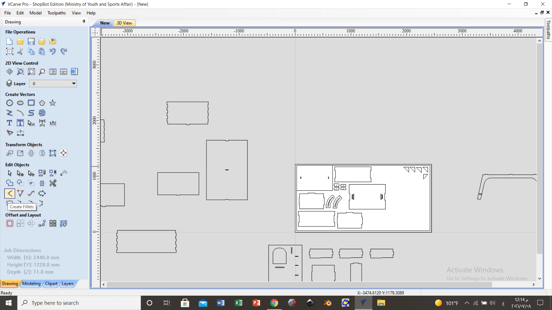
Figure 14: Joint vector command
Then a “T Bone” was added to make sure that the CNC machine cuts the edges well because there is a limitation in the CNC machine that does not cut the edges well unless a “T Bone” is added. This is showcased in Fig. (15).
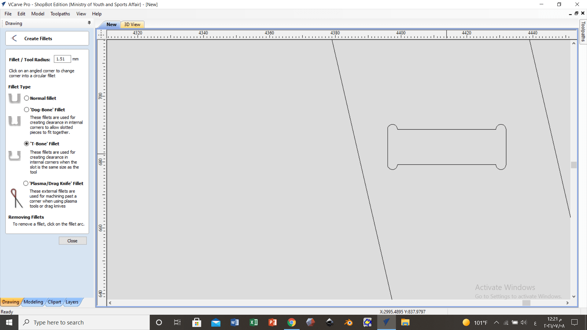
Figure 15: Adding a “T Bone”
The “Auto Nesting” command was utilized in an effort to automatically reassemble the designs in the best possible manner in the white area as shown in Fig. (16).
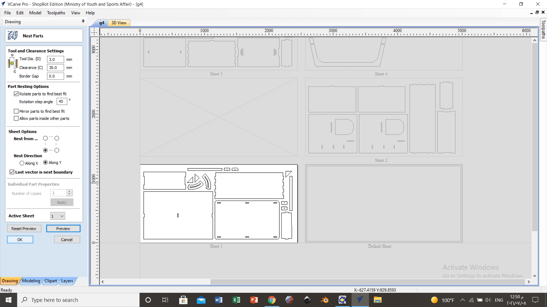
Figure 16: “Auto Nesting” command
After “profile tool paths” option was selected, the drillbit settings were changed in a effort to see how the design will look in the simulation before cutting. This is showcased in Fig. (17).
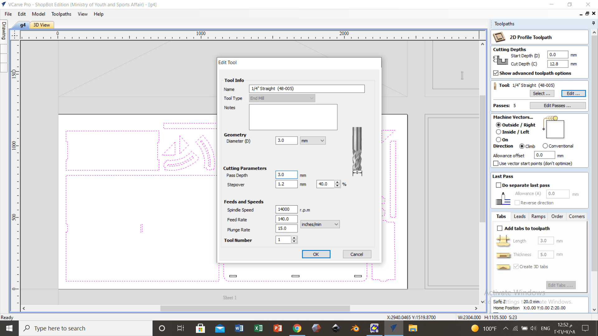
Figure 17: Adjusting the drill bit settings
The depth of cut and the number of passes were specified as shown in Fig. (18). The cutting processes has went through more than one pass because the drill bit might break if the cutting was done in one pass due to the large amount of force that the drillbit will exert in one pass.
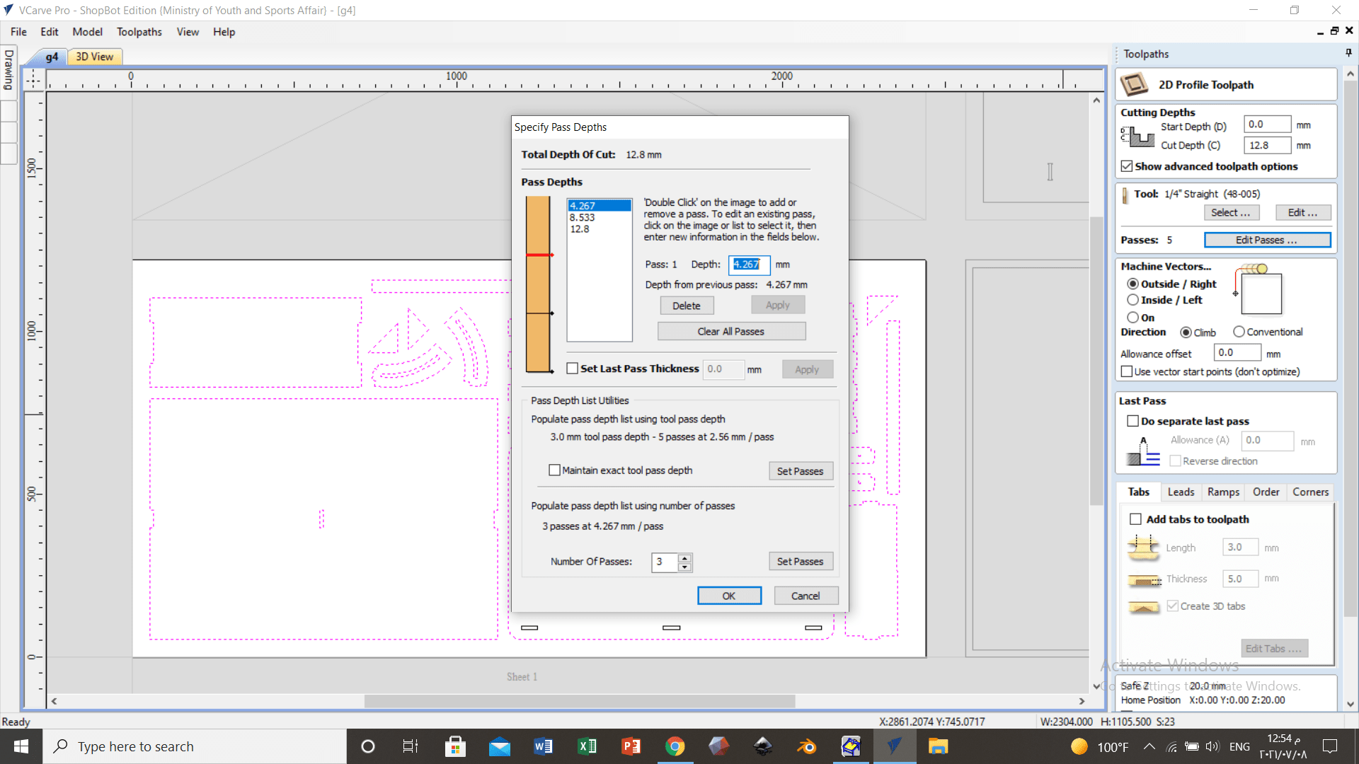
Figure 18: Adjusting the depths and number passes
Then taps were added to ensure more precise cutting as shown in Fig. (19).
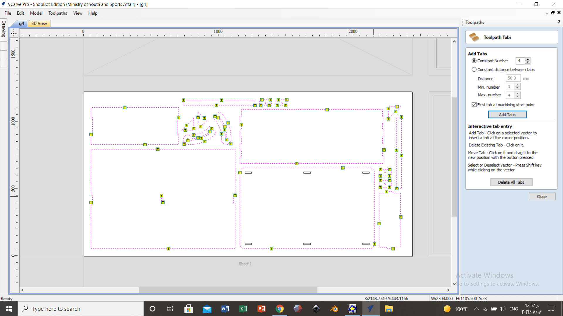
Figure 19: Adding taps
The thickness of cutting was made more than the material thickness in order to make sure that the drill bit goes through the material and into the sacrifice sheet, to ensure that the MDF sheet was completely drilled. The warning appearing in Fig. (20) was a notification about this issue.
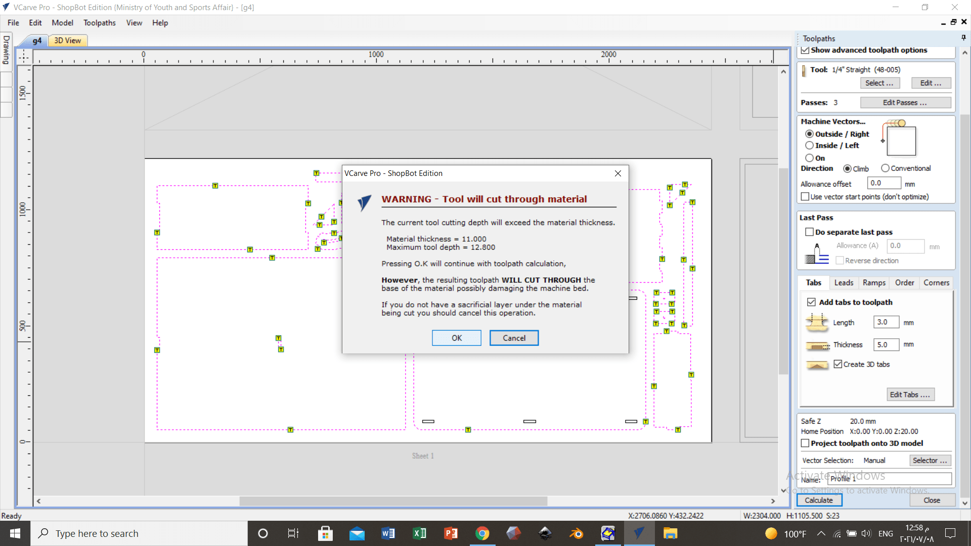
Figure 20: “Tool will cut through material” warning
Figure 21 showcases the control panel for the CNC machine, where the X, Y and Z axis dimensions were set and it also was utilized to move the bit in the intended direction.
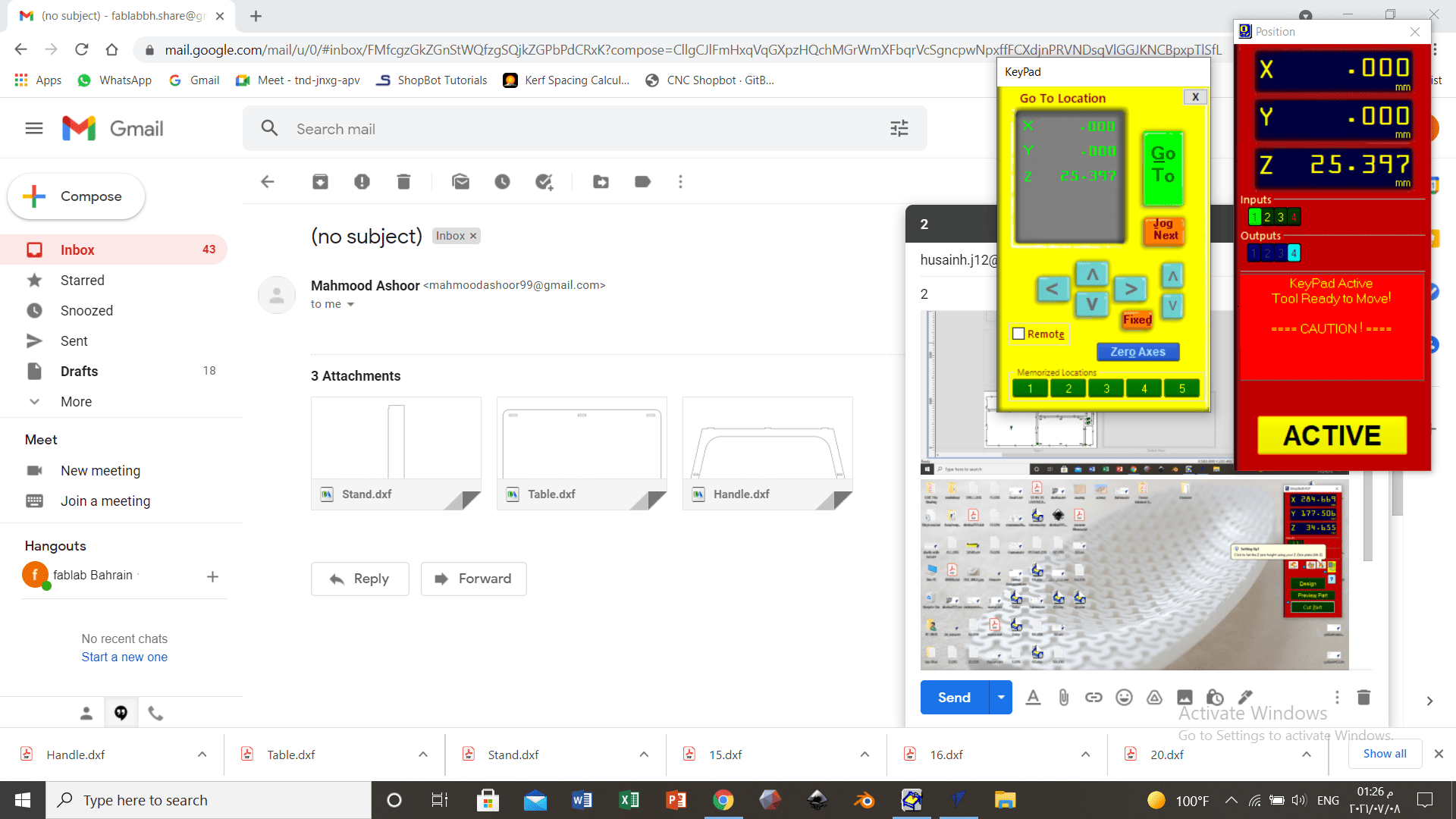
Figure 21: CNC machine control panel
Before the cutting process has started, the notification shown in Fig. (22) has appeared.
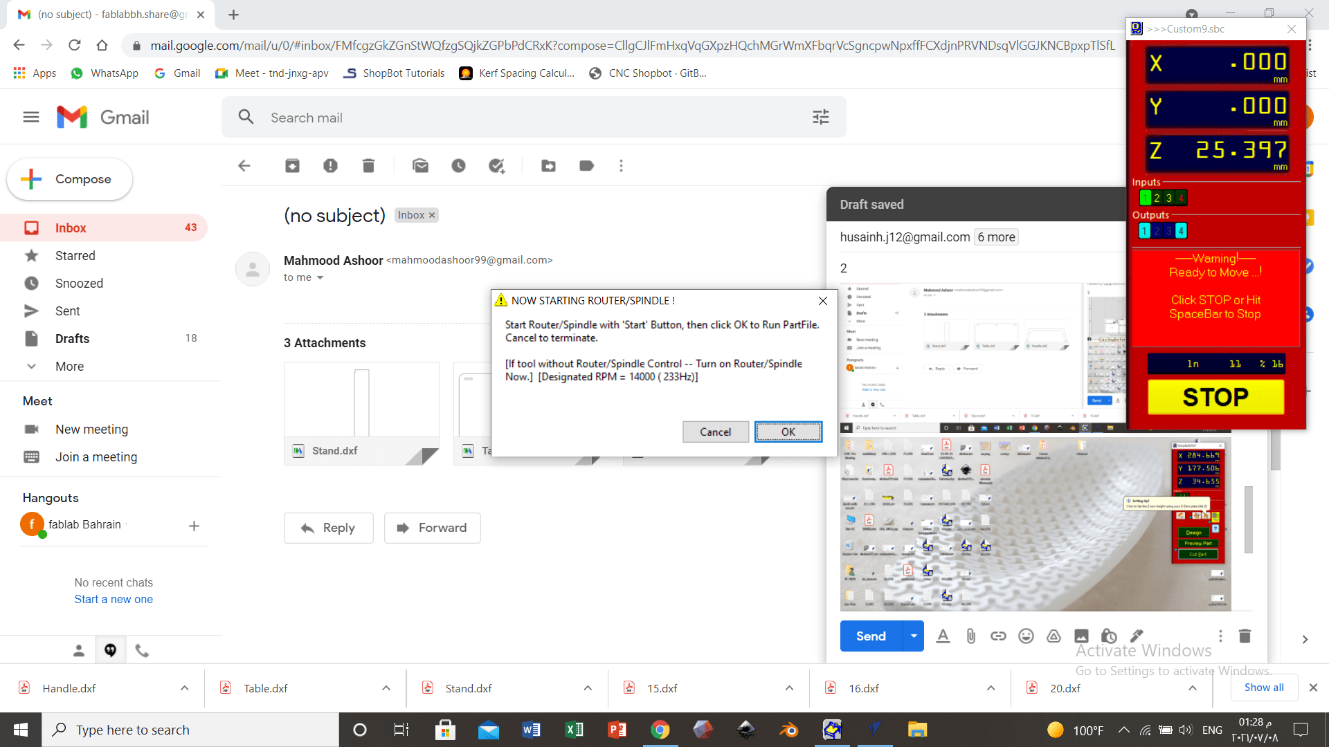
Figure 22: CNC machine notification
After Cutting
After cutting, the design was assembled. Figure 23 showcases the assembling process of the final product.
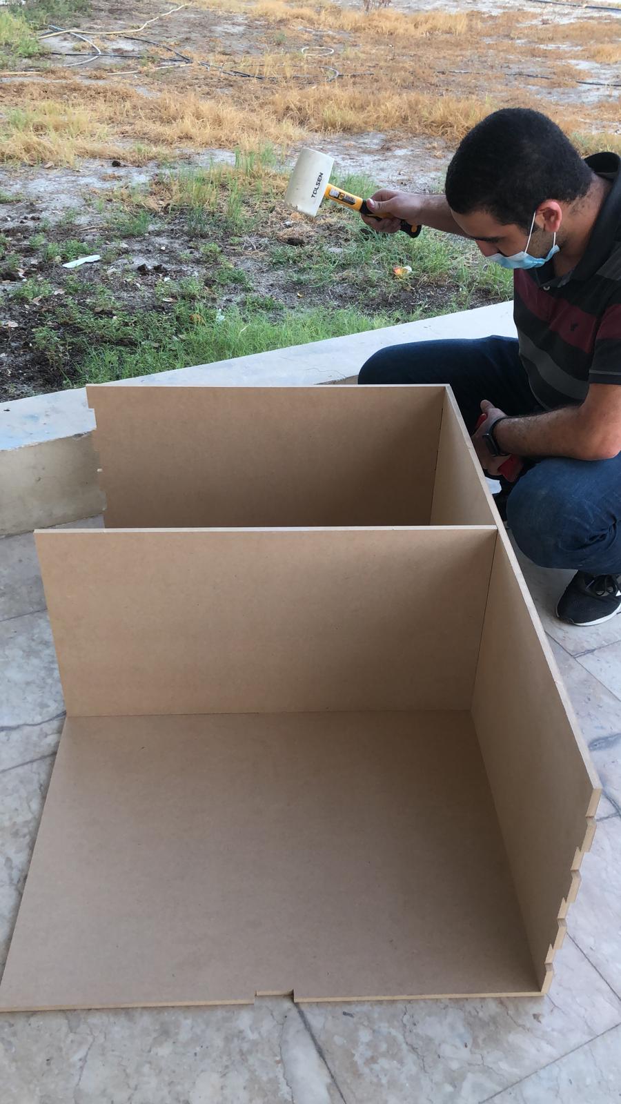
Figure 23: Assembling the final product
Final product
Figures 24 and 25 showcase the final product after assembling.
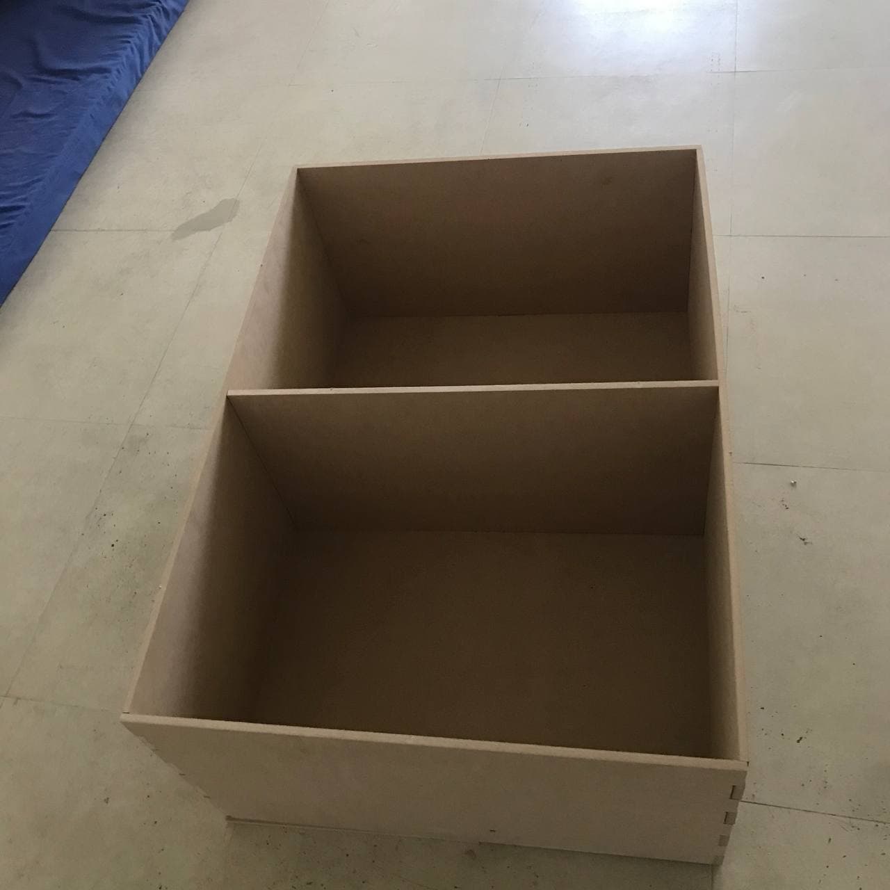
Figure 24: Final product mounted horizontally