3. Computer Controlled Cutting
This week task was to use the laser and vinyl cutter technologies in an effort to cut 2D designs.
Laser Cutting
Laser cutting is a fabrication technology that utilizes a thin laser beam to cut and etch materials into custom designs specified by a designer [1]. The design that will be cut using the laser cutter will be the lewis structure of Ethane (C2H6).
Performing Parametric Design
Firstly, Fusion 360 was opened and some parameters that will be used later in the design are set. This is showcased in Fig. (1) and Fig. (2).
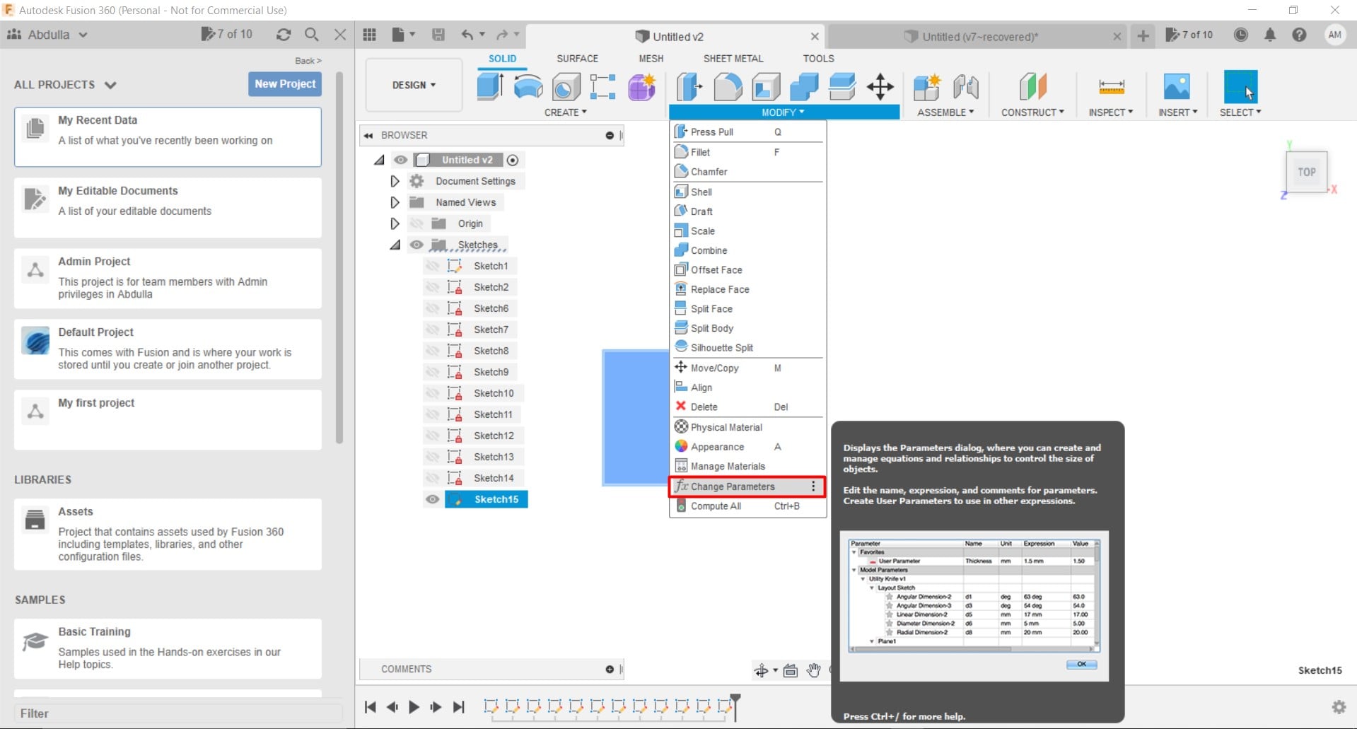
Figure 1: Opening the “Change Parameters” panel.
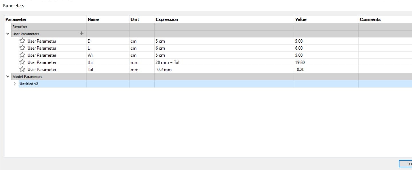
Figure 2: Setting the parameters that will be used later in the design
Fusion Design
Firstly, a circle was drawn as shown in Fig. (3).
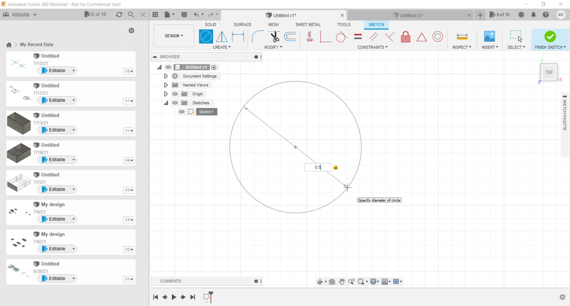
Figure 3: Drawing a circle
Then a triangle was placed on the inner core of the circle, as shown in Fig. (4).
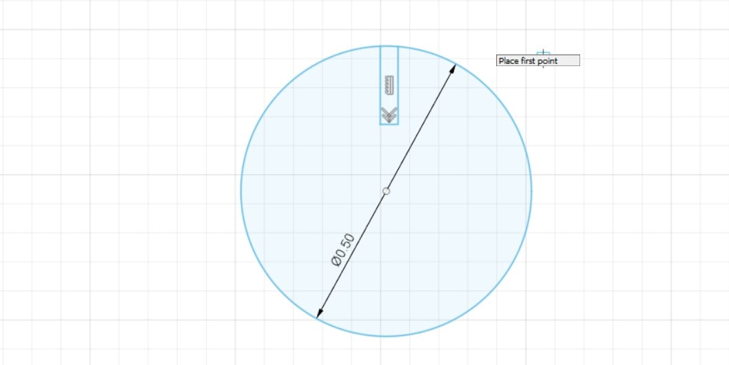
Figure 4: Placing a triangle on the inner core of the circle
Then the trim tool was selected and utilized to cut off this triangle, as shown in Fig. (5) and Fig. (6), respectively.
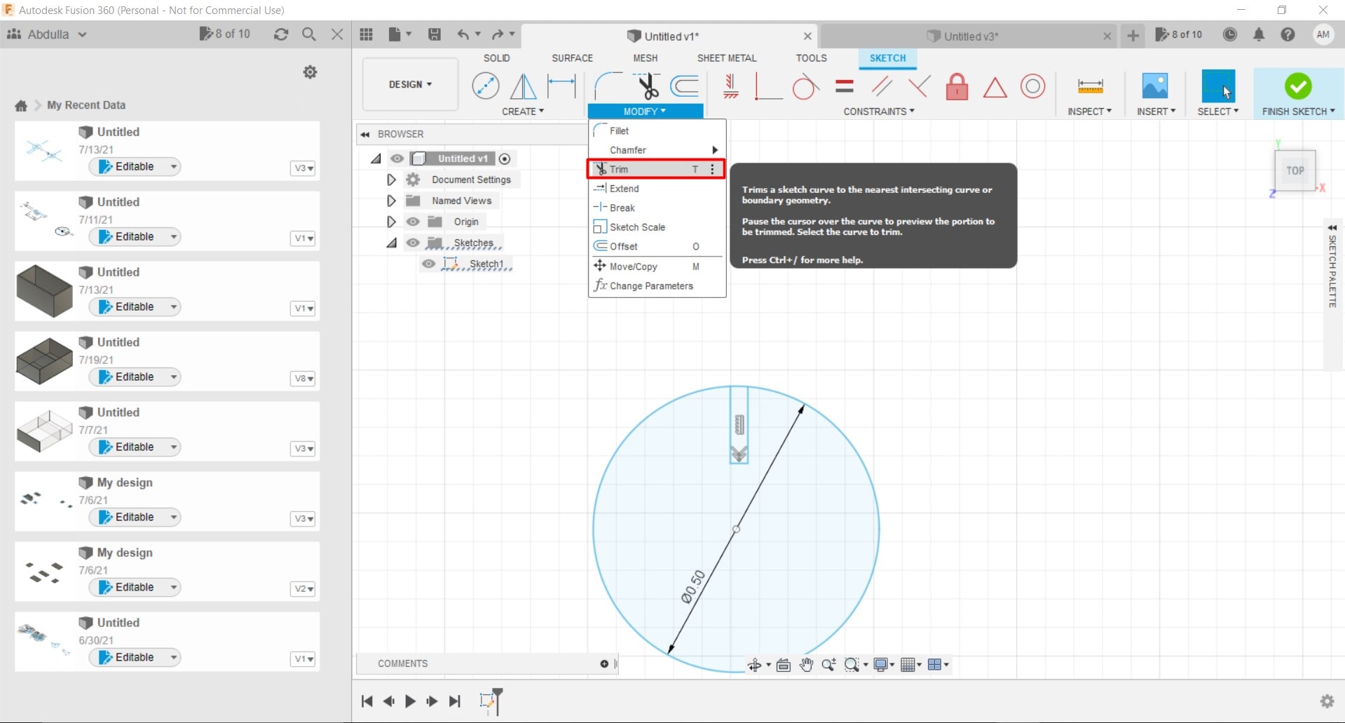
Figure 5: Selecting the trim tool
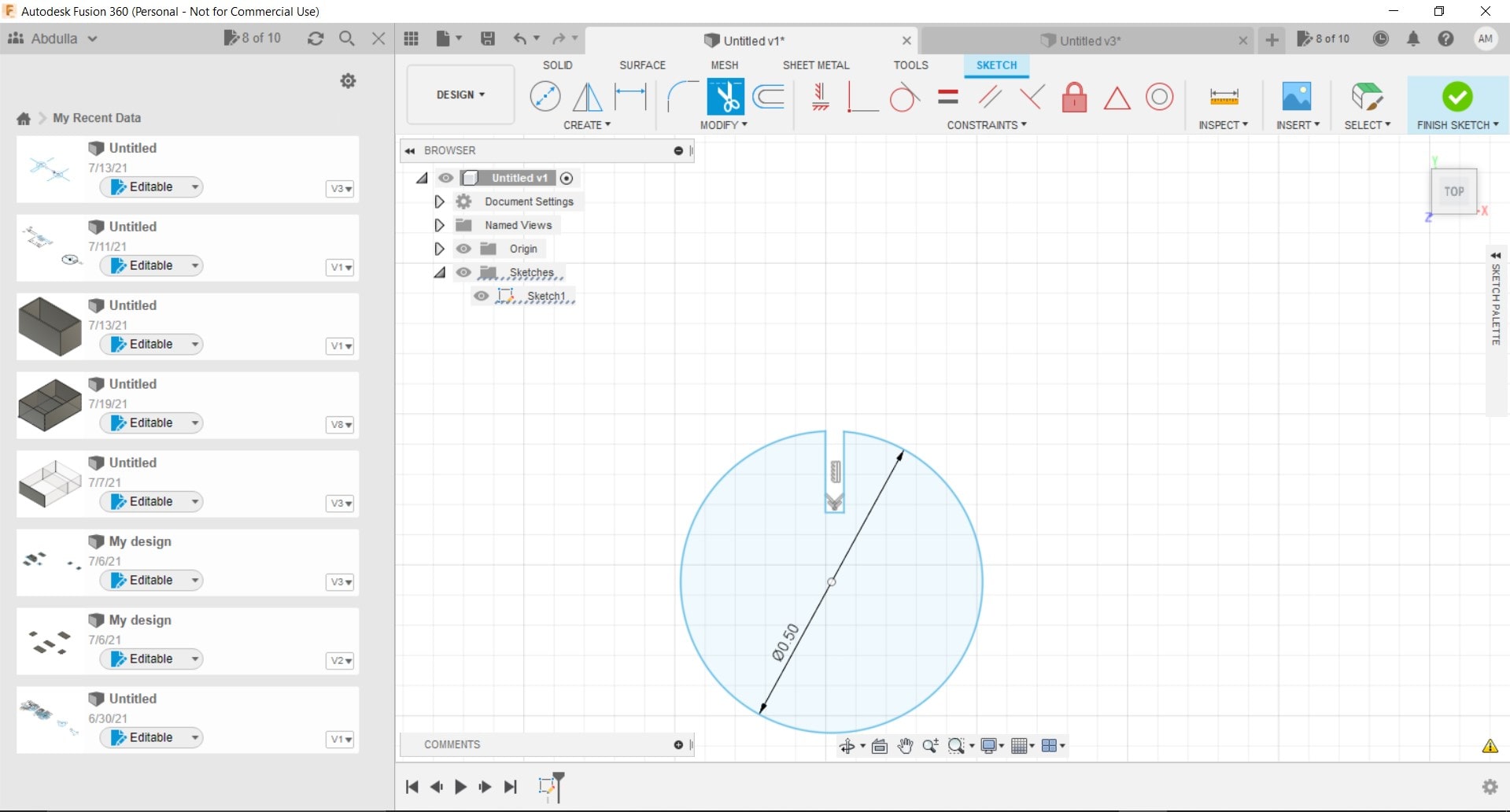
Figure 6: The triangle trimmed off from the circle
A similar procedure was implemented to all other sides of the circle, as shown in Fig. (7).
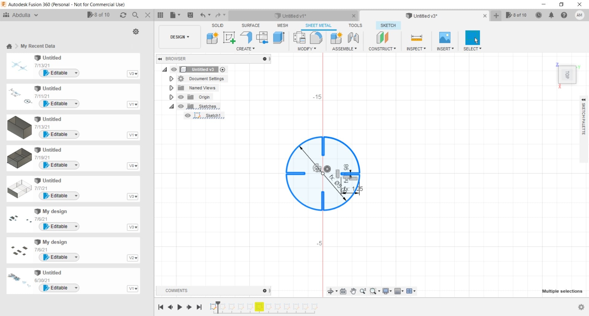
Figure 7: Triangles on all other sides of the circle trimmed off
Then a small triangle was drawn as shown in Fig. (8).

Figure 8: Small triangle drawn
Joint Test
This test was used to obtain the tolerance value that is most suitable for the design and it was found to be 1.15 mm.
Firstly, the design was imported to RDworks program which is the program that is utilized by the laser cutter. This is demonstrated in Fig. (9).
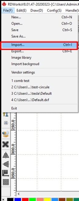
Figure 9: The design imported to RDworks
Then the parameters were adjusted in the “Layer Parameter” panel as shown in Fig. (10).
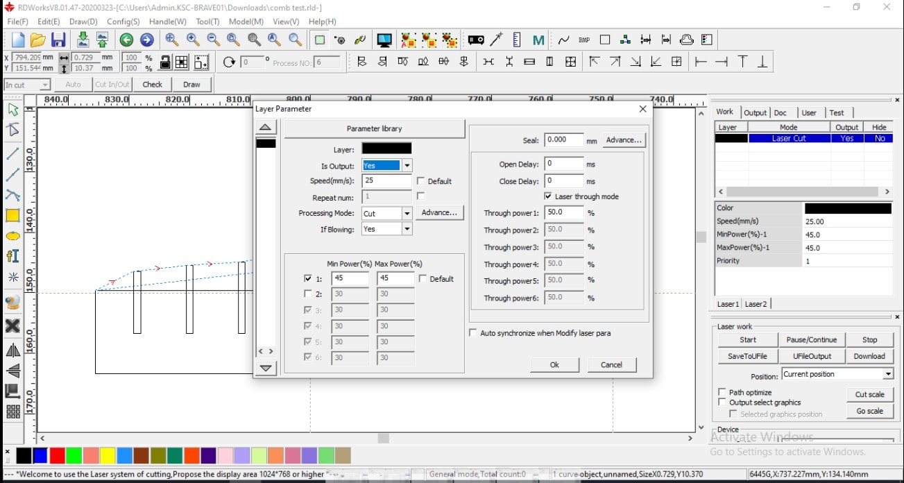
Figure 10: “Layer Parameter” panel
The following settings shown in the “Parametric library” panel were the cutting settings for each type of material, for example the cardboard had a thickness of 1.15 mm and similarly for other types of materials. The “Parametric library” panel is demonstrated in Fig. (11).
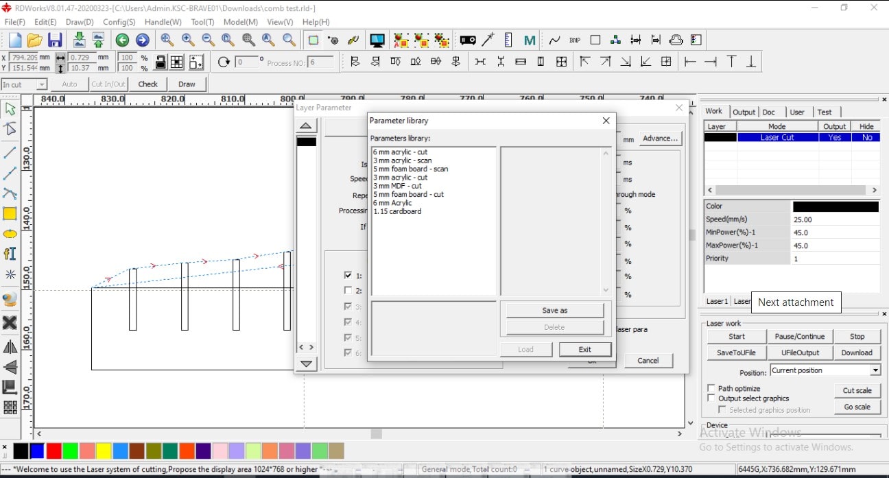
Figure 11: Parametric library panel
Then the document was named “12” and after the “ok” button was pressed, it was saved. This is shown in Fig. (12).
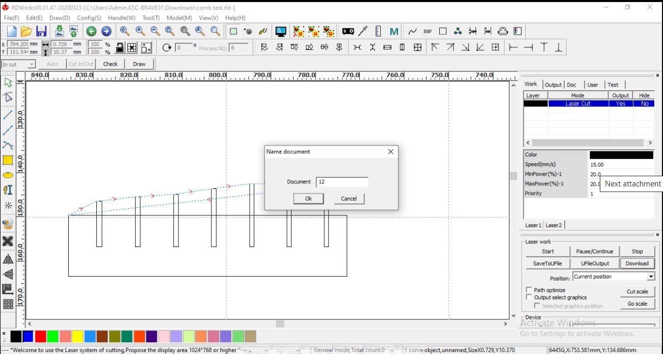
Figure 12: Document saving process
Then, the file was downloaded to the laser cutter as shown in Fig. (13).
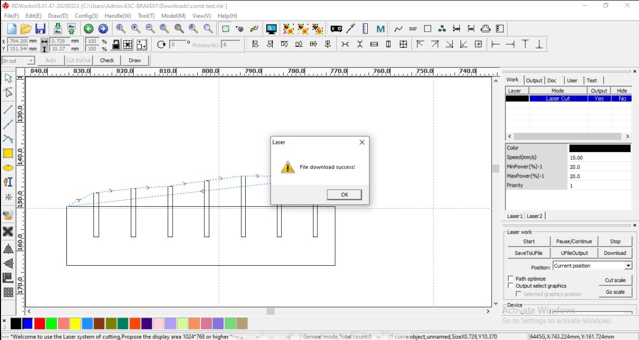
Figure 13: File downloaded to the laser cutter
The design was uploaded to the laser cutter after the buttons “File” and “Enter” were pressed. This is illustrated in Fig. (14).
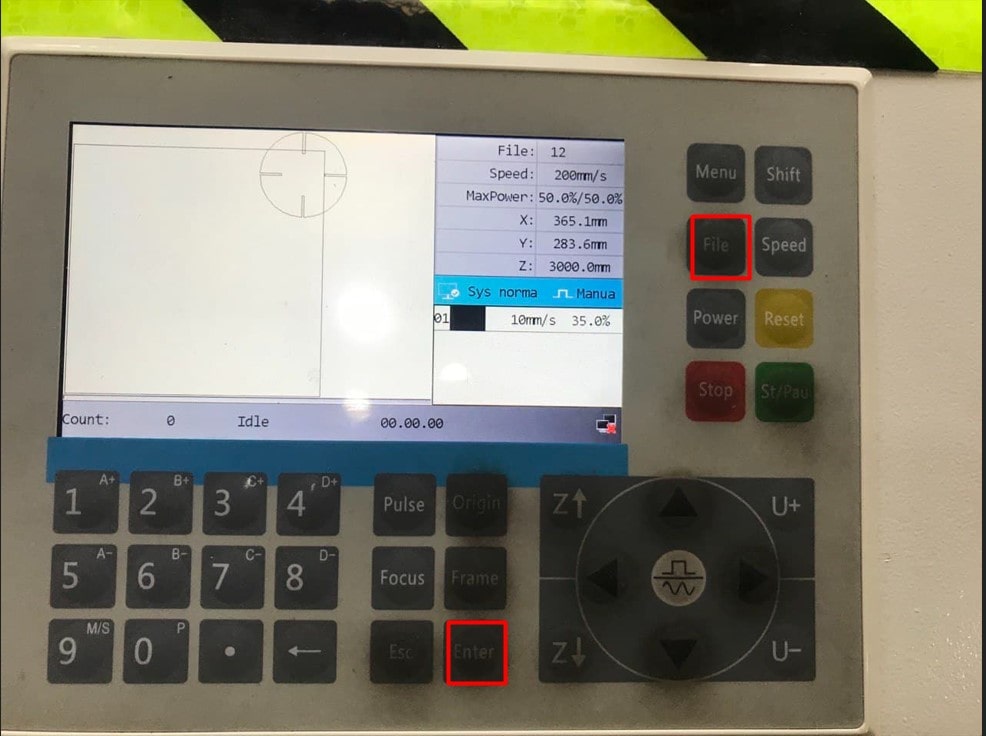
Figure 14: Procedure of uploading the design to laser cutter
Then the origin button was utilized to set the new origin and the “Frame” button was used to see how much space on the cardboard was needed during the cutting process and whether it will exceed the required space or not. This is shown in Fig. (15).
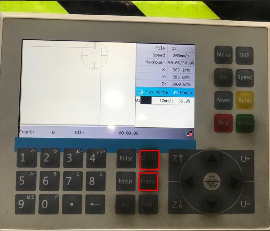
Figure 15: Setting a new origin and checking if their is enough space on the cardboard
Then the design was printed and assembled as shown in Fig. (16).
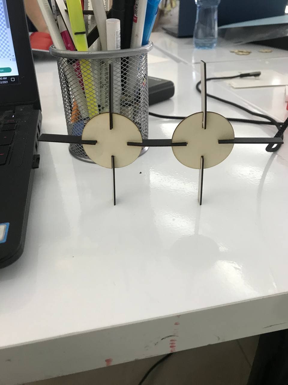
Figure 16: Final design assembled
Vinyl Cutting
It is a technology that is utilized to print some stickers, names etc.
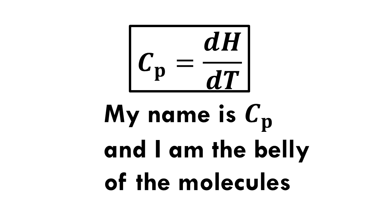
Firstly, the design was made in Microsoft PowerPoint as shown in Fig. (17).
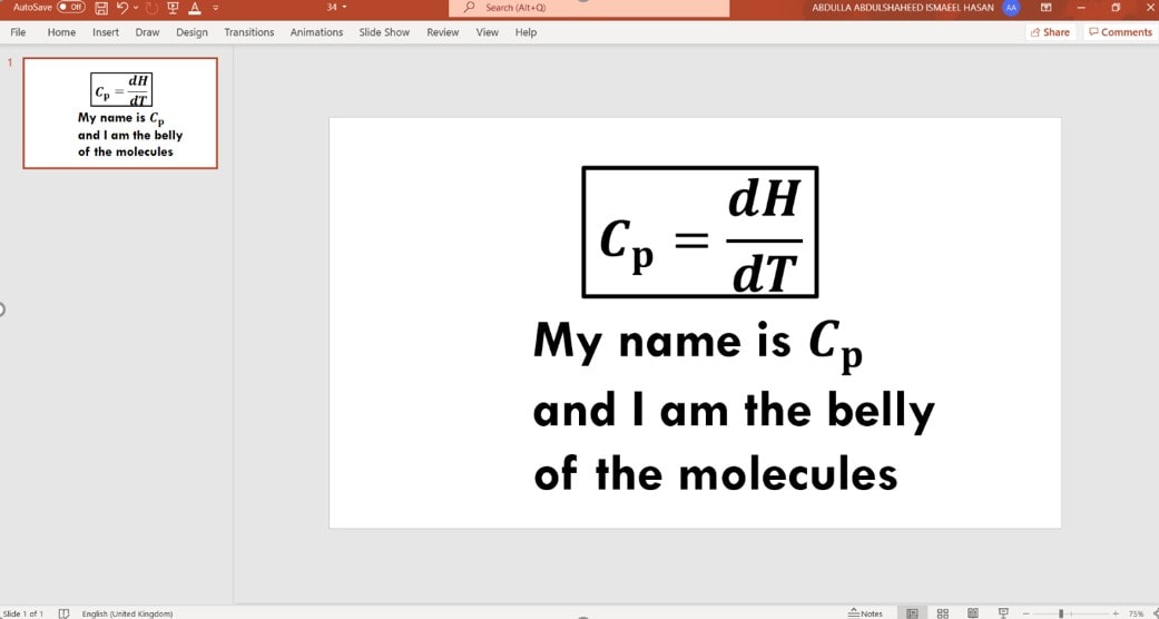
Figure 17: Design in Microsoft PowerPoint
Then the design was saved as a PNG.
The “Upload image” command in Cricut Design software was used to upload the image as shown in Fig. (18).
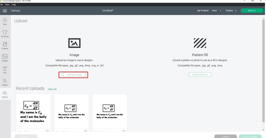
Figure 18: Upload image command
After the image was uploaded, the option complex was selected to get fine detail and blended colors. This is showcased in Fig. (19).
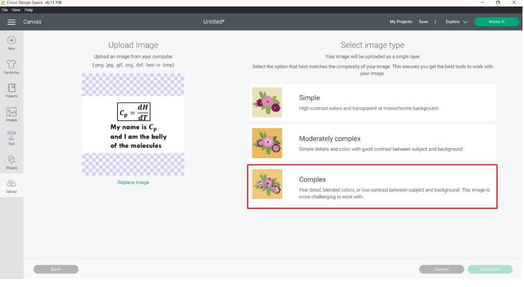
Figure 19: Complex option
Moreover, the image was selected and the continue button was pressed to proceed. This is showcased in Fig. (20).
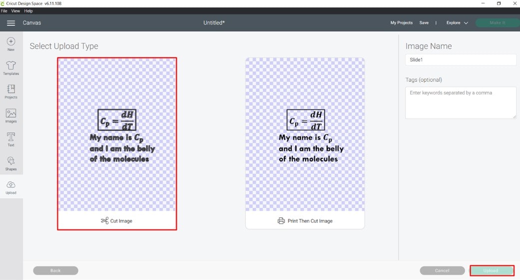
Figure 20: Selecting the image
The latest design was chosen as shown in Fig. (21).
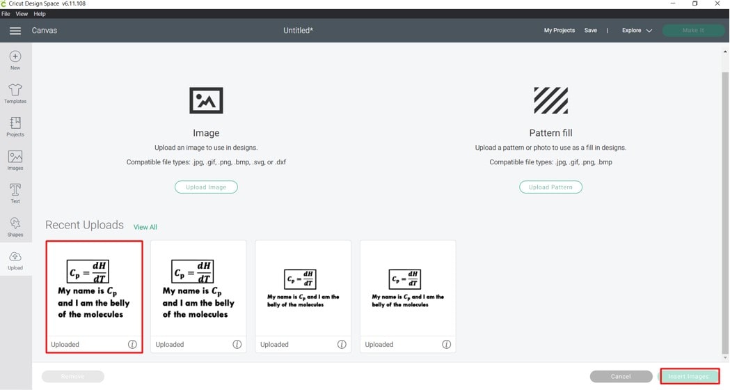
Figure 21: Choosing the latest design
The “Make it” option was pressed to make the design. This is shown in Fig. (22).
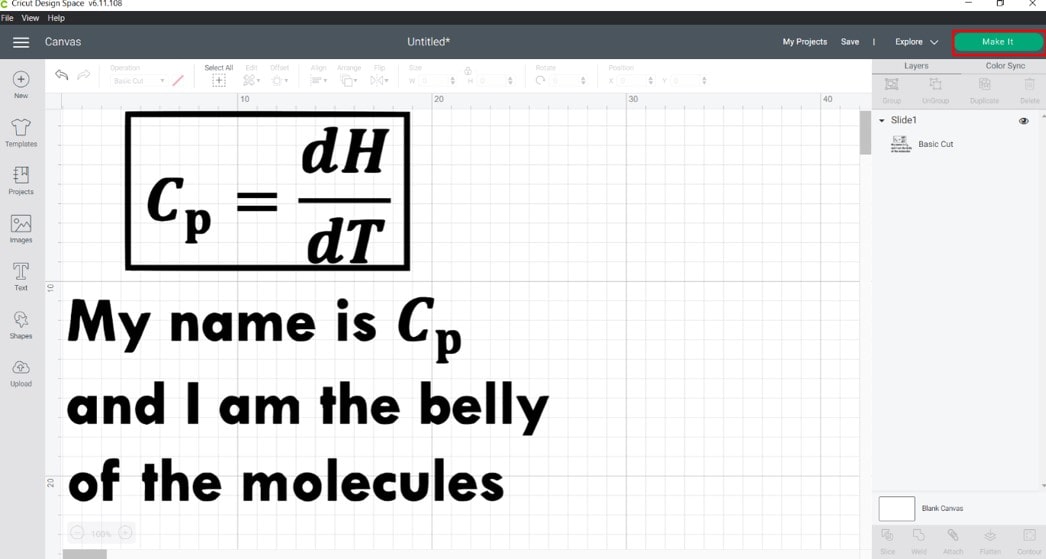
Figure 22: “Make it” option
Before printing the design the printing paper was inserted into the machine as shown in Fig. (23).
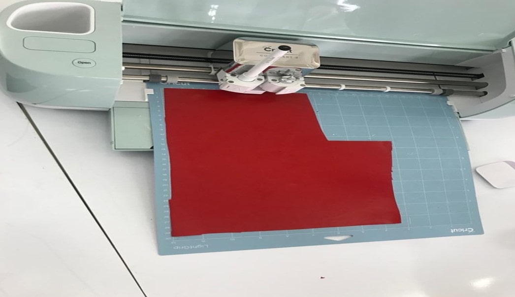
Figure 23: Inserting the paper into the machine
Then after printing, a process called weeding was implemented, which is removing the extra paper and just leaving the designed sticker that should be pasted on the designated place. This is showcased in Fig. (24).
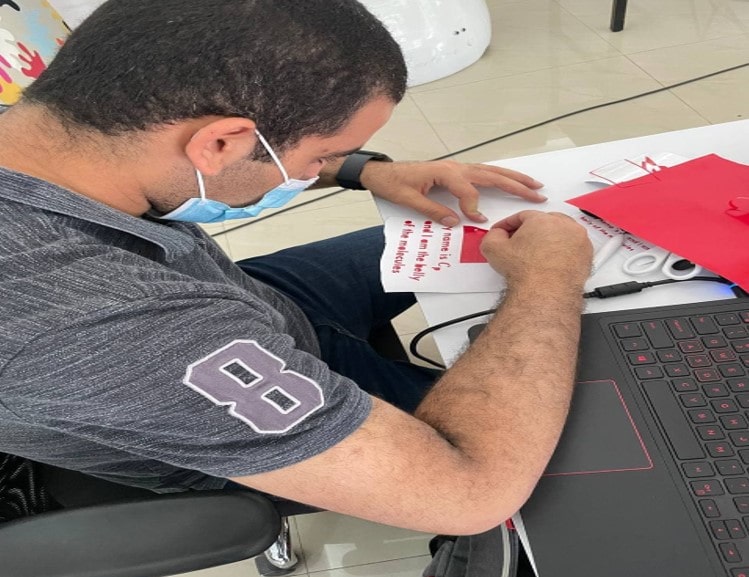
Figure 24: Implementing the weeding process
After weeding, a ribbon was utilized to stich the sticker on it. This is showcased in Fig. (25).
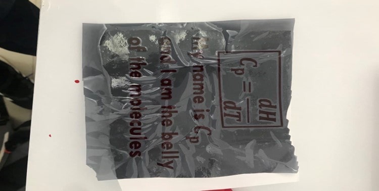
Figure 25: Transferring the sticker to the ribbon
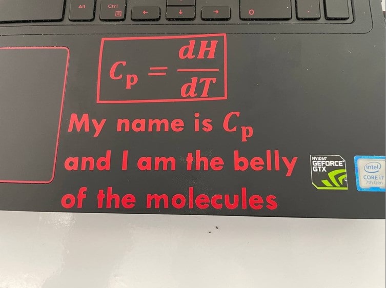
Then the sticker was transferred from the ribbon to the laptop as shown in Fig. (26).