7. Embedded programming
This weeks task encompassed working with a microcontroller. A microcontroller is a compact integrated circuit designed for a specific operation in an embedded system [1].
Arduino
The Arduino program was used to program the microcontroller. The Arduino program and drivers were downloaded from the internet [2, 3].
Arduino Nano
The Arduino Nano is a small, complete, and breadboard-friendly board based on the ATmega328 [4].
Figure 1 showcases the constituents of the board.
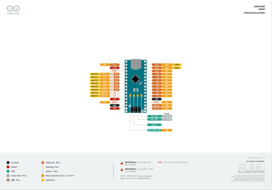
Figure 1: Constituents of the Arduino Nano board [5]
The following details are information about the ports of the board [5]: The ports D0-D13 are input/output ports.
A0-A7 are analog input channels.
PWR is the voltage supply.
3V3 is a 3.3V output.
Reset port is for resetting the device.
Then the microcontroller was connected to the computer as shown in Fig. (2).
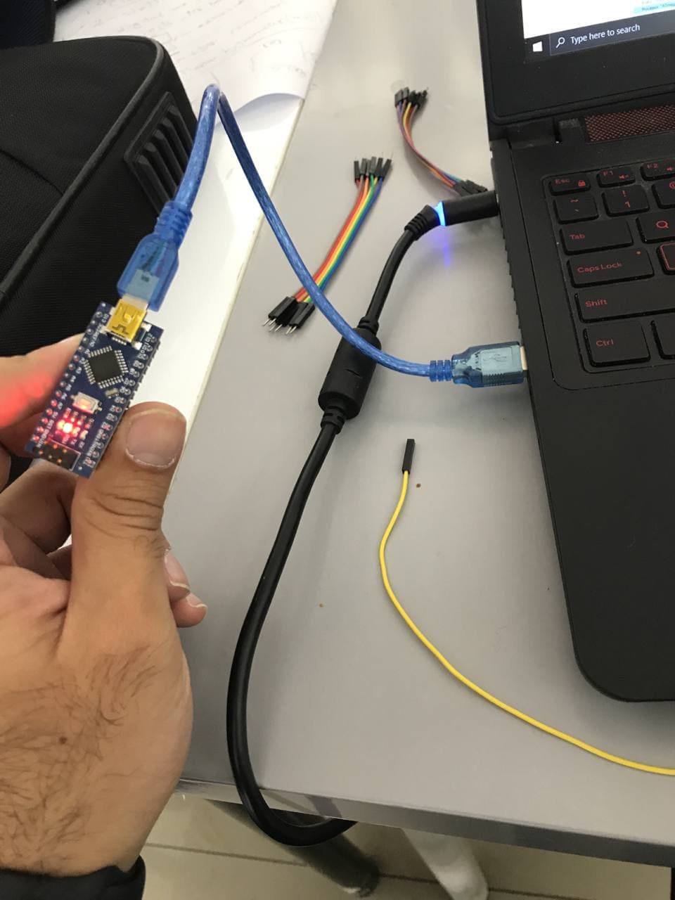
Figure 2: Microcontroller connected to the computer
Then the Arduino program was opened and the board was setted up through the following procedure:
The suitable board, processor and port were selected as shown in Fig. (3), Fig. (4) and Fig. (5), respectively.
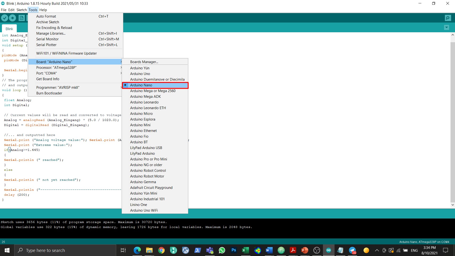
Figure 3: Choosing the board
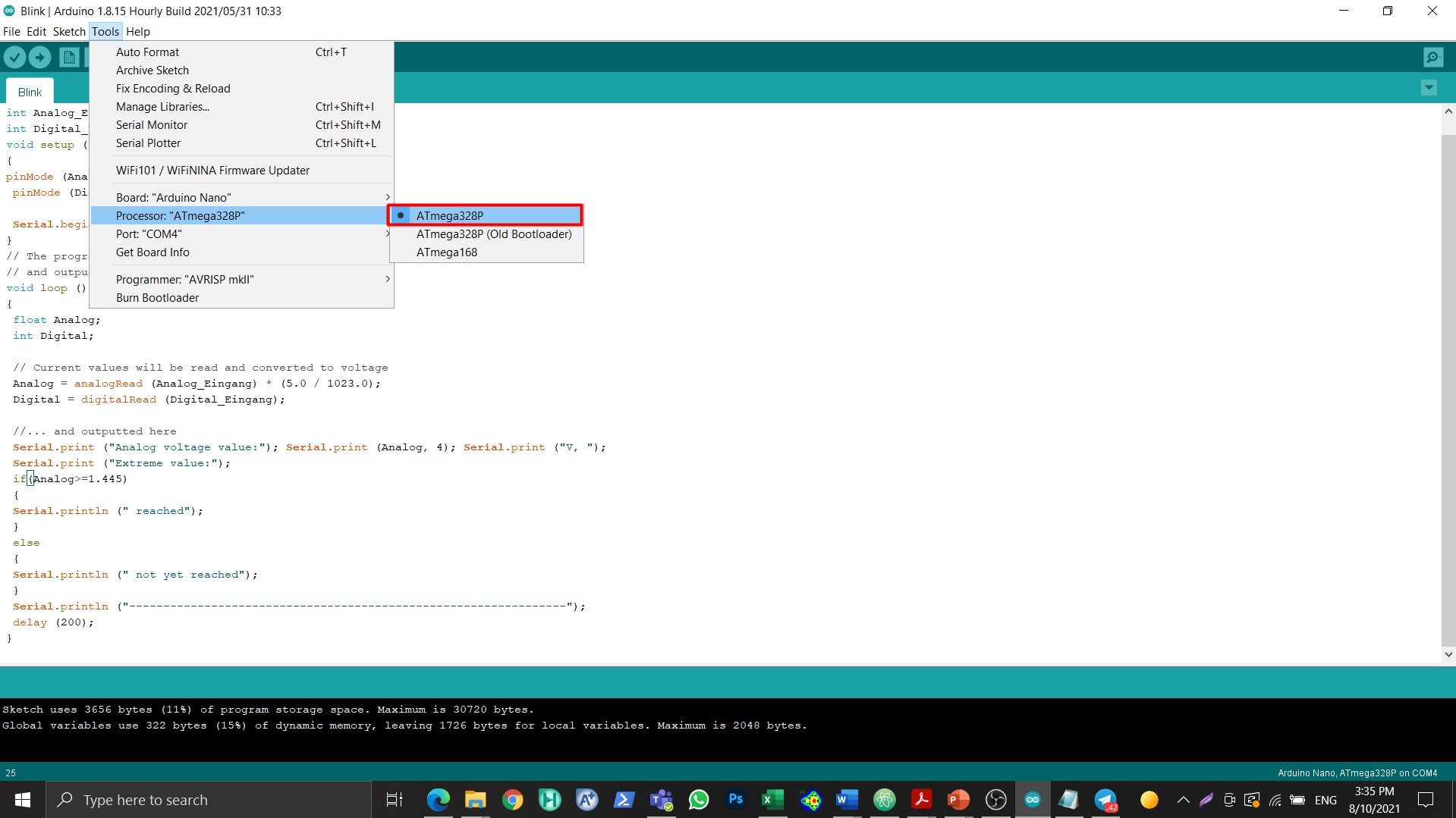
Figure 4: Choosing the processor
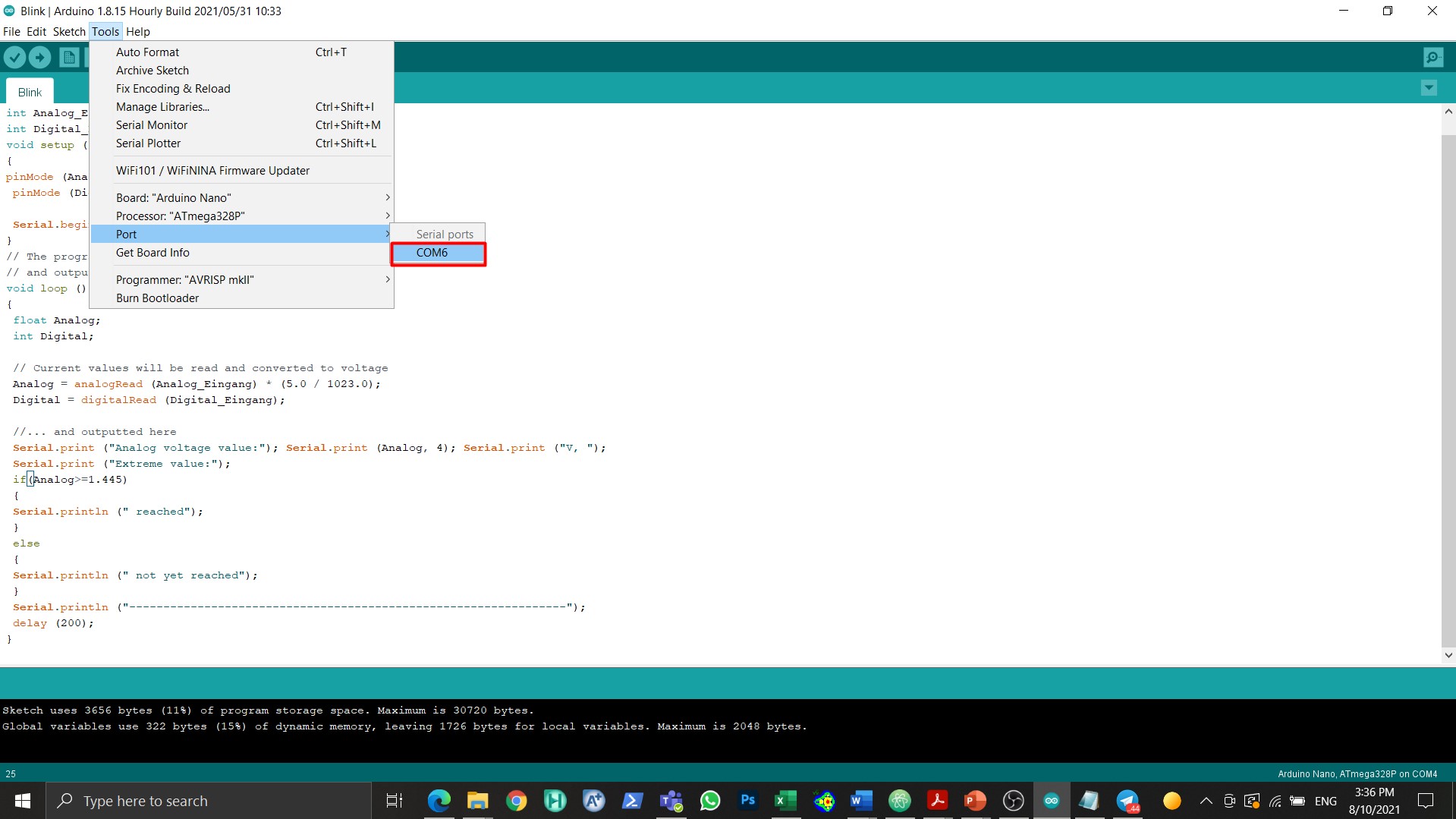
Figure 5: Choosing the port
After the microcontroller setup was done, the blinking code was entered as shown in Fig. (6).
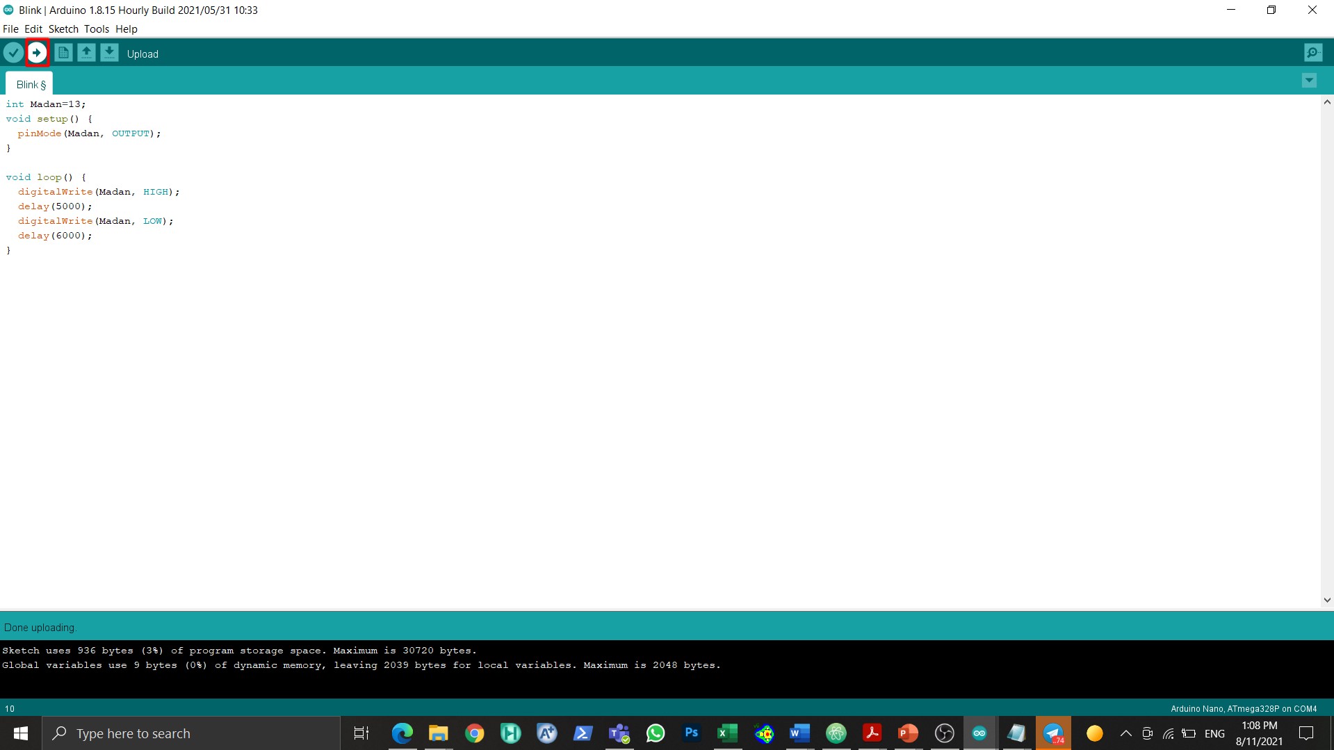
Figure 6: blinking code
The written blinking code is shown below
int Madan=13;
void setup() {
  pinMode(Madan, OUTPUT);
}

void loop() {
  digitalWrite(Madan, HIGH);
  delay(5000);
  digitalWrite(Madan, LOW);
  delay(6000);
}
The aforementioned was code based on the blinking example in Arduino. The code has been changed slightly and the time at which the light takes in order to turn on and off was changed to 6 and 5 seconds, respectively. When these changes were done, the light took longer time working on and off. Figure 7 showcases a GIF of the microcontroller after the code was applied.
Figure 7: GIF of the microcontroller
The second program that was utilized is called visual studio.
Visual studio was downloaded and installed [6].
The tab shown in Fig. (8) was opened in visual studio.
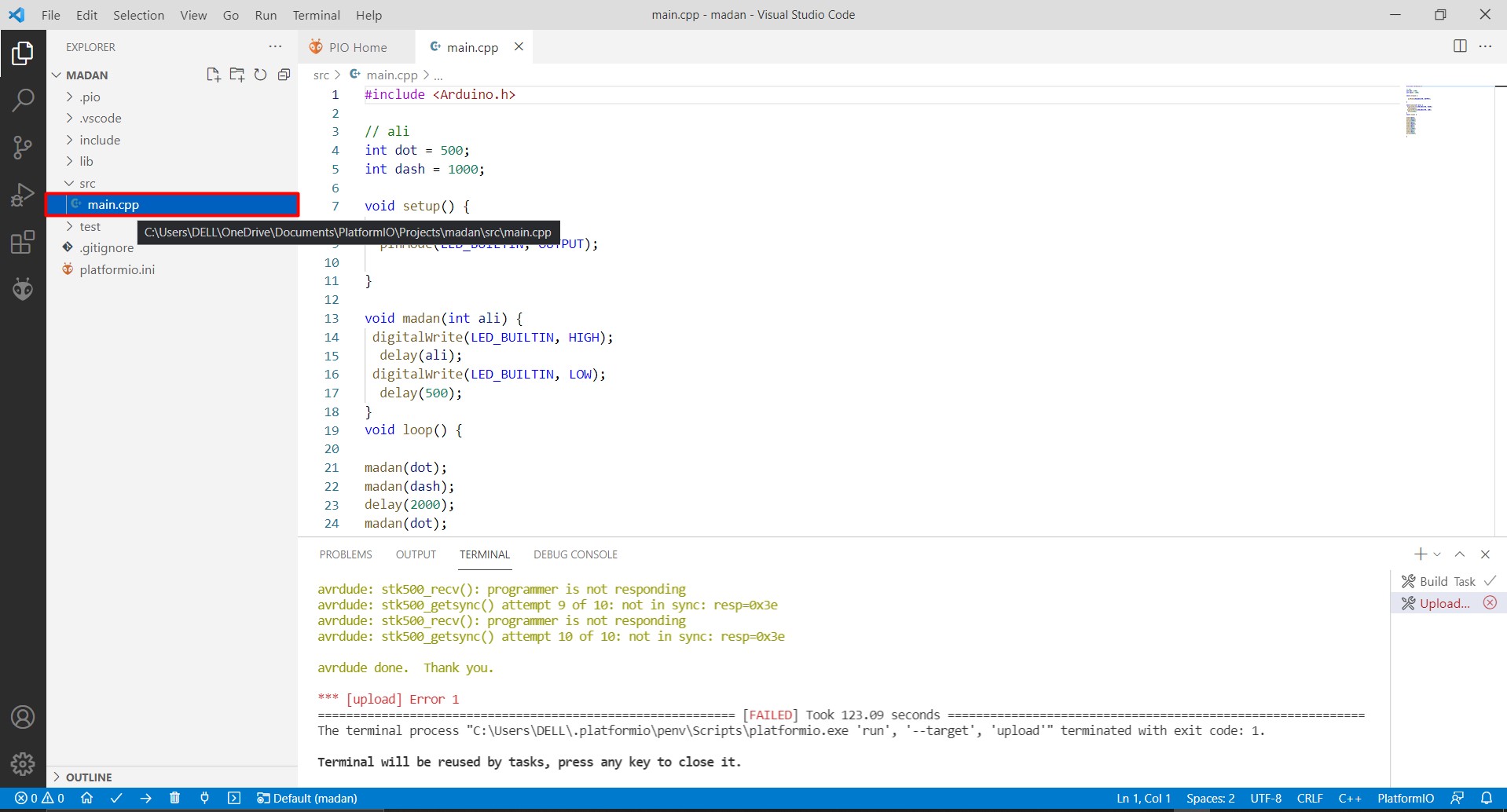
Figure 8: “main.cpp” tab
Morse Codes
Morse code is a method used in telecommunication to encode text characters as standardized sequences of two different signal durations, called dots and dashes [7].
Figure 9 showcases the morse codes.
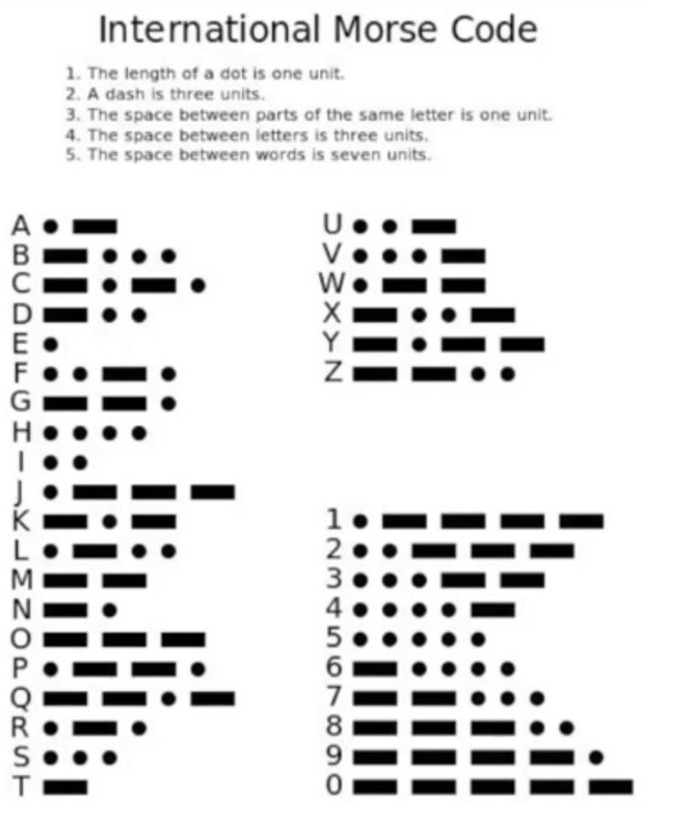
Figure 9: Morse codes
The code for the word “ALI” was written.
Firstly the time ranges for the dot and dash were identified and inside the loop there were functions named “LED_Built, High” which means the LED works and “LED_Built, Low” which means that the LED does not work.
Figure 10 showcases the aforementioned functions.
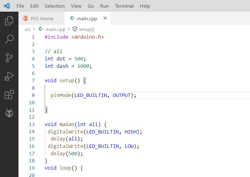
Figure 10: “LED_Built, High” and “LED_Built, Low” functions
Then the code for the words in the name “Ali” were defined as shown in Fig. (11).
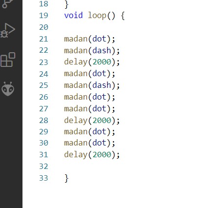
Figure 11: Code for the words “Ali”
The code for the name “Ali” is shown below:
#include <Arduino.h>

// ali
int dot = 500;
int dash = 1000;

void setup() {

  pinMode(LED_BUILTIN, OUTPUT);

}

void madan(int ali) {
 digitalWrite(LED_BUILTIN, HIGH);
  delay(ali);
 digitalWrite(LED_BUILTIN, LOW);
  delay(500);
}
void loop() {

madan(dot);
madan(dash);
delay(2000);
madan(dot);
madan(dash);
madan(dot);
madan(dot);
delay(2000);
madan(dot);
madan(dot);
delay(2000);

}
The code was tested successfully as shown in Fig. (12).
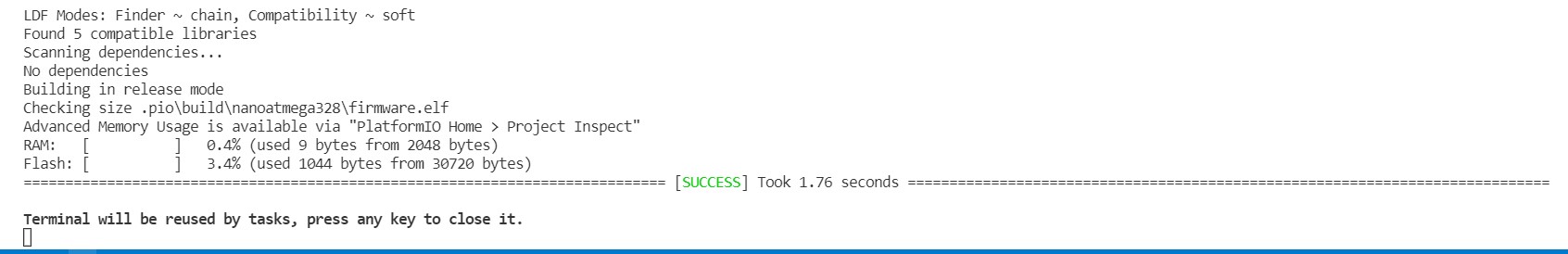
Figure 12: Code tested successfully
The code then was uploaded to the microcontroller as shown in Fig. (13).
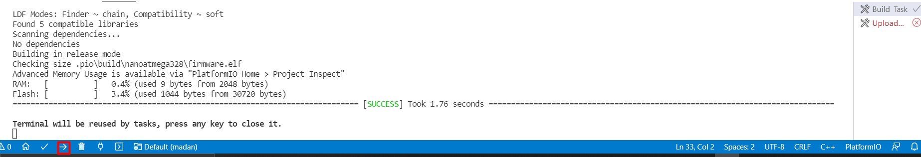
Figure 13: Code uploaded to the microcontroller
Figure 14 showcases a GIF animation of the microcontroller after the code was uploaded.
Figure 14: GIF animation of the microcontroller
References
[1](https://www.arrow.com/en/research-and-events/articles/engineering-basics-what-is-a-microcontroller#:~:text=A%20microcontroller%20(sometimes%20called%20an,designed%20to%20implement%20certain%20tasks.)