4. 3D scanning and printing
This week’s task have encompassed the utilization of 3D printers which is an additive manufacturing technology. The designs in a 3D printer cannot be designed easily using a CNC (Computer Numerical Control) machine or a laser cutter because the CNC and laser cutter machines have a certain depth in which they can drill to, whereas the 3D printer adds material till it completely designs the final product. So if a ball is to be designed, this ball has a certain depth and it can be made easily through using a 3D printer because it keeps adding material until it reaches the desired dimensions, so there are not really alot of restrictions here such as the depth restriction in the CNC and laser cutter machines [1].
3D Printing
Fusion 360 Design
A circle along with a vertical line and a horizontal rectangle were added. This is showcased in Fig. (1).
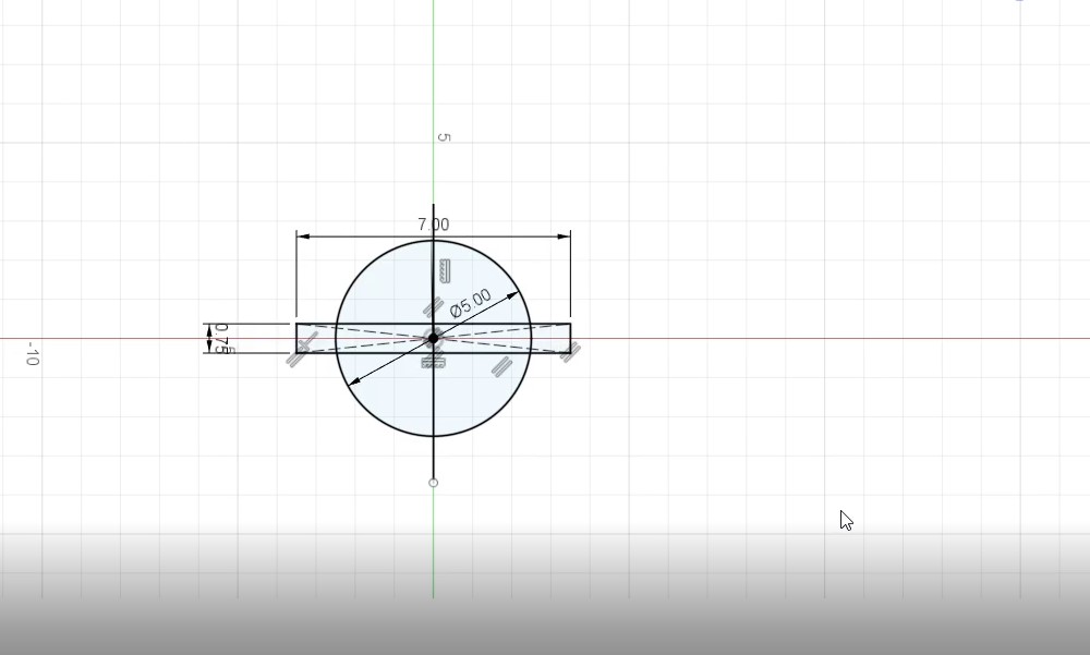
Figure 1: Adding a circle, vertical line and a horizontal rectangle
Then the revolve tool was utilized and the following shape shown in Fig. (2) was created.
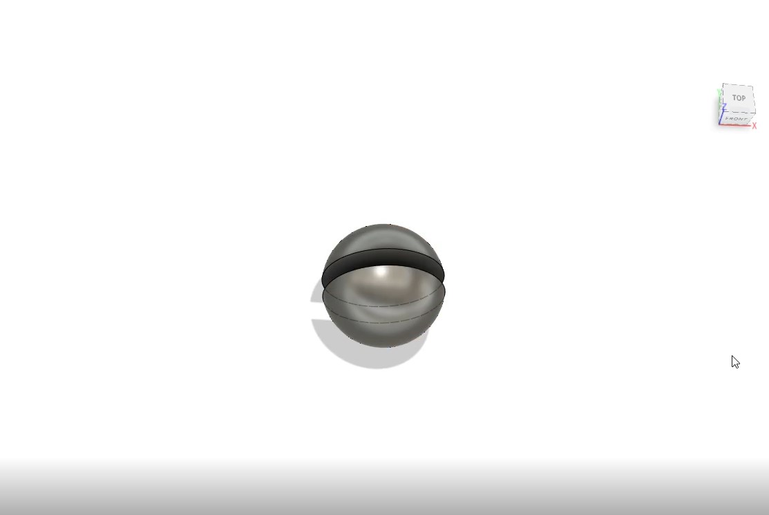
Figure 2: Utilizing the revolve tool
Then the shell tool was utilized and an inner thickness of 0.25 cm was added. This is showcased in Fig. (3).
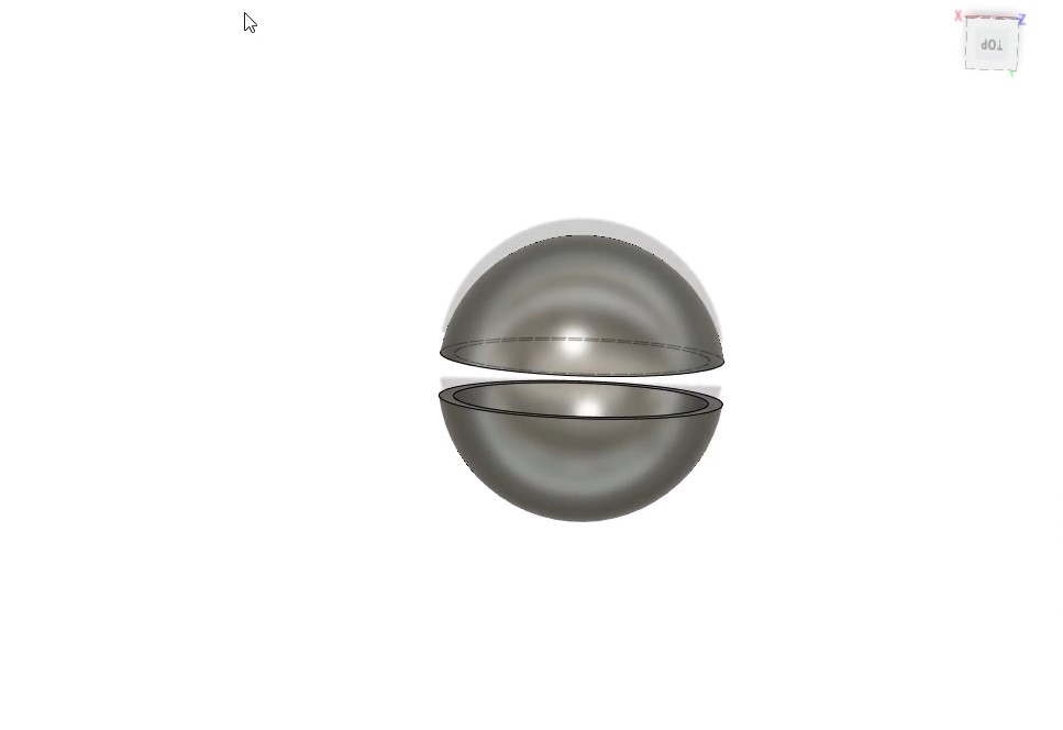
Figure 3: Utilizing the shell tool
Then a circle with a radius of 4.5 cm along with a vertical line were added. This is showcased in Fig. (4).
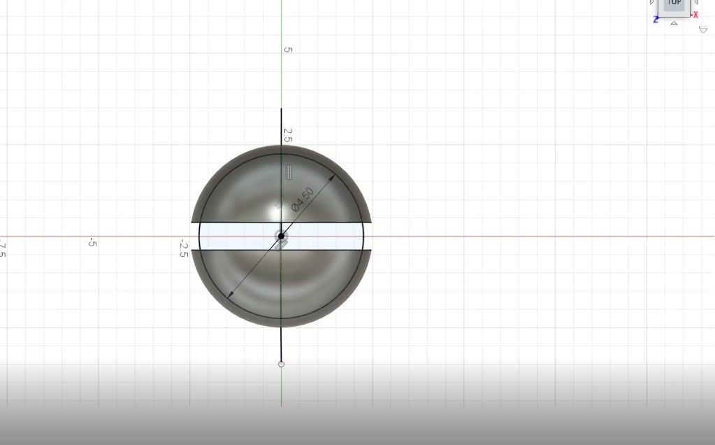
Figure 4: Adding a circle and a line.
Then the revolve tool was used and the operation was selected as a new body and the following shape shown in Fig. (5) was obtained.
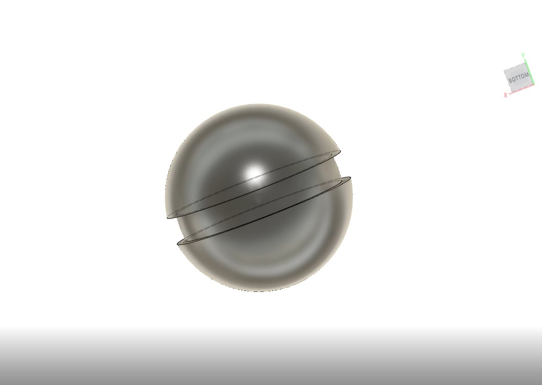
Figure 5: Using the revolve tool and selecting the operation as a new body
Moreover, several circles were made. This is showcased in Fig. (6).
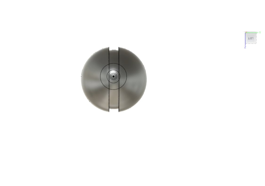
Figure 6: Making several circles
Then the object was extruded and the following shape have appeared. This is showcased in Fig. (7).
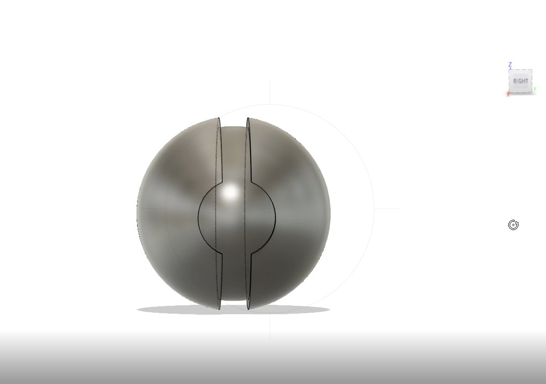
Figure 7: Extruding the object
The inner circles were extruded as shown in Fig. (8).
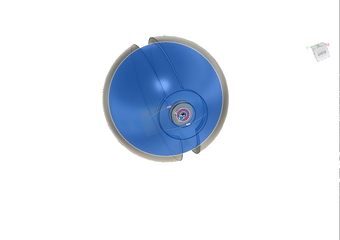
Figure 8: Extruding the inner circles
Figure 9 showcases the final design.
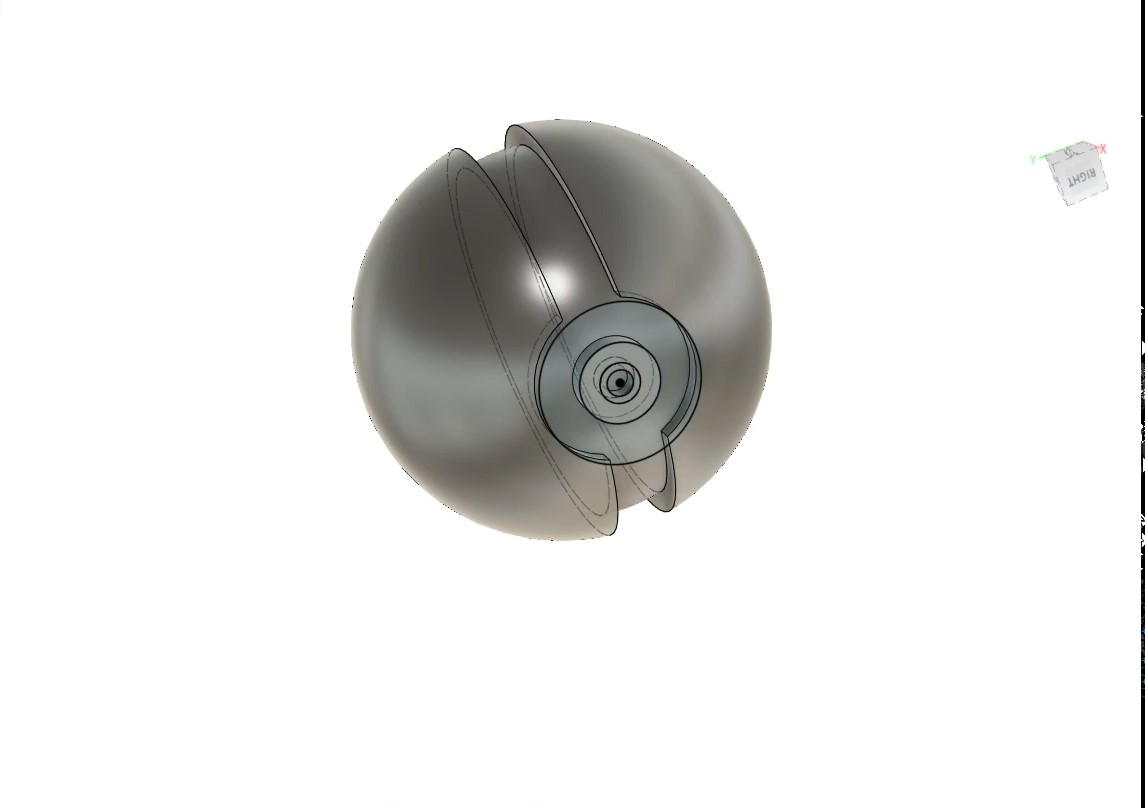
Figure 9: Final design
The designs were inserted in Ultimaker Cura program which is the software utilized by the 3D printer and here the designs can be scaled up or down, as shown in Fig. (10).
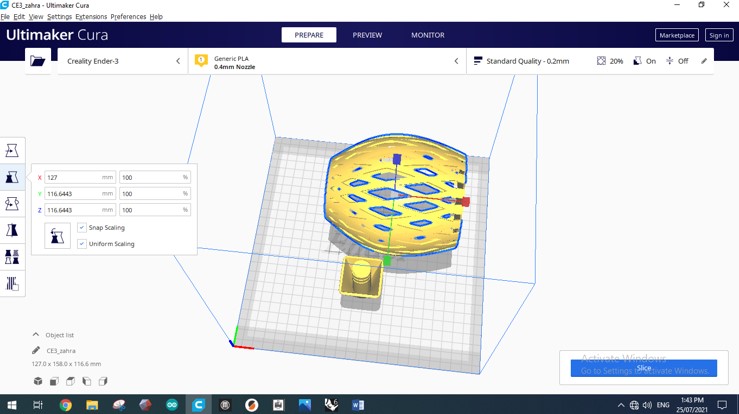
Figure 10: Scaling option in Ultimaker Cura software
The orientation was changed to reduce the amount of support needed and then the option “Slice” was pressed. This is showcased in Fig. (11).
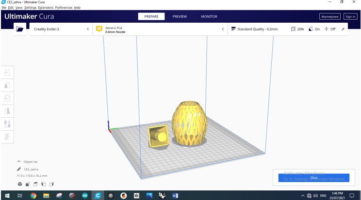
Figure 11: Changing the orientation of the design
After the “Slice” option was pressed, the elapsed time have appeared. This is showcased in Fig. (12).
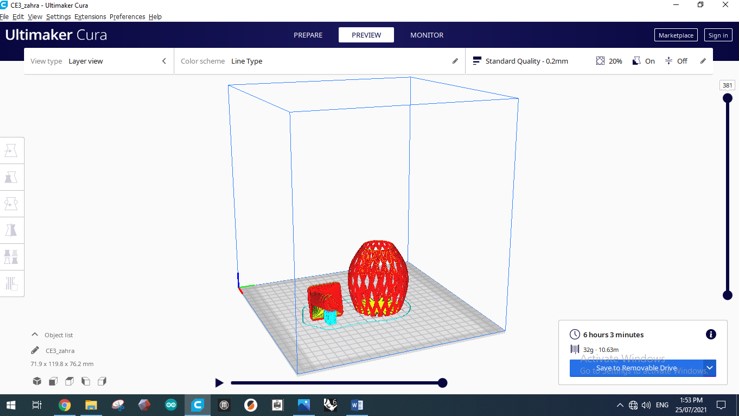
Figure 12: Appearance of the elapsed time
Moreover, the previous layer height was 0.2 mm and the number of layers were 381. Once the layer height was reduced, the number of layers has increased to 761 and this has yielded to a better design since more material was used. This is demonstrated in Fig. (13) and Fig. (14).

Figure 13: Layer height=0.2 mm
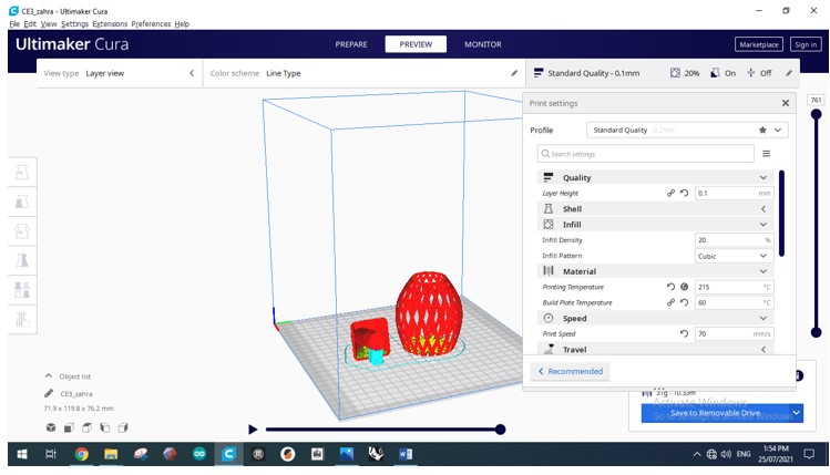
Figure 14: Layer height=0.1 mm
The printing speed was kept as 70 mm/s. If the printing speed is increased, the printing time and quality will reduce and vice versa. The printing speed is showcased in Fig. (15).
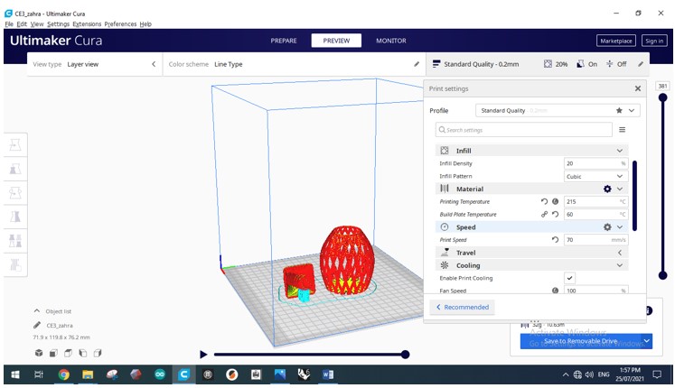
Figure 15: Setting the print speed
Figure 16 showcases the other settings that could be varied in the 3D printer.
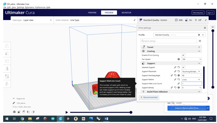
Figure 16: Other settings in the 3D printer
The following are the steps that were implemented prior to the printing process:
Firstly, the card was inserted to the device and the “Prepare” option was chosen, as shown in Fig. (17).
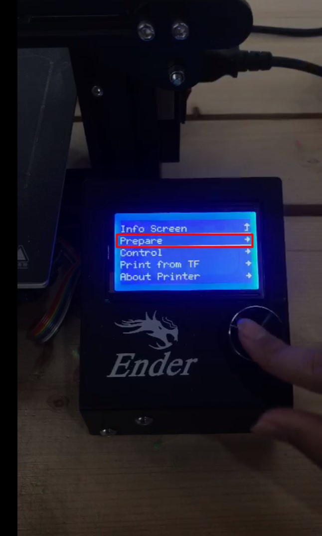
Figure 17: Choosing the “Prepare” option
Then “Preheat PLA” option was chosen to start heating the plastic as shown in Fig. (18).
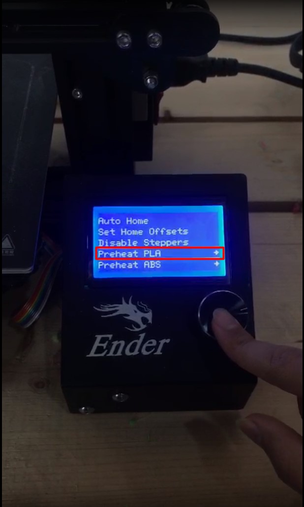
Figure 18: Choosing the “Preheat PLA” option
Then “Print from TF” option was chosen as shown in Fig. (19).
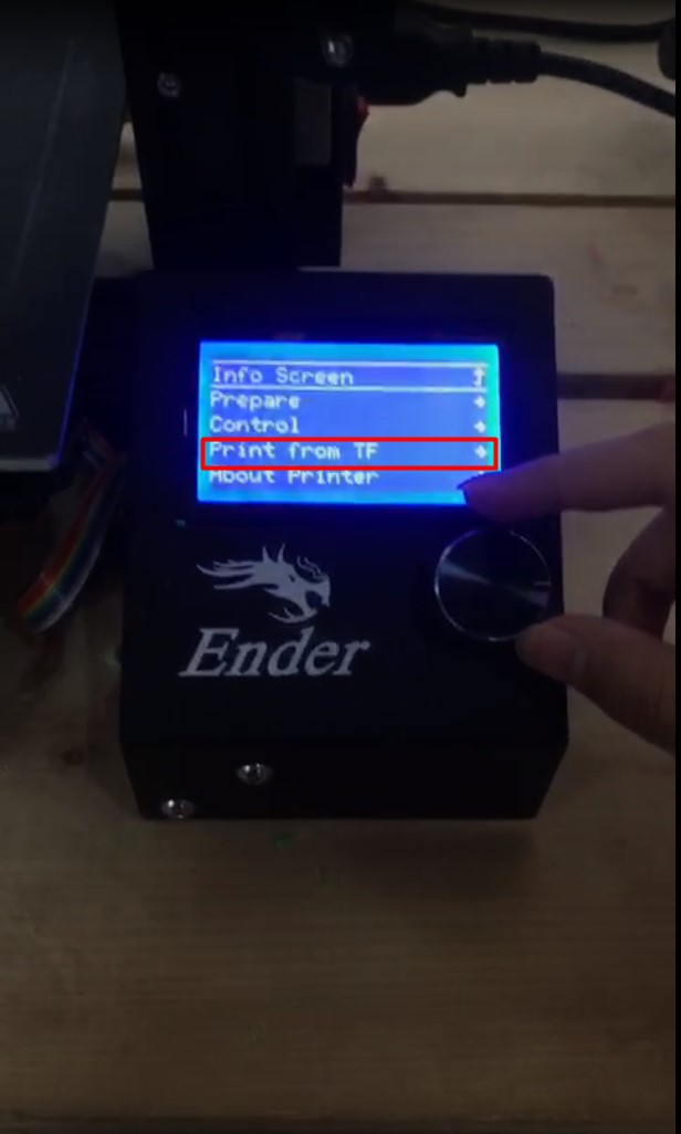
Figure 19: Choosing the “Print from TF” option
Then the file that should be printed was chosen, as shown in Fig. (20).
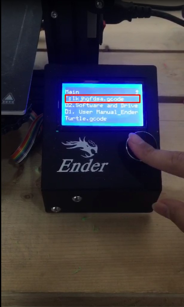
Figure 20: Choosing the file that will be printed
Then a process called “Babystep” was implemented to check the distance from the printing machine to the flexible bed and once the distance was close enough to the flexible bed, the printing process have started. Figure 21 showcases the implementation of the “Babystep” process.
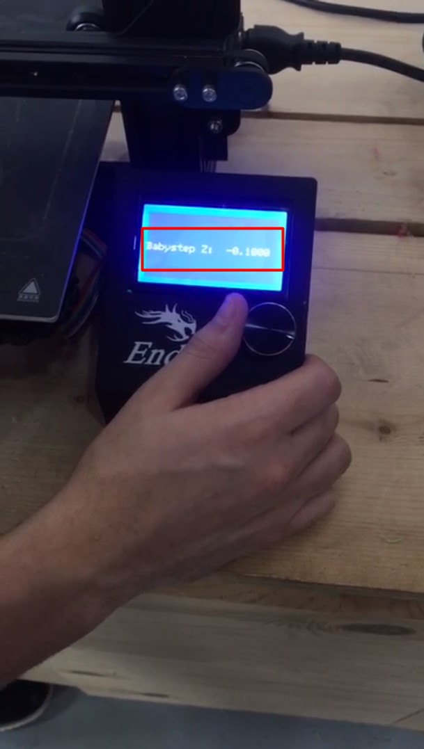
Figure 21: Implementing the “Babystep” process.
Figure 22 showcases the 3D printed design.
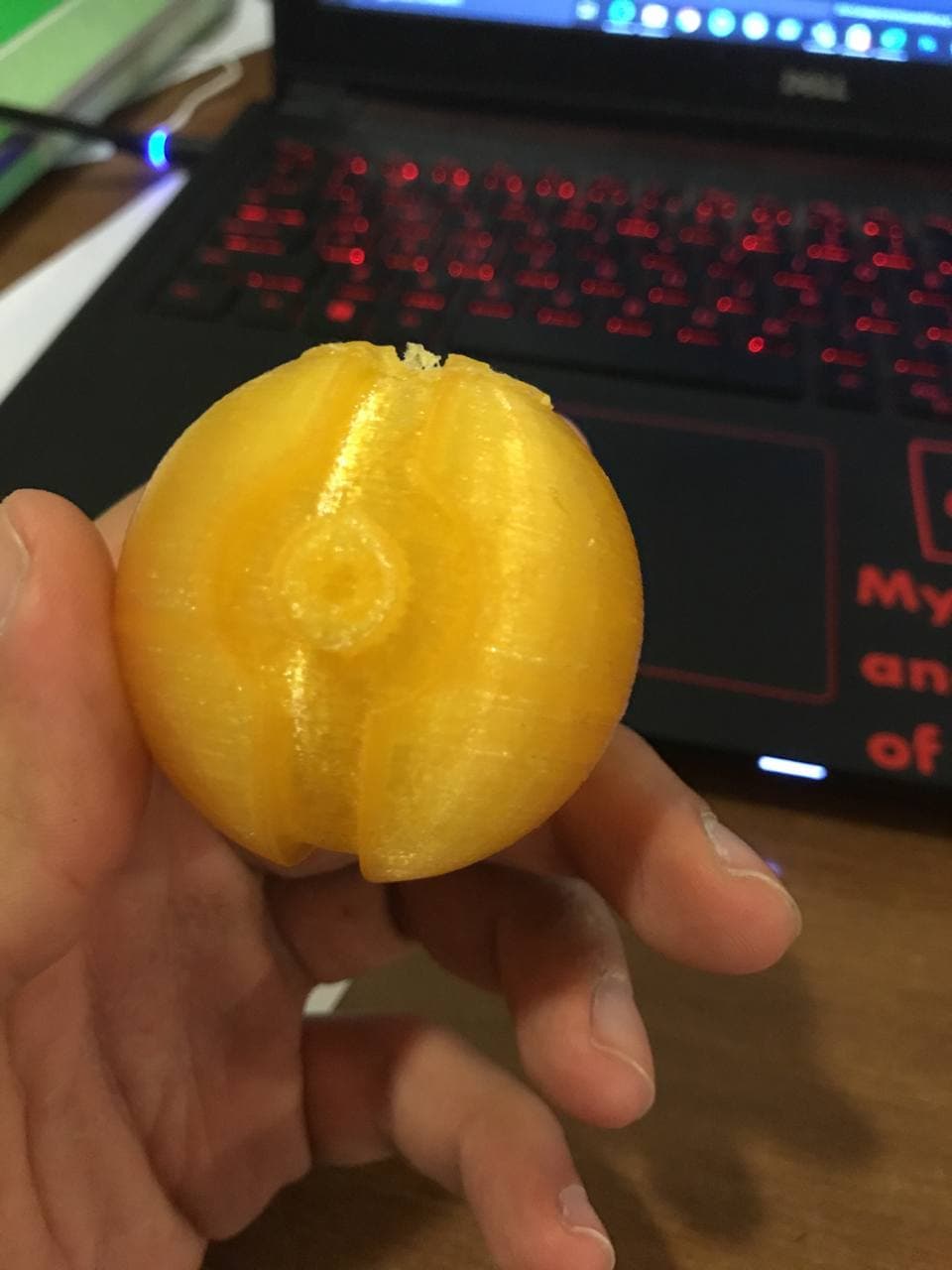
Figure 22: The final product
3D scanning
Skanect
Skanect is a 3D scanning program that allows the user to use a sensor, such as Xbox 360 Kinect, to scan objects, rooms, or even people and recreate them as computer-based 3D models [2].
The following were the steps encompassed in the 3D scanning process:
A new file was created as shown in Fig. (23).
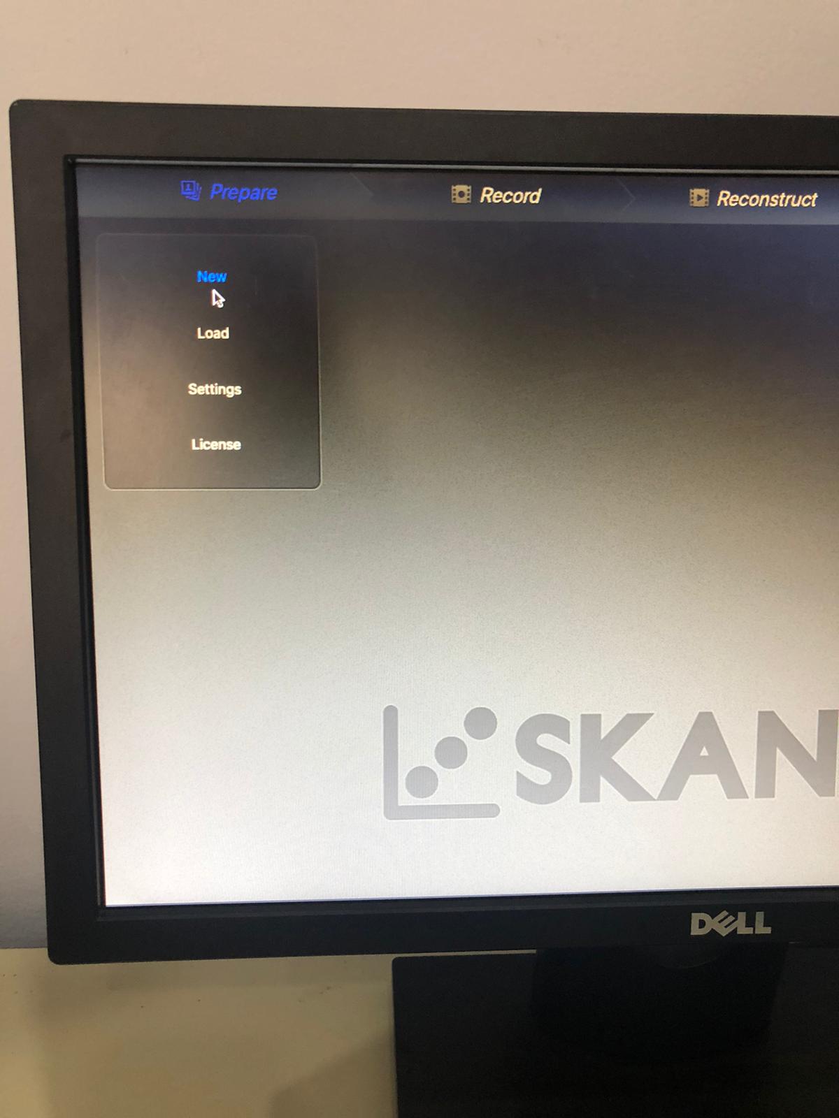
Figure 23: Creating a new file
The “Body” option was selected in order to capture the body and the “Start” option was selected. This is showcased in Fig. (24).
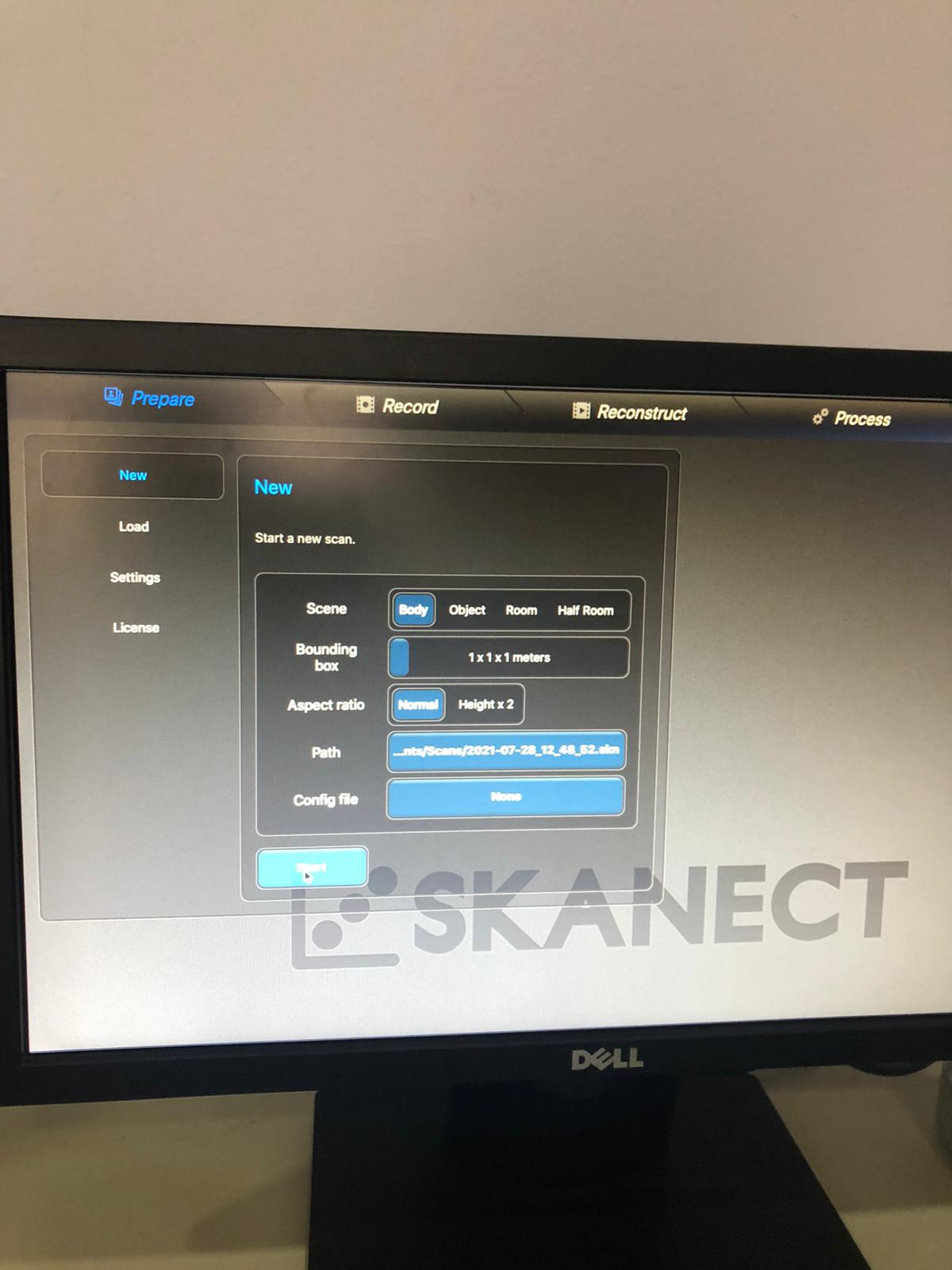
Figure 24: Selecting the “Body” option
Then the recording was started as shown in Fig. (25).
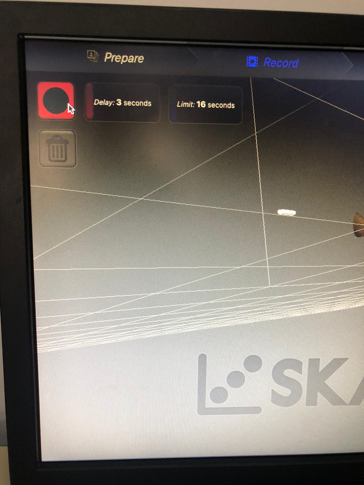
Figure 25: Recording started
Then, the body was captured by the Skanect device as shown in Fig. (26).
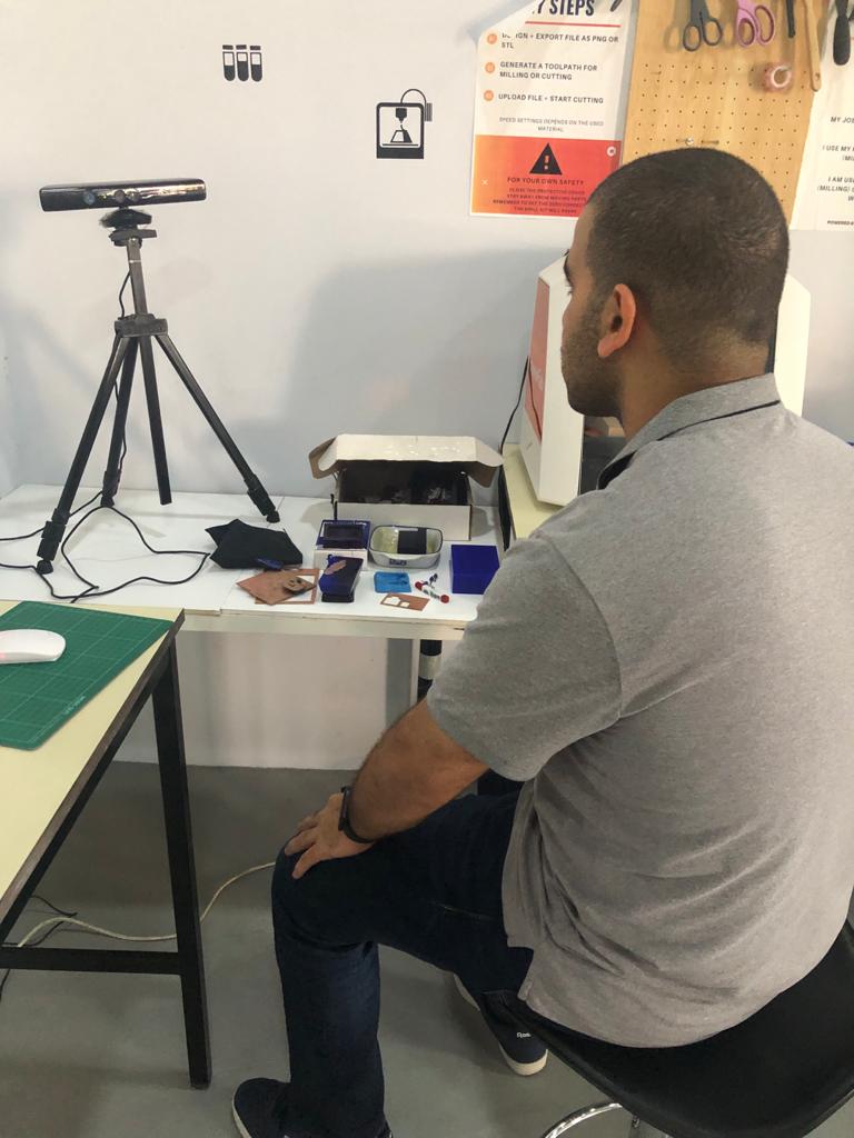
Figure 26: Body capturing process
This was the body that was captured as shown in Fig. (27).
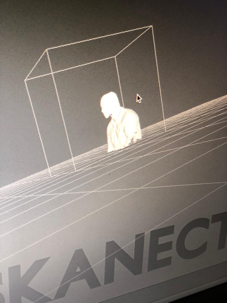
Figure 27: Body captured
There were some holes in the design, since the device was not able to capture these parts. This is shown in Fig. (28).
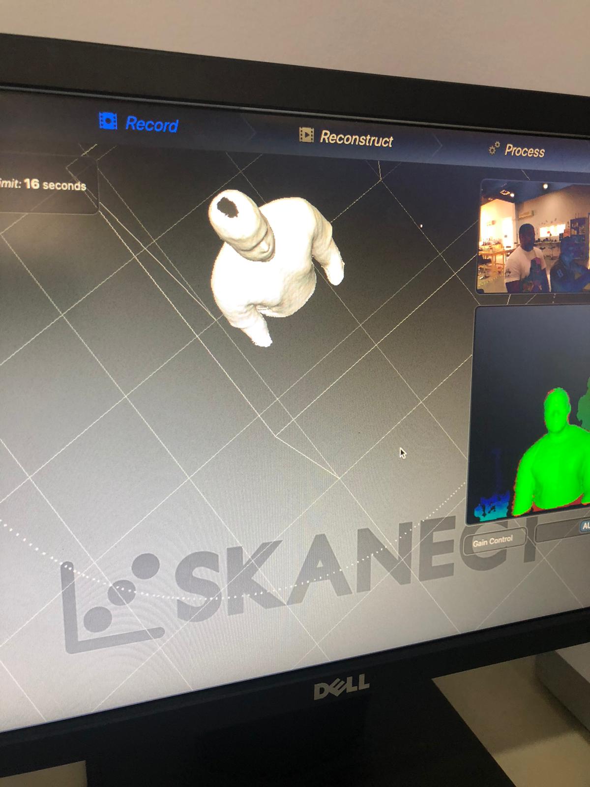
Figure 28: Holes in the design
“Watertight” option was used in an effort to fill these holes as shown in Fig. (29).
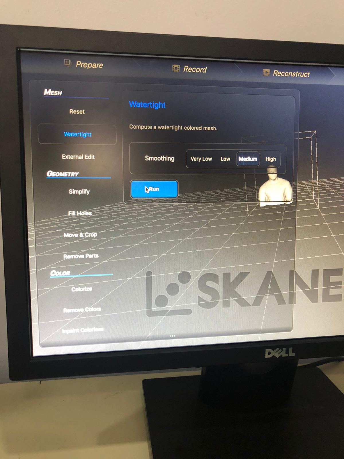
Figure 29: Watertight option
Then the design was exported as an STL, which is the file format that is compatible with the 3D printer. This is showcased in Fig. (30).
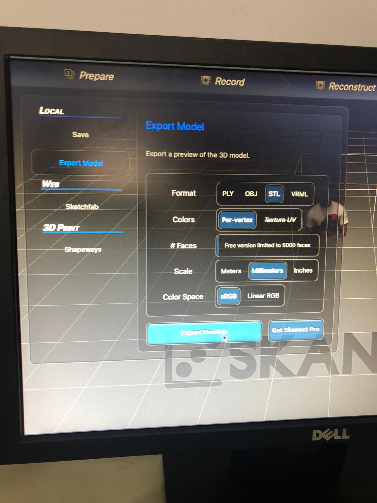
Figure 30: Exporting the file as an STL
Then the design was 3D printed as shown in Fig. (31).
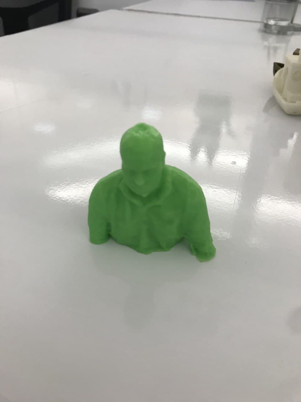
Figure 31: Final design 3D printed
Qlone
It is a mobile app which scans 3D objects using camera in the mobile [3].
The 3D object was scanned as shown in Fig. (32).
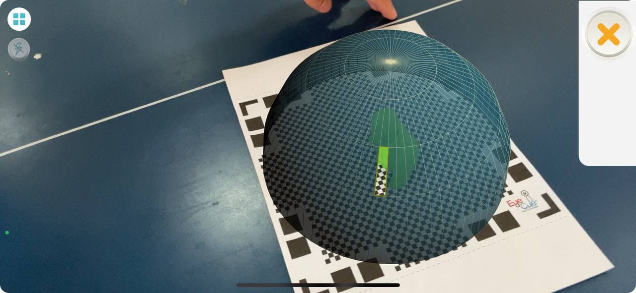
Figure 32: Scanning the 3D object
Figure 33 showcases the 3D object after it was rendered.