Project Development
The final project is focusing on creating a tool to test the strength of bio material.
Electronic Programing
Our aim is to program an electronic load testing object to test tensile strength of the adhesive. In this part LCD, load cell and humidity and temperature sensor are all connected to each other through Arduino nano micro controller.
LCD Display Sensor JHD 162A
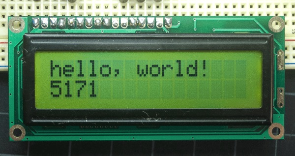
Liquid crystal display allows you to display different characters and numbers. JHD 162A is 16*2 LCD which consist of two lines and each one can display up to 16 characters and numbers. The aim of this LCD is to display load strength. Also, temperature and humidity of the atmosphere will be displayed on the screen to set standard for our testing procedure. This part is just to test that both DHT11 sensor and LCD work probably.
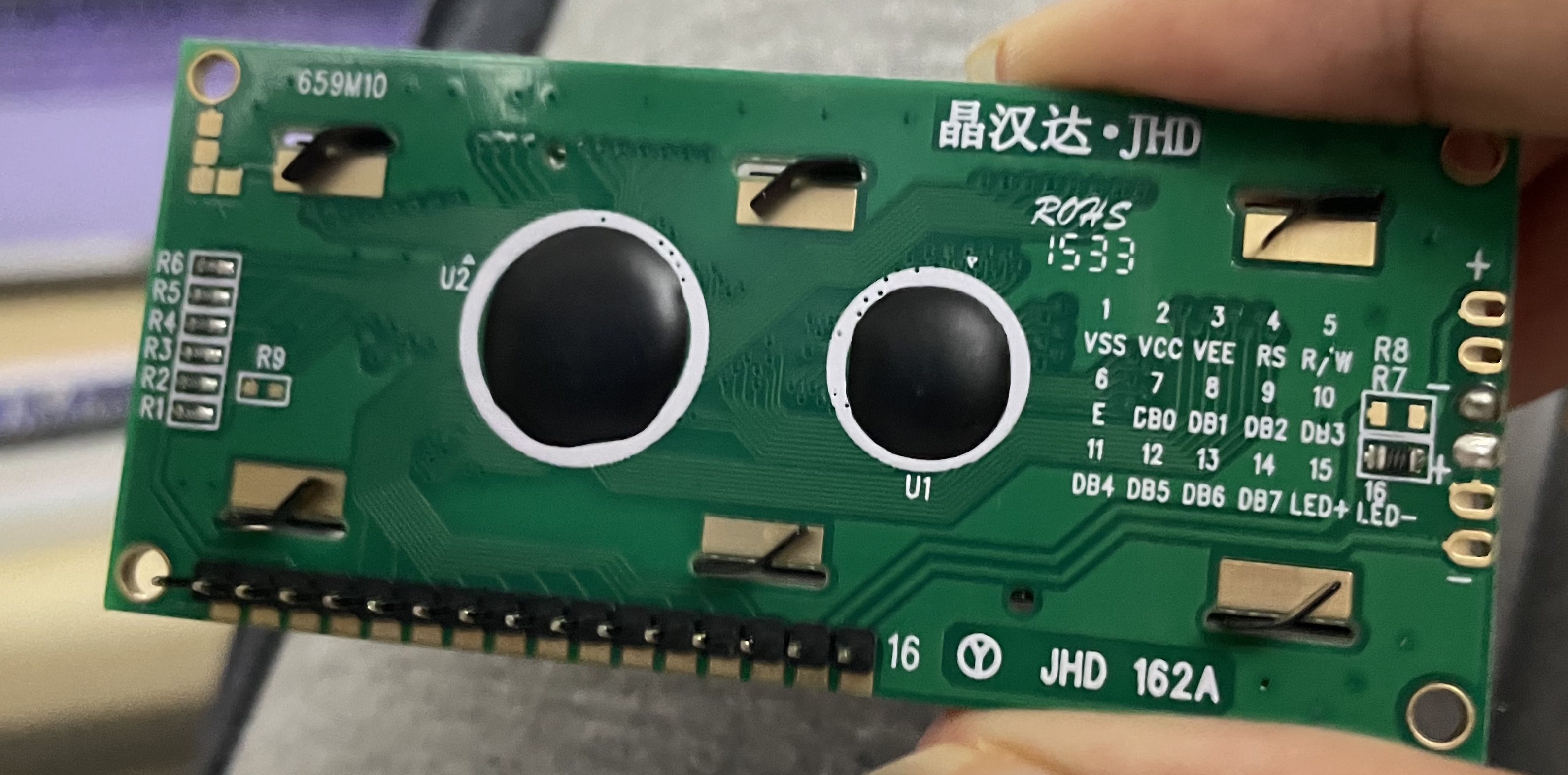
Pins Explained
There are 16 pins in the sensor.
1 VSS is the ground which used as a reference point to measure voltage.
2 VCC is the power supply 5 V from Arduino to sensor.
3 VEE is contrast adjustment pin which is used to adjust. This pin is attached to potential meter (10 kohm) which has varying voltage (normally between 0.4 to 0.9 V). I have connected this pin to ground after measuring voltage between potential meter which is almost zero at maximum contrast.
4 RS is the register pin. It is used to register commands and data to sensor.
5 R/W is read/write and it is used to select read or write mode.
6 E is enable pin that enables writing to the registers.
7 to 14 are data bus pins which is what you write to a register or what you read on the LCD.
15 is the anode of the backlight LED.
16 is the cathode of the backlight LED.
Code Example
// include the library code:

// This library for LCD sensor

#include <LiquidCrystal.h>

// This library for humidity and temperature sensor

#include <dht.h>
dht DHT;

// Signal pin is attached to pin A5

#define DHT11_PIN A5

// initialize the library by associating any needed LCD interface pin
// with the arduino pin number it is connected to
const int rs = 12, en = 11, d4 = 5, d5 = 4, d6 = 3, d7 = 2;

LiquidCrystal lcd(rs, en, d4, d5, d6, d7);

void setup() {

// This is the speed of exchanging values between Arduino and serial monitor.

  Serial.begin(9600);

  // Initialize the interface and specifies dimensions (characters at each row, number of rows)

  lcd.begin(16, 2);


}

void loop() {
  // set the cursor to column 0, line 1
  // (note: line 1 is the second row, since counting begins with 0):

// serial.println is used to print values in serial monitor (This step is used to test DHT11 sensor before connecting it to display )

// lce.print is used to print values to lcd screen

  int chk = DHT.read11(DHT11_PIN);

  Serial.println(DHT.temperature);

  Serial.println(DHT.humidity);
  lcd.print("Temperature=");
  lcd.print(DHT.temperature);

  // Move printing to lcd to the begining of the second row (column, row)

   lcd.setCursor(0, 1);
  lcd.print("Humidity=");

lcd.print(DHT.humidity);

//Delay between each reading it should be two seconds. According to out testing this sensor will not work probably if delay is set to one second only.

  delay(10000);
}
Code is explained in comments
Load Cell With HX711 and Arduino
In this week we tried to connect a load cell with amplifier and Arduino.
Load cell is attached to two resistors (1 kilo ohm for each). Load cell is connected to amplifier (HX711) which amplifies signal to make it readable in other devices (Arduino).
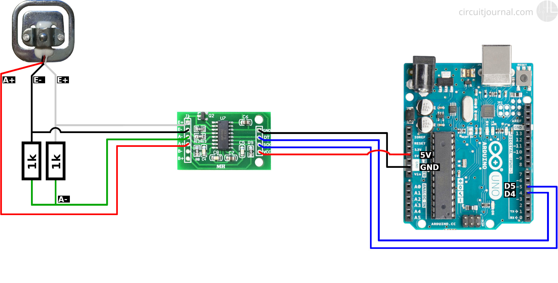
Resistors and pins of HX711 are attached using soldering machine and soldering wires.
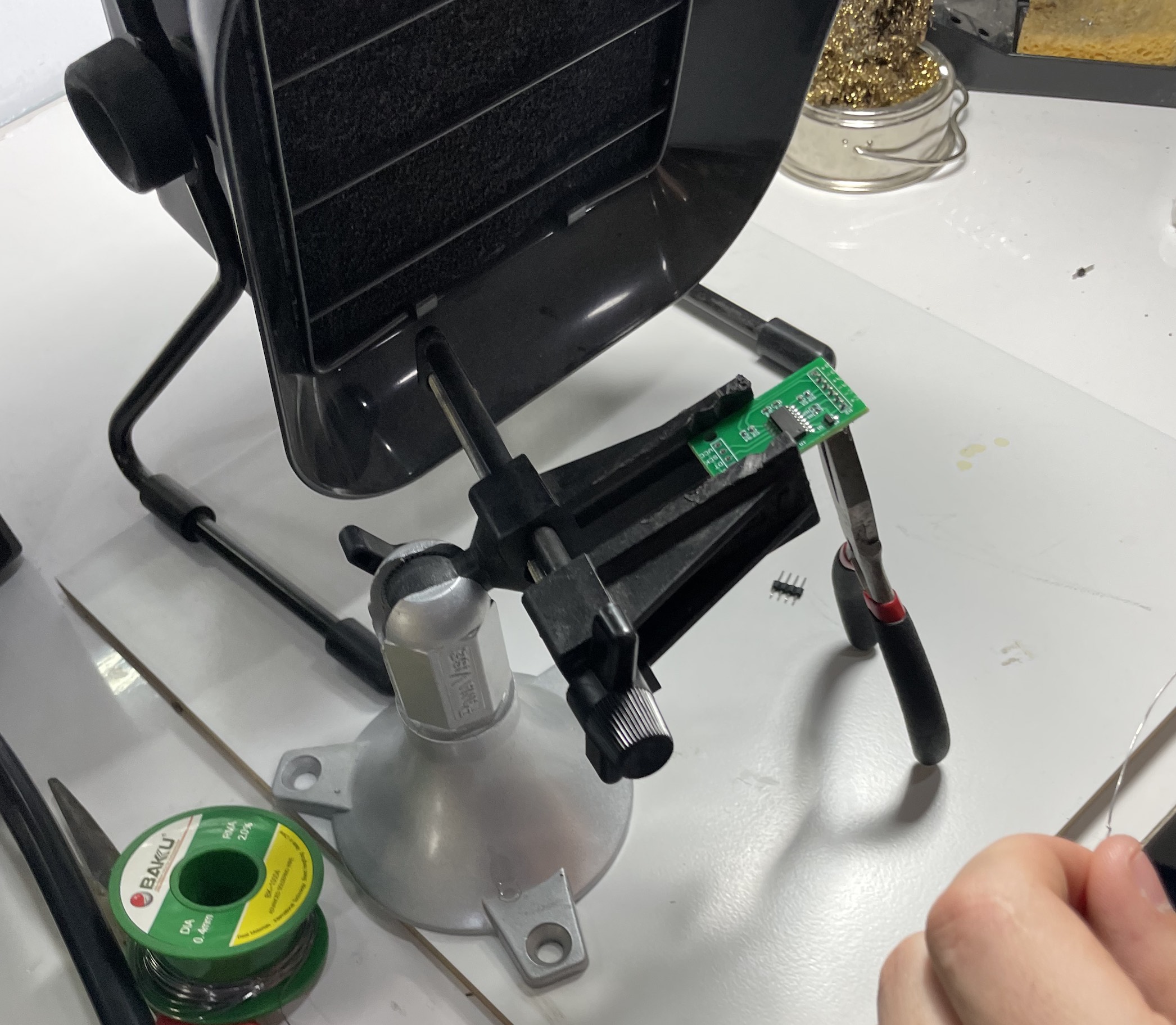
All parts are connected to each other.
Library hx711 adc is used to test this load cell. Example calibration code is used to calibrate and test load cell.
Calibration Code
(availble in example after installing library)
/*
-------------------------------------------------------------------------------------
HX711_ADC
Arduino library for HX711 24-Bit Analog-to-Digital Converter for Weight Scales
Olav Kallhovd sept2017
-------------------------------------------------------------------------------------
*/
/*
This example file shows how to calibrate the load cell and optionally store the calibration
value in EEPROM, and also how to change the value manually.
The result value can then later be included in your project sketch or fetched from EEPROM.
To implement calibration in your project sketch the simplified procedure is as follow:
LoadCell.tare();
//place known mass
LoadCell.refreshDataSet();
float newCalibrationValue = LoadCell.getNewCalibration(known_mass);
*/
#include <HX711_ADC.h>
#if defined(ESP8266)|| defined(ESP32) || defined(AVR)
#include <EEPROM.h>
#endif
//pins:
const int HX711_dout = 4; //mcu > HX711 dout pin
const int HX711_sck = 5; //mcu > HX711 sck pin
//HX711 constructor:
HX711_ADC LoadCell(HX711_dout, HX711_sck);
const int calVal_eepromAdress = 0;
unsigned long t = 0;
void setup() {
Serial.begin(57600); delay(10);
Serial.println();
Serial.println("Starting...");
LoadCell.begin();
unsigned long stabilizingtime = 2000; // preciscion right after power-up can be improved by adding a few seconds of stabilizing time
boolean _tare = true; //set this to false if you don't want tare to be performed in the next step
LoadCell.start(stabilizingtime, _tare);
if (LoadCell.getTareTimeoutFlag() || LoadCell.getSignalTimeoutFlag()) {
Serial.println("Timeout, check MCU>HX711 wiring and pin designations");
while (1);
}
else {
LoadCell.setCalFactor(1.0); // user set calibration value (float), initial value 1.0 may be used for this sketch
Serial.println("Startup is complete");
}
while (!LoadCell.update());
calibrate(); //start calibration procedure
}
void loop() {
static boolean newDataReady = 0;
const int serialPrintInterval = 0; //increase value to slow down serial print activity
// check for new data/start next conversion:
if (LoadCell.update()) newDataReady = true;
// get smoothed value from the dataset:
if (newDataReady) {
if (millis() > t + serialPrintInterval) {
float i = LoadCell.getData();
Serial.print("Load_cell output val: ");
Serial.println(i);
newDataReady = 0;
t = millis();
}
}
// receive command from serial terminal
if (Serial.available() > 0) {
char inByte = Serial.read();
if (inByte == 't') LoadCell.tareNoDelay(); //tare
else if (inByte == 'r') calibrate(); //calibrate
else if (inByte == 'c') changeSavedCalFactor(); //edit calibration value manually
}
// check if last tare operation is complete
if (LoadCell.getTareStatus() == true) {
Serial.println("Tare complete");
}
}
void calibrate() {
Serial.println("***");
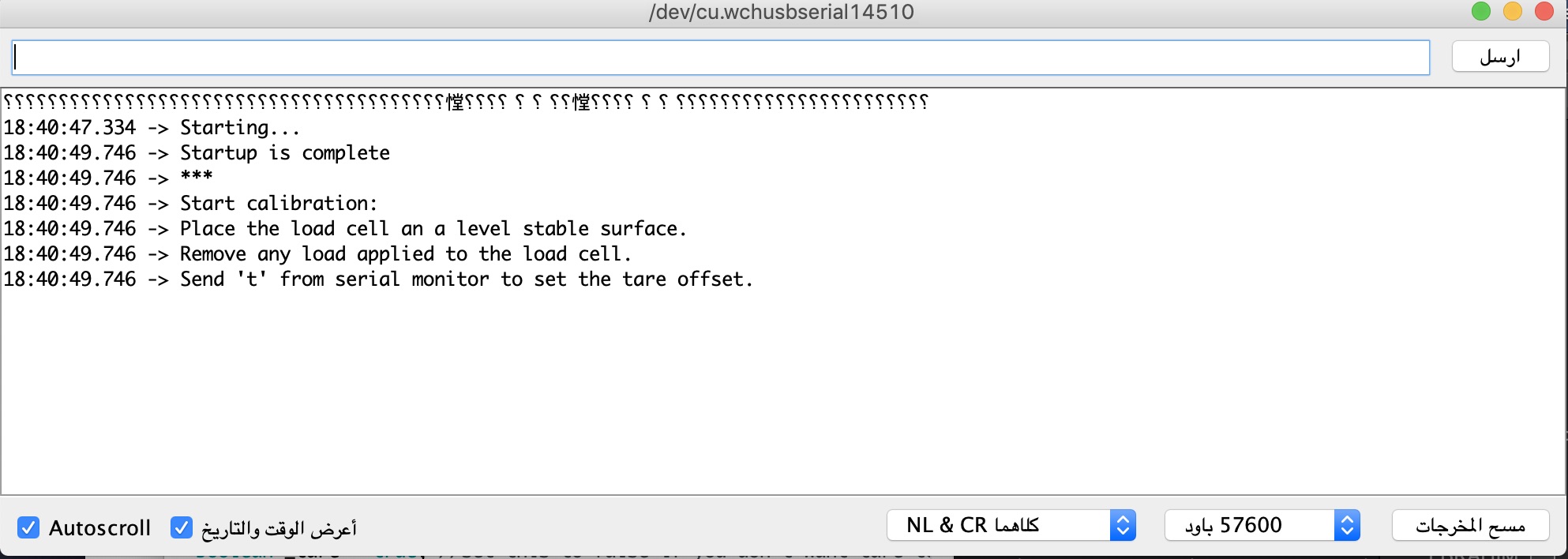
Serial.println("Start calibration:");
Serial.println("Place the load cell an a level stable surface.");
Serial.println("Remove any load applied to the load cell.");
Serial.println("Send 't' from serial monitor to set the tare offset.");
boolean _resume = false;
while (_resume == false) {
LoadCell.update();
if (Serial.available() > 0) {
if (Serial.available() > 0) {
char inByte = Serial.read();
if (inByte == 't') LoadCell.tareNoDelay();
}
}
if (LoadCell.getTareStatus() == true) {
Serial.println("Tare complete");
_resume = true;
}
}
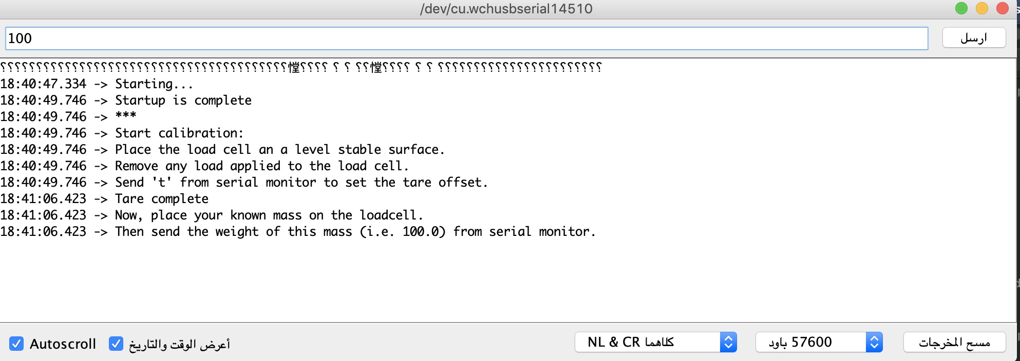
Serial.println("Now, place your known mass on the loadcell.");
Serial.println("Then send the weight of this mass (i.e. 100.0) from serial monitor.");
float known_mass = 0;
_resume = false;
while (_resume == false) {
LoadCell.update();
if (Serial.available() > 0) {
known_mass = Serial.parseFloat();
if (known_mass != 0) {
Serial.print("Known mass is: ");
Serial.println(known_mass);
_resume = true;
}
}
}
LoadCell.refreshDataSet(); //refresh the dataset to be sure that the known mass is measured correct
float newCalibrationValue = LoadCell.getNewCalibration(known_mass); //get the new calibration value
Serial.print("New calibration value has been set to: ");
Serial.print(newCalibrationValue);
Serial.println(", use this as calibration value (calFactor) in your project sketch.");
Serial.print("Save this value to EEPROM adress ");
Serial.print(calVal_eepromAdress);
Serial.println("? y/n");
_resume = false;
while (_resume == false) {
if (Serial.available() > 0) {
char inByte = Serial.read();
if (inByte == 'y') {
#if defined(ESP8266)|| defined(ESP32)
EEPROM.begin(512);
#endif
EEPROM.put(calVal_eepromAdress, newCalibrationValue);
#if defined(ESP8266)|| defined(ESP32)
EEPROM.commit();
#endif
EEPROM.get(calVal_eepromAdress, newCalibrationValue);
Serial.print("Value ");
Serial.print(newCalibrationValue);
Serial.print(" saved to EEPROM address: ");
Serial.println(calVal_eepromAdress);
_resume = true;
}
else if (inByte == 'n') {
Serial.println("Value not saved to EEPROM");
_resume = true;
}
}
}
Serial.println("End calibration");
Serial.println("***");
Serial.println("To re-calibrate, send 'r' from serial monitor.");
Serial.println("For manual edit of the calibration value, send 'c' from serial monitor.");
Serial.println("***");
}
void changeSavedCalFactor() {
float oldCalibrationValue = LoadCell.getCalFactor();
boolean _resume = false;
Serial.println("***");
Serial.print("Current value is: ");
Serial.println(oldCalibrationValue);
Serial.println("Now, send the new value from serial monitor, i.e. 696.0");
float newCalibrationValue;
while (_resume == false) {
if (Serial.available() > 0) {
newCalibrationValue = Serial.parseFloat();
if (newCalibrationValue != 0) {
Serial.print("New calibration value is: ");
Serial.println(newCalibrationValue);
LoadCell.setCalFactor(newCalibrationValue);
_resume = true;
}
}
}
_resume = false;
Serial.print("Save this value to EEPROM adress ");
Serial.print(calVal_eepromAdress);
Serial.println("? y/n");
while (_resume == false) {
if (Serial.available() > 0) {
char inByte = Serial.read();
if (inByte == 'y') {
#if defined(ESP8266)|| defined(ESP32)
EEPROM.begin(512);
#endif
EEPROM.put(calVal_eepromAdress, newCalibrationValue);
#if defined(ESP8266)|| defined(ESP32)
EEPROM.commit();
#endif
EEPROM.get(calVal_eepromAdress, newCalibrationValue);
Serial.print("Value ");
Serial.print(newCalibrationValue);
Serial.print(" saved to EEPROM address: ");
Serial.println(calVal_eepromAdress);
_resume = true;
}
else if (inByte == 'n') {
Serial.println("Value not saved to EEPROM");
_resume = true;
}
}
}
Serial.println("End change calibration value");
Serial.println("***");
}
Unfortunately values were varying rapidly even without touching the load cell. To avoid these issues we decided to simplify our design by using rectangle load cell which does not require to attach any resistor because four resistors are already placed inside the load cell. Difference in resistors is really important in this load cell since it measures weight by resistance.
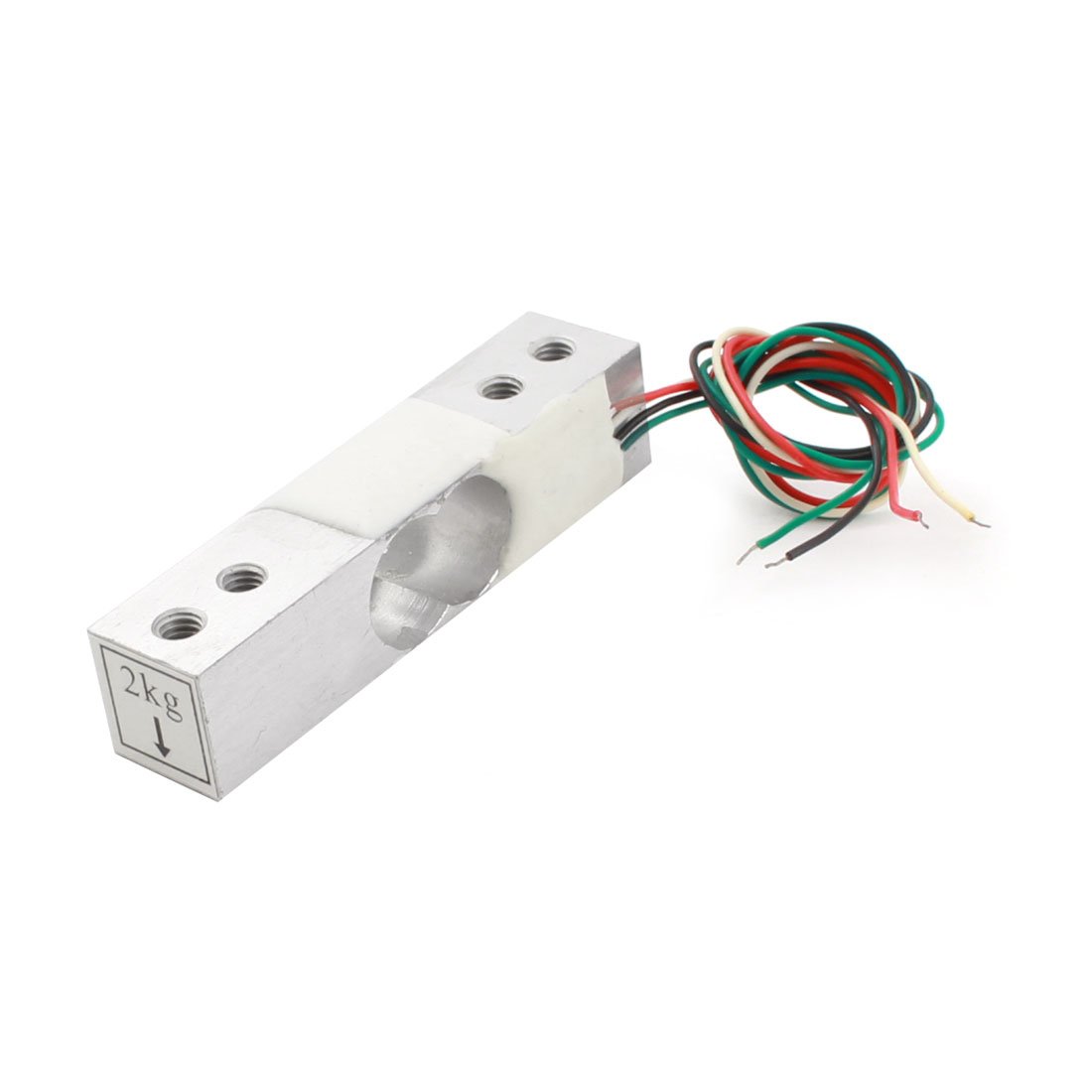
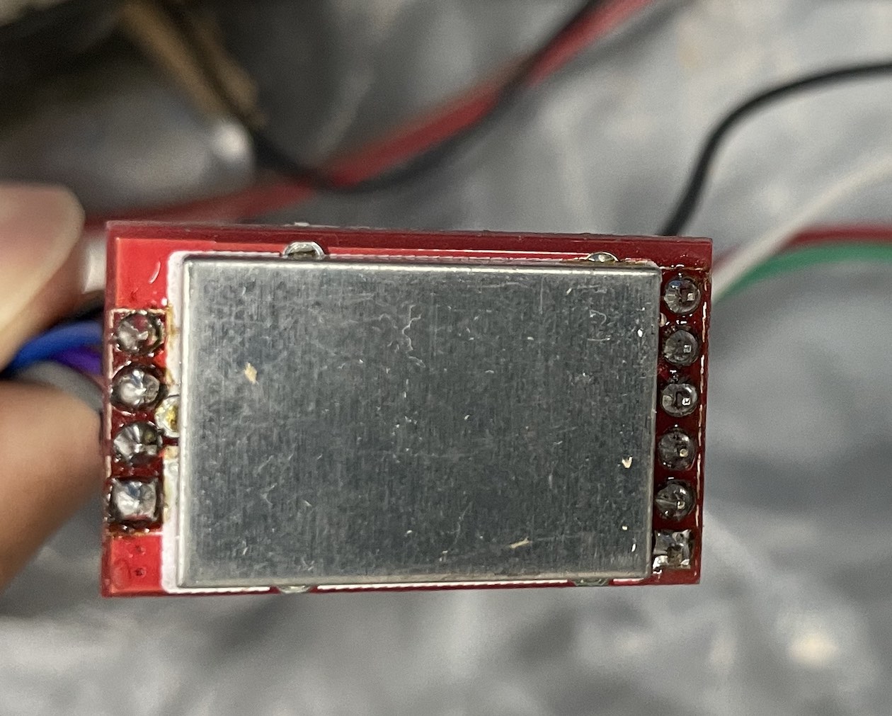
Rectangle Load Cell
This load cell contains four resistors and deformation occurs after placing weight in one side of the load cell.
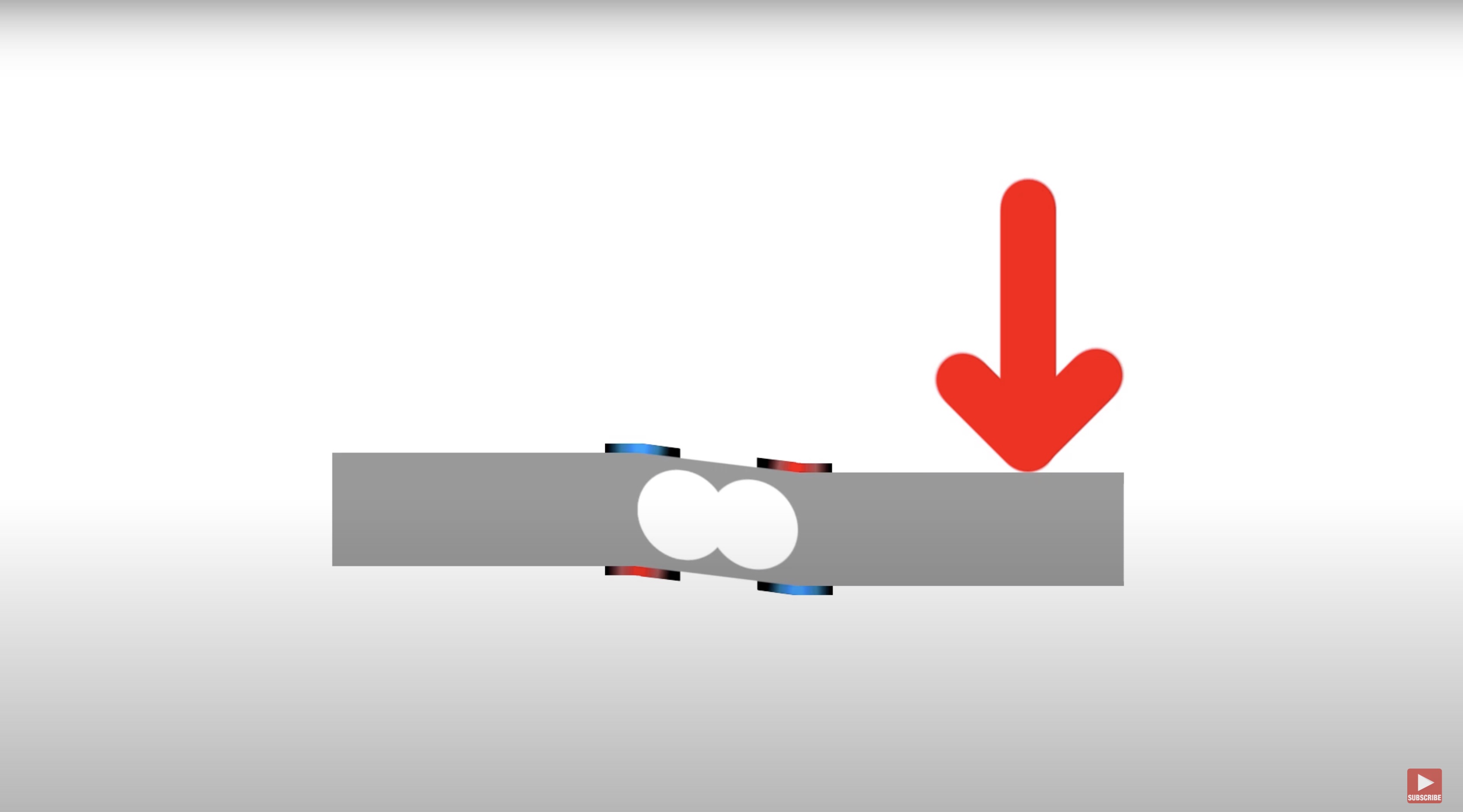
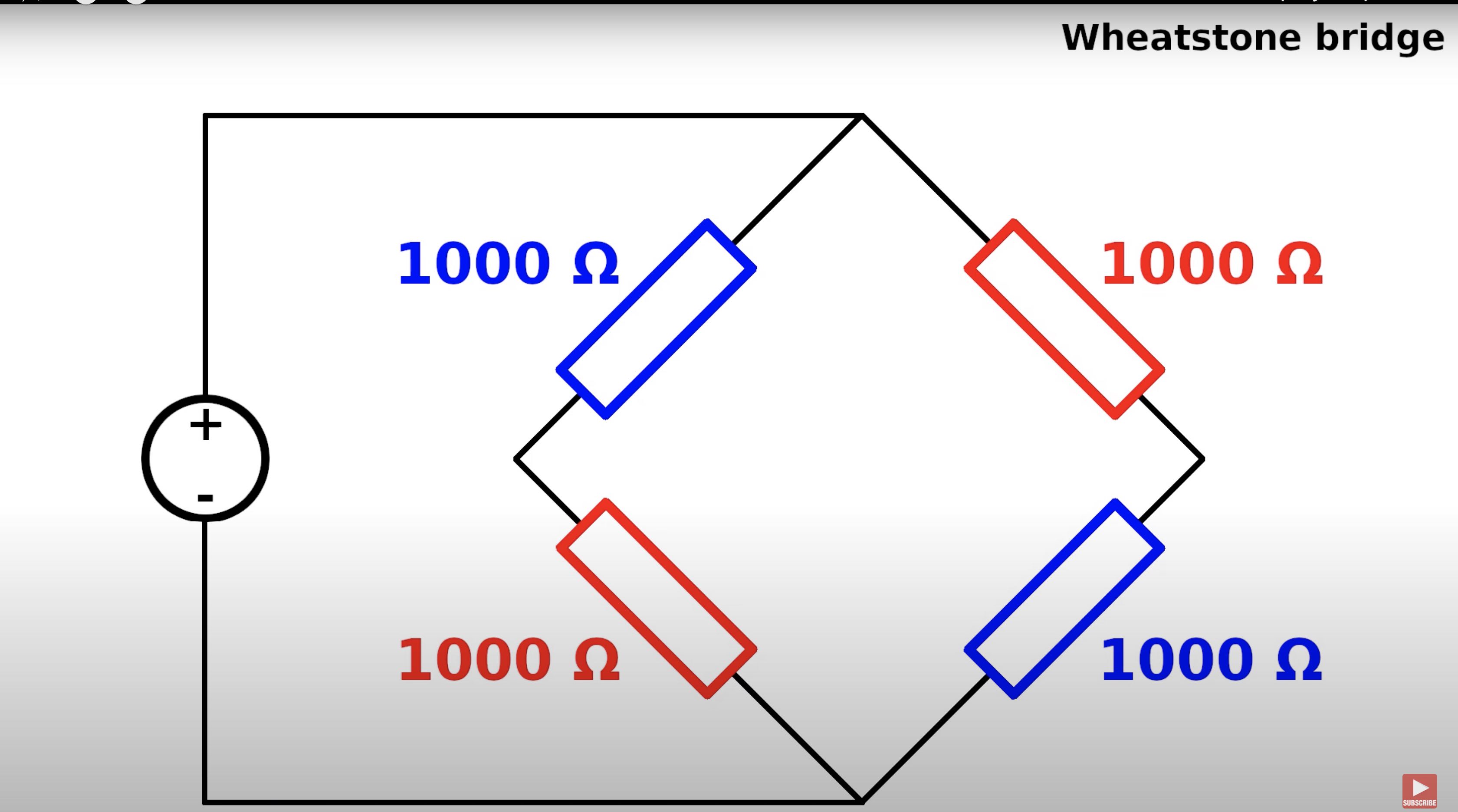
Wheatstone bridge method is used to measure the resistance to find the weight.
E+ and E- are the power wires. while A+ and A- are measurements wires. Measurements wires are sent to amplifier.
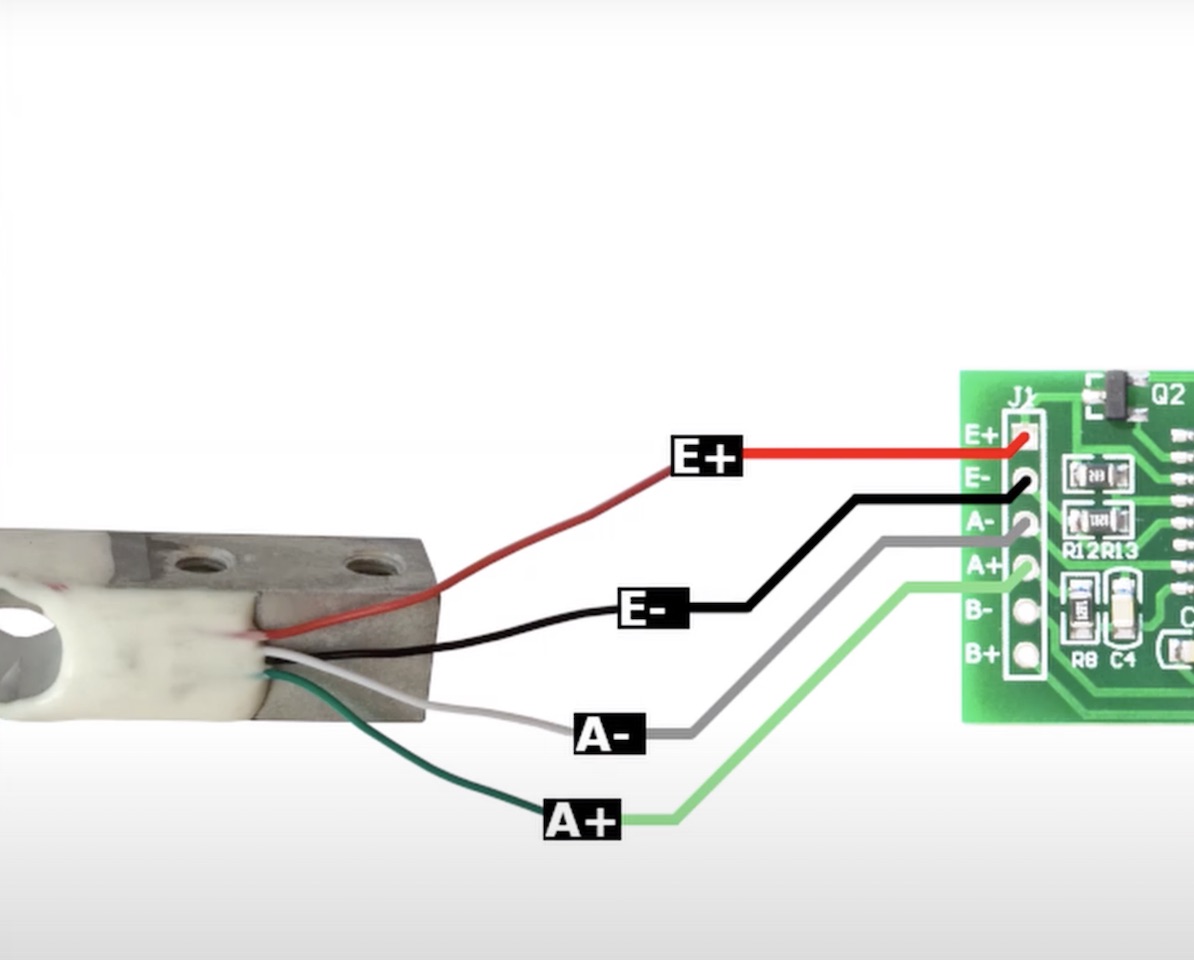
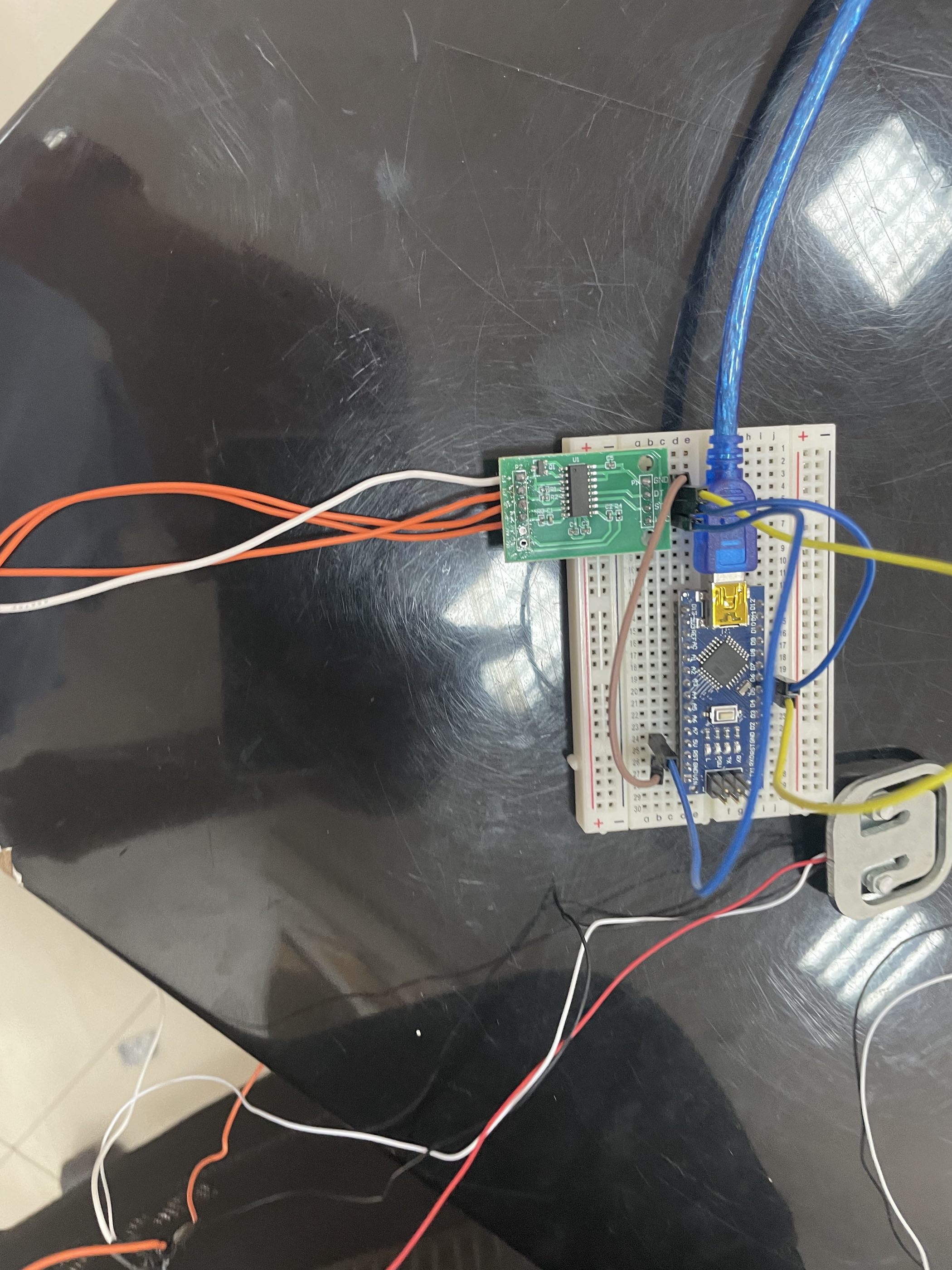
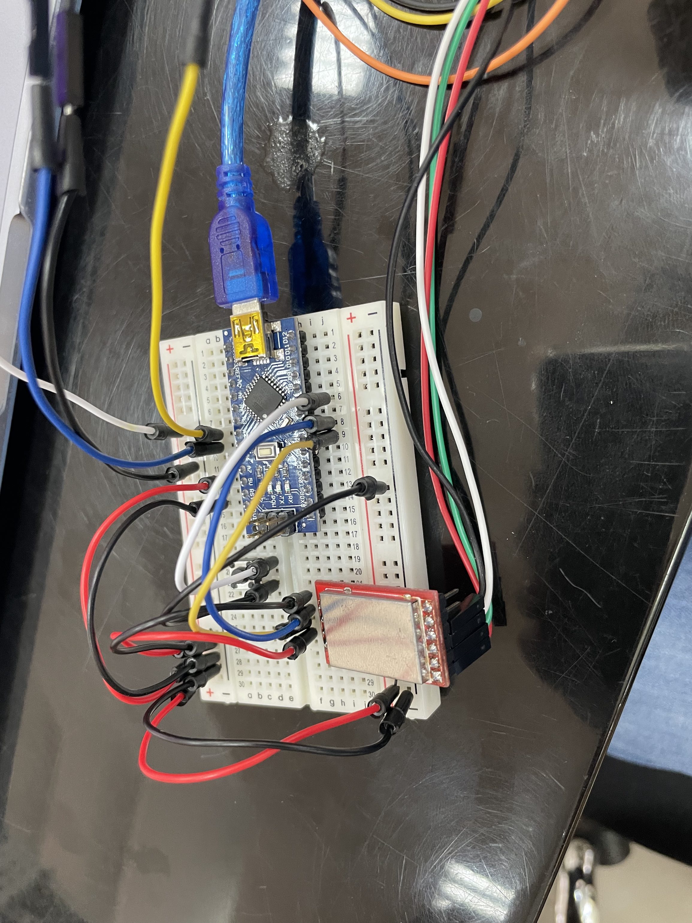
After using this type of load cell same issue observed. To avoid this issue we tried to use different library and different amplifier with noise reduction shield. New amplifier shown in image below.
The library used is HX711 which is brought form Github website.
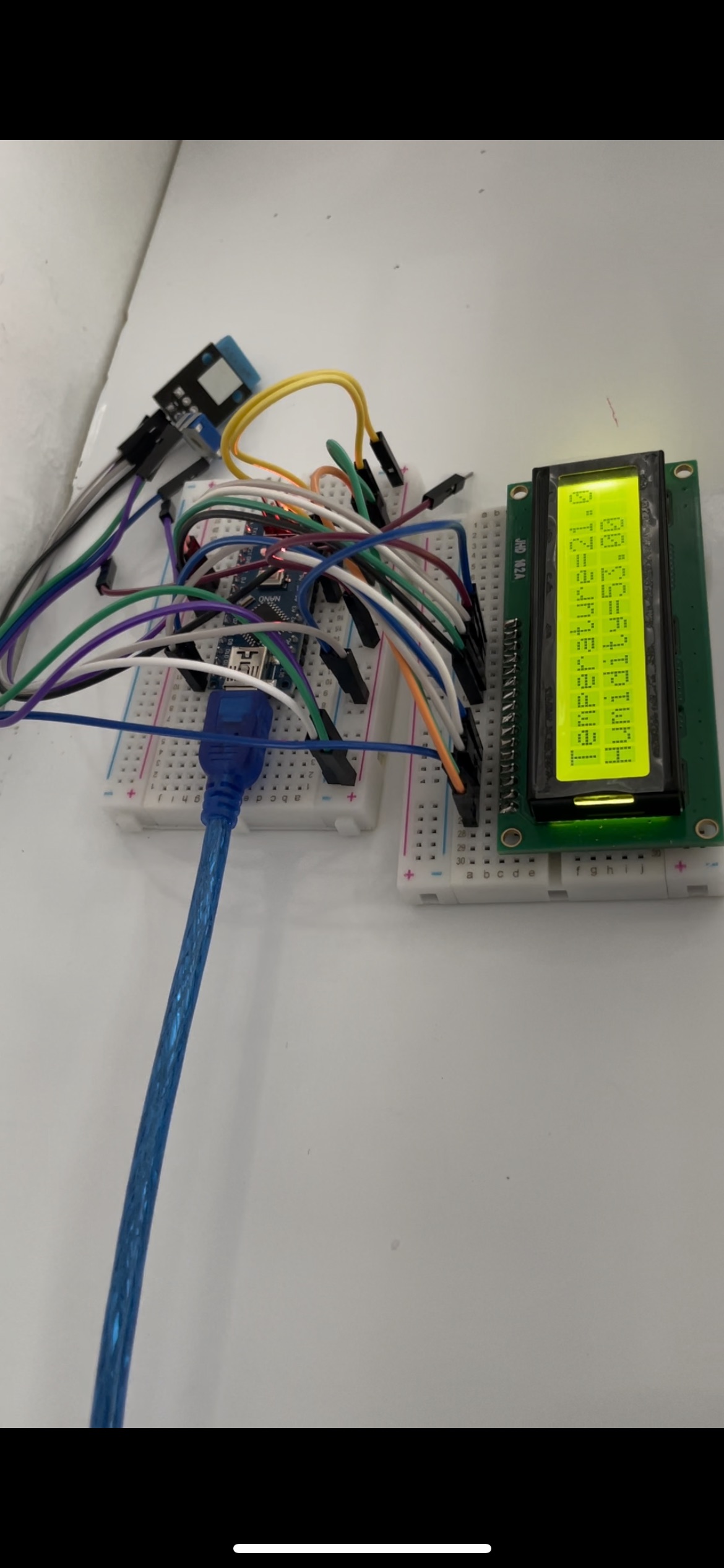
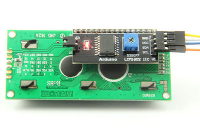
I2C module is used instead of direct wiring to lcd. In this case 4 wires only required instead of 12-16 wires which simplifies the circuit and reduce chances for mistakes to occur. I2C module is attached directly to lcd. Two pins are for power supply. Two pins are SDA and SCL. SDA which serial data and SCL is the clock pin.

Final Code
Load cell, humidity and temperature are viewed in the lcd screen using this code. Also, calibration function for 100 g is added. Read comments in the code for further explanation.
//==========================================================
// Definitions
//==========================================================
// btn is the button which is attached to digital pin 7 and the ground. This button is used to process calibration step by step.
#define btn_pin 7
#define start_btn pinMode(btn_pin, INPUT_PULLUP)
#define read_btn !digitalRead(btn_pin)
#define btn_wait while(read_btn == 0)
{ }
#include <dht.h>
dht DHT;
#define DHT11_PIN A1
//-----------------------------------
// LoadCell HX711 Section
//-----------------------------------
#include <HX711.h>
#include <EEPROM.h>
#define HX711_DAT_PIN 4
#define HX711_CLK_PIN 5
HX711 scale;
const int calVal_eepromAdress = 0;
unsigned long t = 0;
//-----------------------------------
// LCD Section
//-----------------------------------
#include <Wire.h>
#include <LiquidCrystal_I2C.h>
LiquidCrystal_I2C lcd(0x27, 16, 2); // set theLCD address to 0x27 for a 16 chars and 2 line display
//==========================================================
// Arduino Hardware Prepare
//==========================================================
void setup()
{
// Serial Monitor
Serial.begin(38400);
// Starting The Button
start_btn;
// Starting The LCD
lcd.init();
lcd.init();
lcd.backlight();
// Display Welcome Message
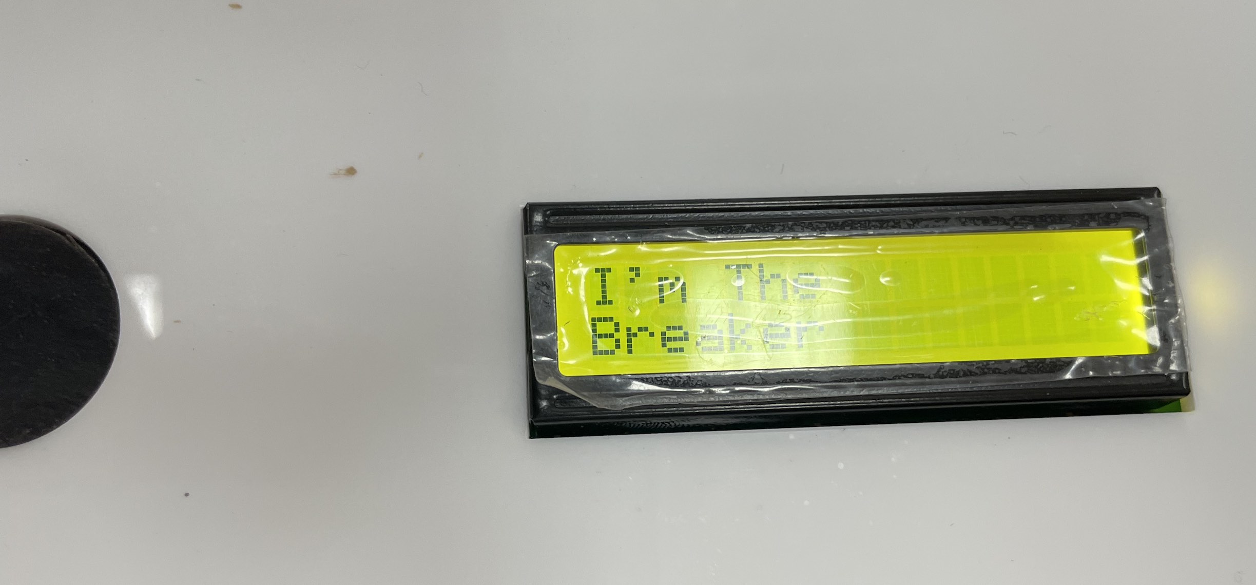
lcd_write("I'm The", "Breaker");
for(int i=0; i<3; i++) {
lcd_off();
delay(1000);
lcd_on();
delay(1000);
}
// While Button Not Press
while(1) {
if(read_btn) break;
}
//lcd.clear();
//lcd_off();
// Starting The Load Cell
scale.begin(HX711_DAT_PIN, HX711_CLK_PIN);
// Calibrate Scale
calibrate();
}
//==========================================================
// Main Program Loop
//==========================================================
void loop()
{
int chk = DHT.read11(DHT11_PIN);
long reading = scale.get_units(10);
//Serial.print("HX711 reading: ");
//Serial.println(reading);
//lcd edit
lcd_write("Weight: " + String(reading) + "g", "Temp=" + String(DHT.temperature) + "Hum=" + String(DHT.humidity));
delay(2000);
if(Serial.available()) {
String x = Serial.readStringUntil('\n');
x.trim();
if(x == 't') {
scale.tare();
}
}
}
//==========================================================
// For Writing On LCD Display
//==========================================================
void lcd_write(String line1, String line2) {
lcd.clear();
lcd.setCursor(0, 0);
lcd.print(line1);
lcd.setCursor(0, 1);
lcd.print(line2);
}
void lcd_on() {
lcd.backlight();
}
void lcd_off() {
lcd.noBacklight();
}
//==========================================================
// LoadCell Funtions
//==========================================================
void calibrate() {
// 1st Step Set Scale
scale.set_scale();
delay(100);
// Call Tare
scale.tare();
delay(100);
// Wait For Button Action
while(read_btn == 0) {
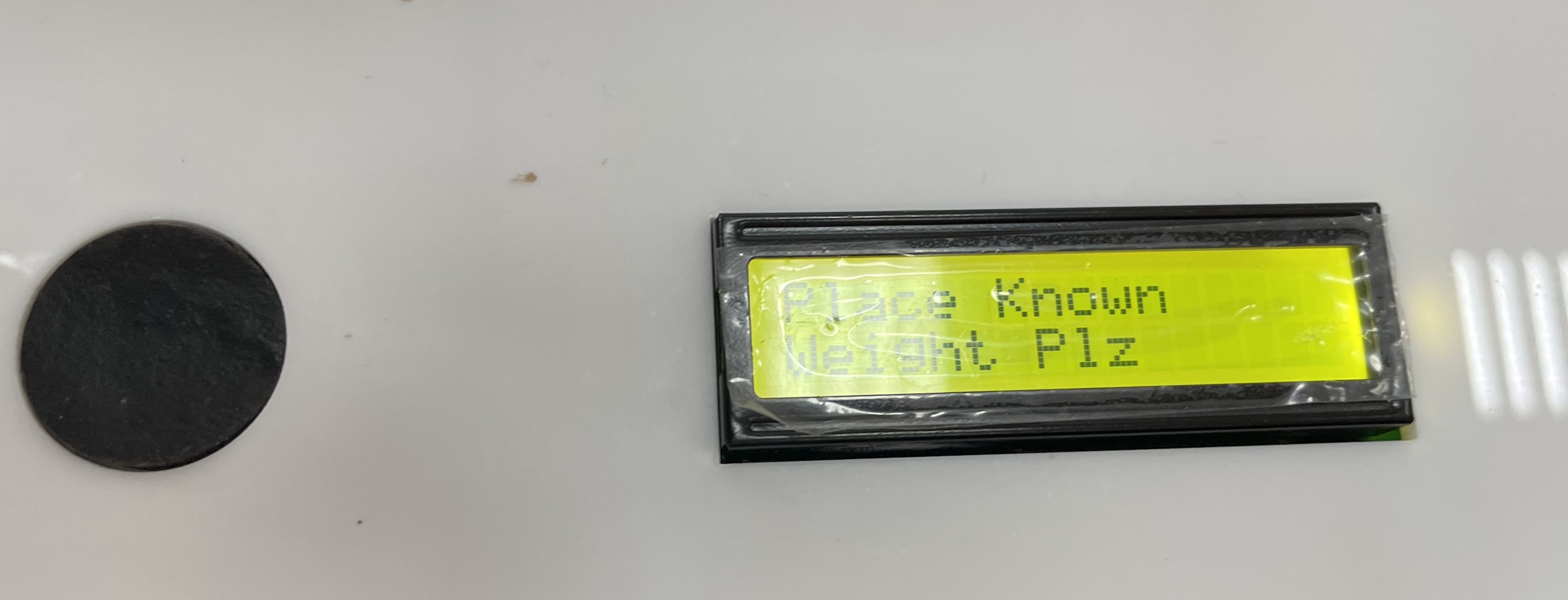
lcd_write("Place Known", "Weight Plz");
delay(1500);
lcd_write("Then Press", "The Button");
delay(1500);
}
// Reading Weight
lcd_write("Please Wait", "Reading Weight");
double val = scale.get_units(1000);
lcd_write("The Value :", String(val, 2));
// Deviding The Value
double result = val/100;
scale.set_scale(result);
// Display Done Message
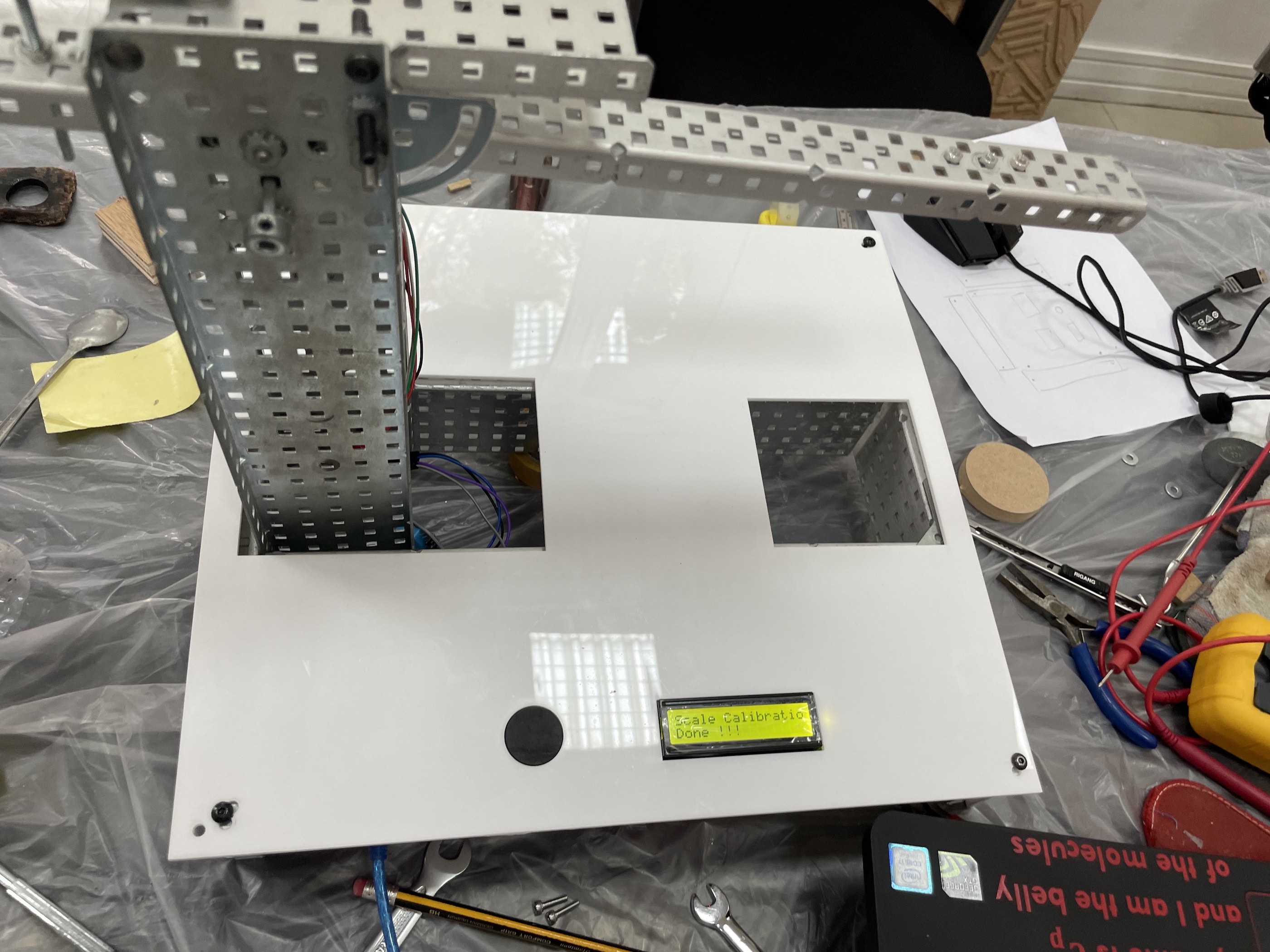
lcd_write("Scale Calibration", "Done !!!");
btn_wait;
delay(1000);
scale.tare();
}
Results
After changing the amplifier, load cell and the library (from hx711 adc to hx711), results are reasonable. Device readings are very accurate.
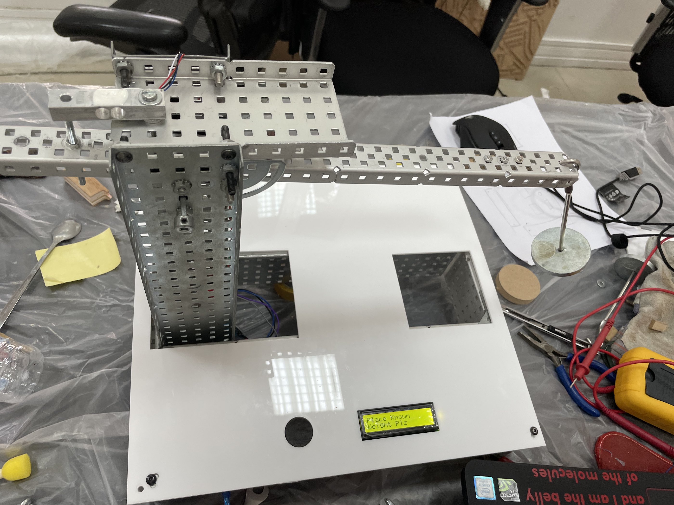
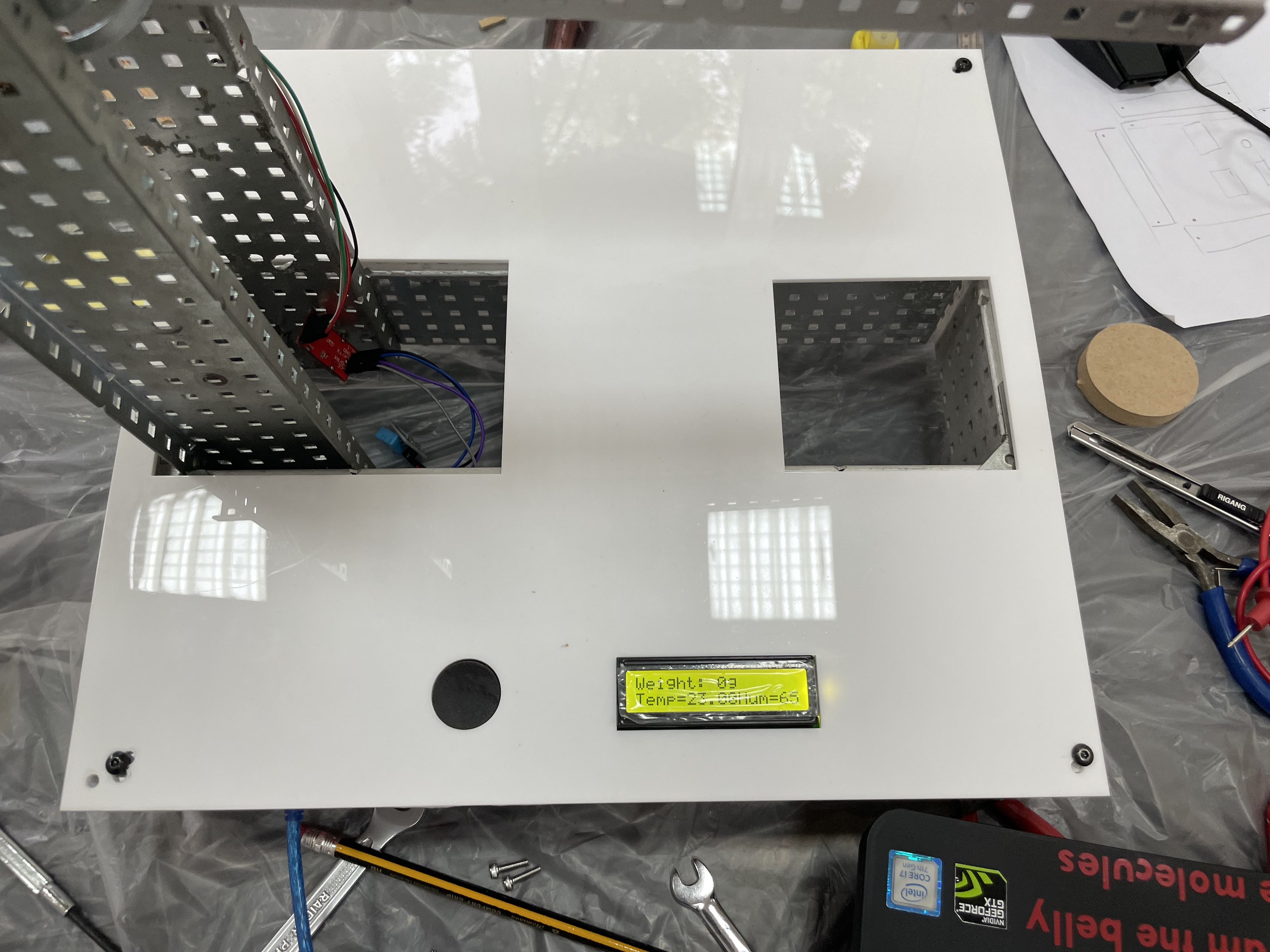
The following pictures shows how device works
First I’m the breaker welcome message appear.
Then when you press the button, you will be asked to place known weight. The load cell is programmed to 100 g calibration weight. This can be changed through Arduino code.
After this you will see scale calibration done! message.
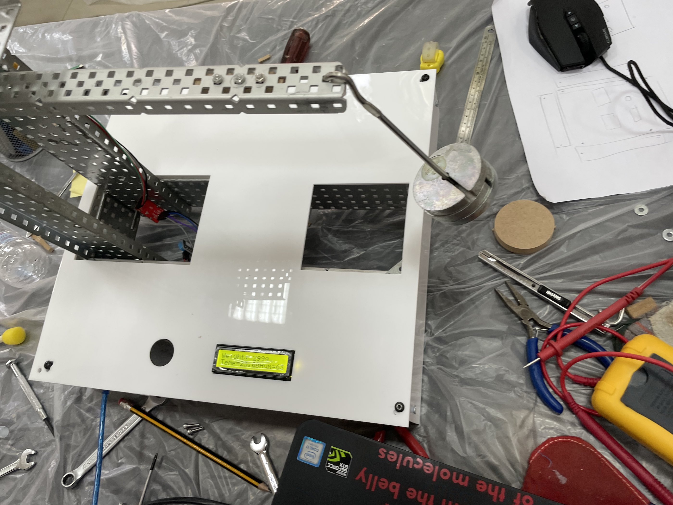
Now remove weight and press the button. Make sure to remove the weight before pressing the button because taring will occur to make weight zero.
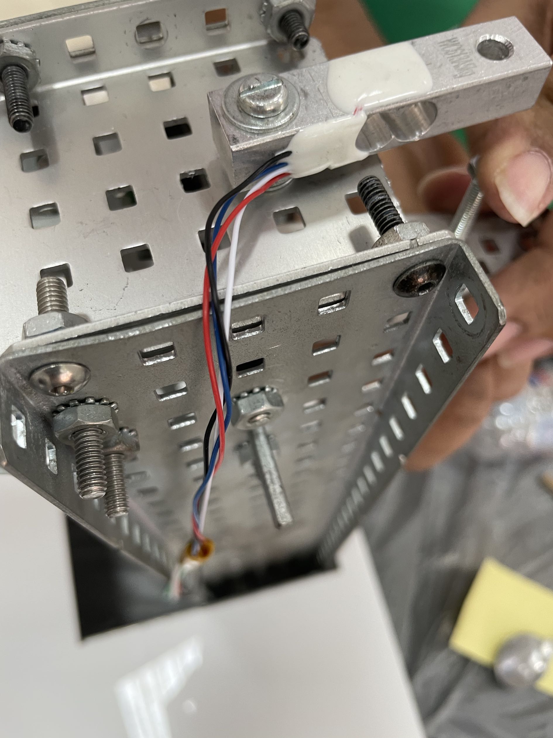
The total hanger weight is 296.5 g according to sensitive weight balance. The value observed is very close which proves that load cell is working probably.
Design Idea
Assembling and Soldering
References
50kg Load Cells with HX711 and Arduino. 4x, 2x, 1x Diagrams