3. Computer controlled cutting
Design and cutting
Hello everyone, the task for the third week in Fab Academy was to model a piece of furniture on our preferred 3D design application, and cut it using the CNC machine.
The design I chose was inspired by this book shelf that I discovered on Pinterest
But I decided to make it smaller, 75 cm long, and 50 cm wide,11 mm thick (the thickness of the sheet provided), with three shelves, without the back piece that I am presuming works as a support for the shelves to make them endure large weights.
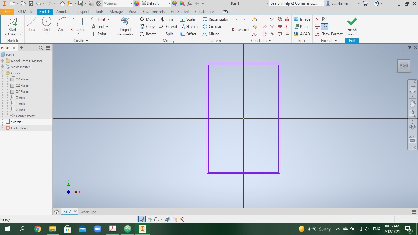
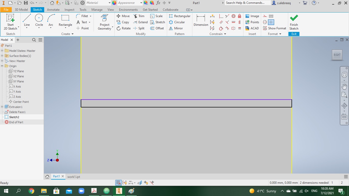
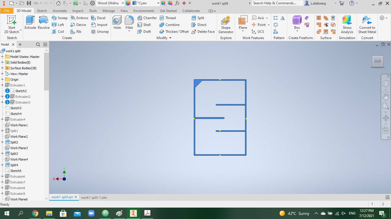
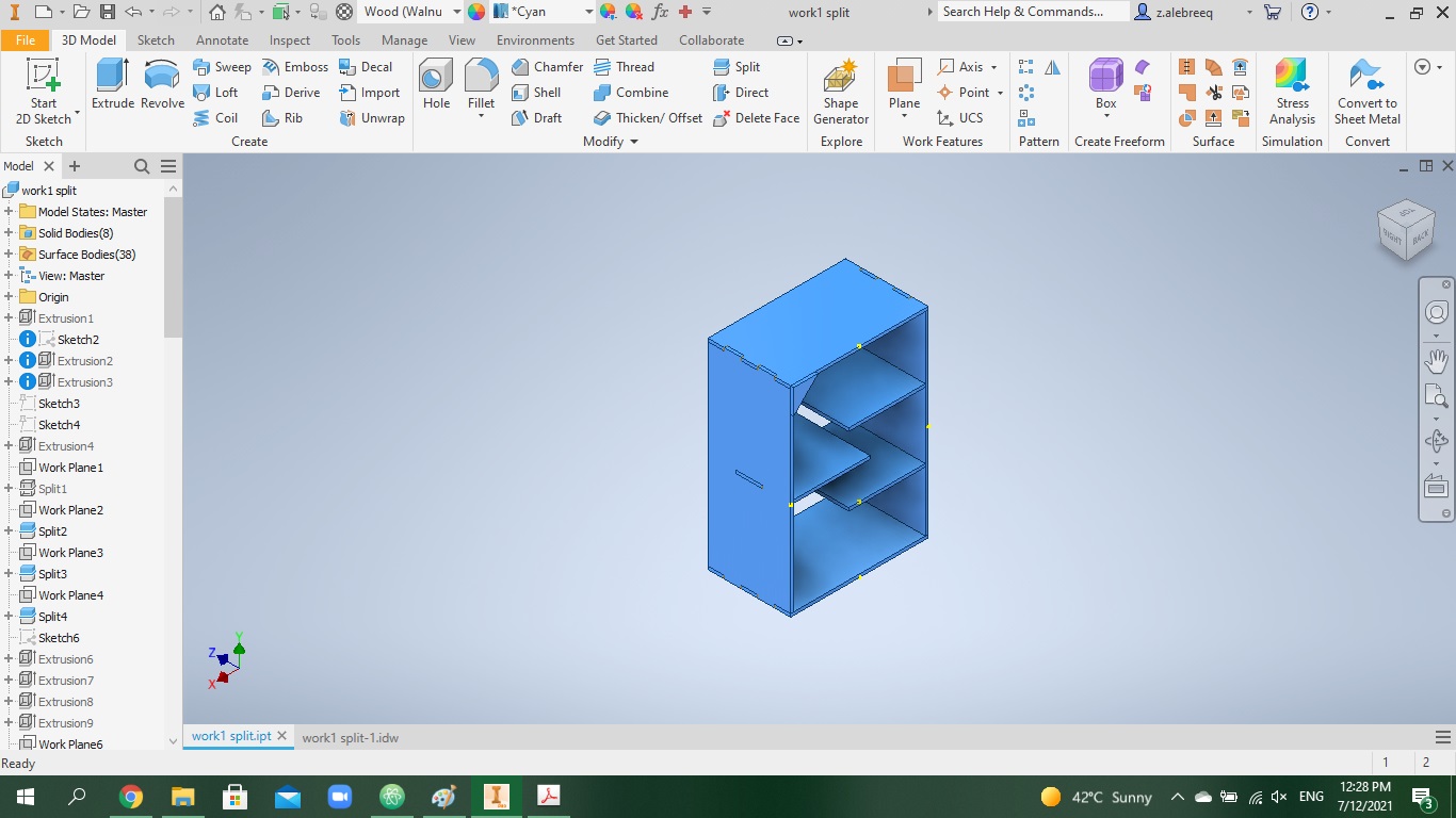
I started working on the design on Fusion 360, however I had some trouble with the program. My friend Noor in the academy recommended Autodesk Inventor to me. I downloaded it and began working on it, I found it easy to use and it has various tools and functions that are similar to Fusion 360. First, I started off by drawing a rectangle with the dimensions 75x50 cm, after that I drew another rectangle inside it, it was 11 mm far from the sides of the first rectangle, which resembles the thickness of the wood (the material of the sheet provided by Fab Academy).
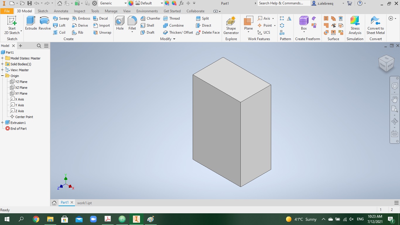
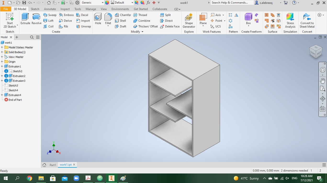
Following that, I used the extrude tool (300 mm) to turn the 2D sketch into a 3D model,
I deleted the faces in the front and back to make it hollow,
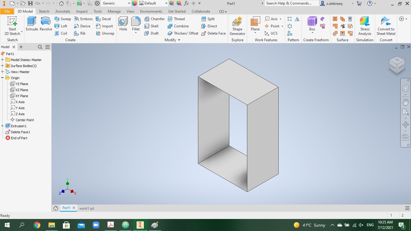
then I did the same procedure to model the inside shelves.
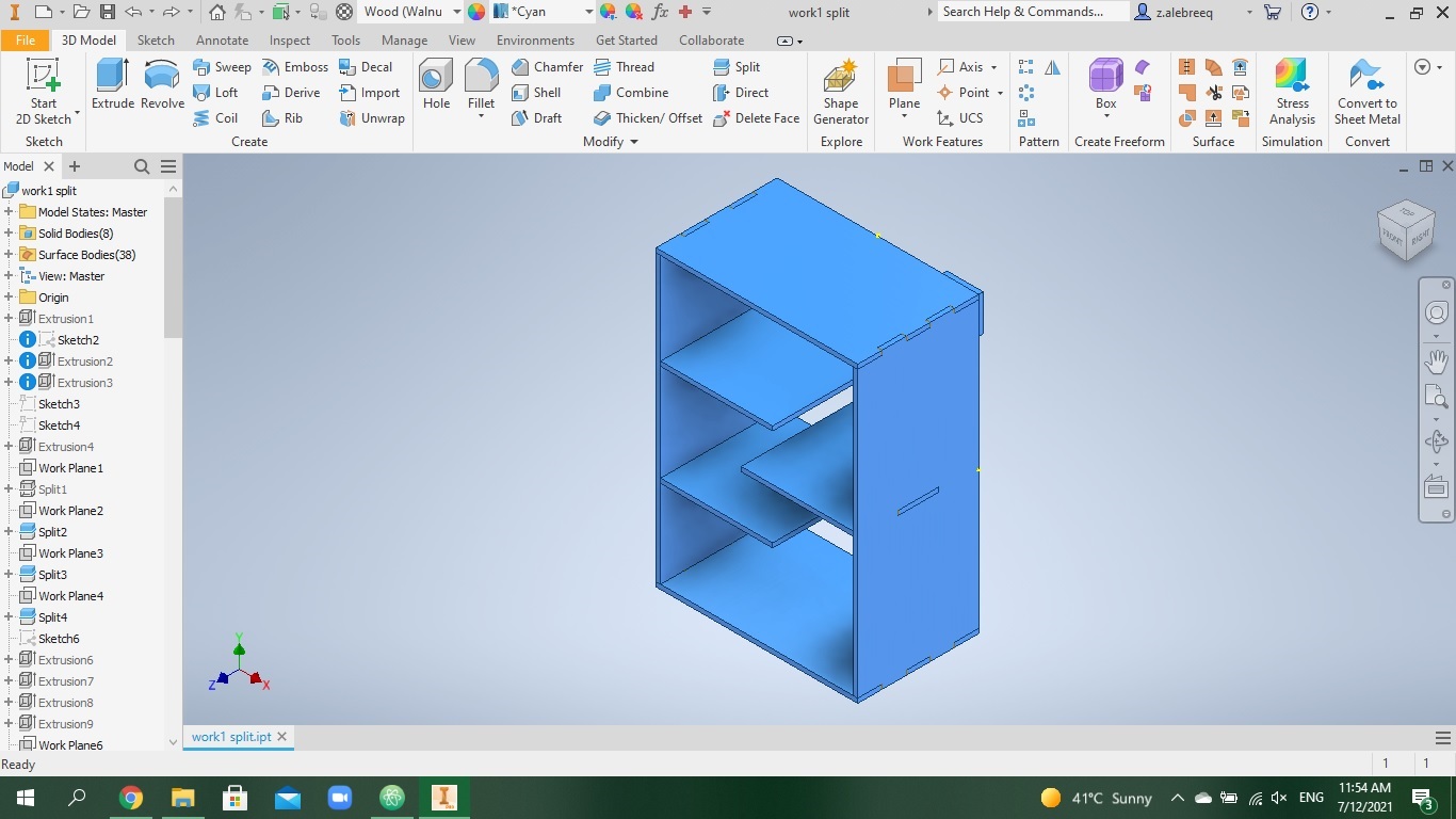
This is when the process started getting tricky. The model I built was basically one solid. CNC machine cannot cut such thing. I had to split the solid into pieces, to make each piece of the furniture (i.e. top shelf). I looked on youtube for a way to split the solid, I figured it out and did it. Then, I had to make joints to connect the pieces together. This was the most tedious step. I drew rectangles on the pieces (main bodies) representing the joints, used extrude cut, then moved the tool bodies in a way to connect to their main body, after that I used the combine cut function to bring them all together.
It might sound simple, but it definitely was not, as the program I am using is new to me, in fact the whole modeling of furniture is a new concept to me. Then I used the tool thickness on the sides of the joints to make sure the parts can be connected together, the tolerance I added was 0.12 mm When I completed the 3D model, I made a pdf containing 2D sketches of each view of my model. Since Vcarve (the software connected to cnc machine) only accepts 2D sketches and it converts them to a format that the machine can understand and cut. I did that by creating a drawing file on inventor, I changed the scale to 1:1
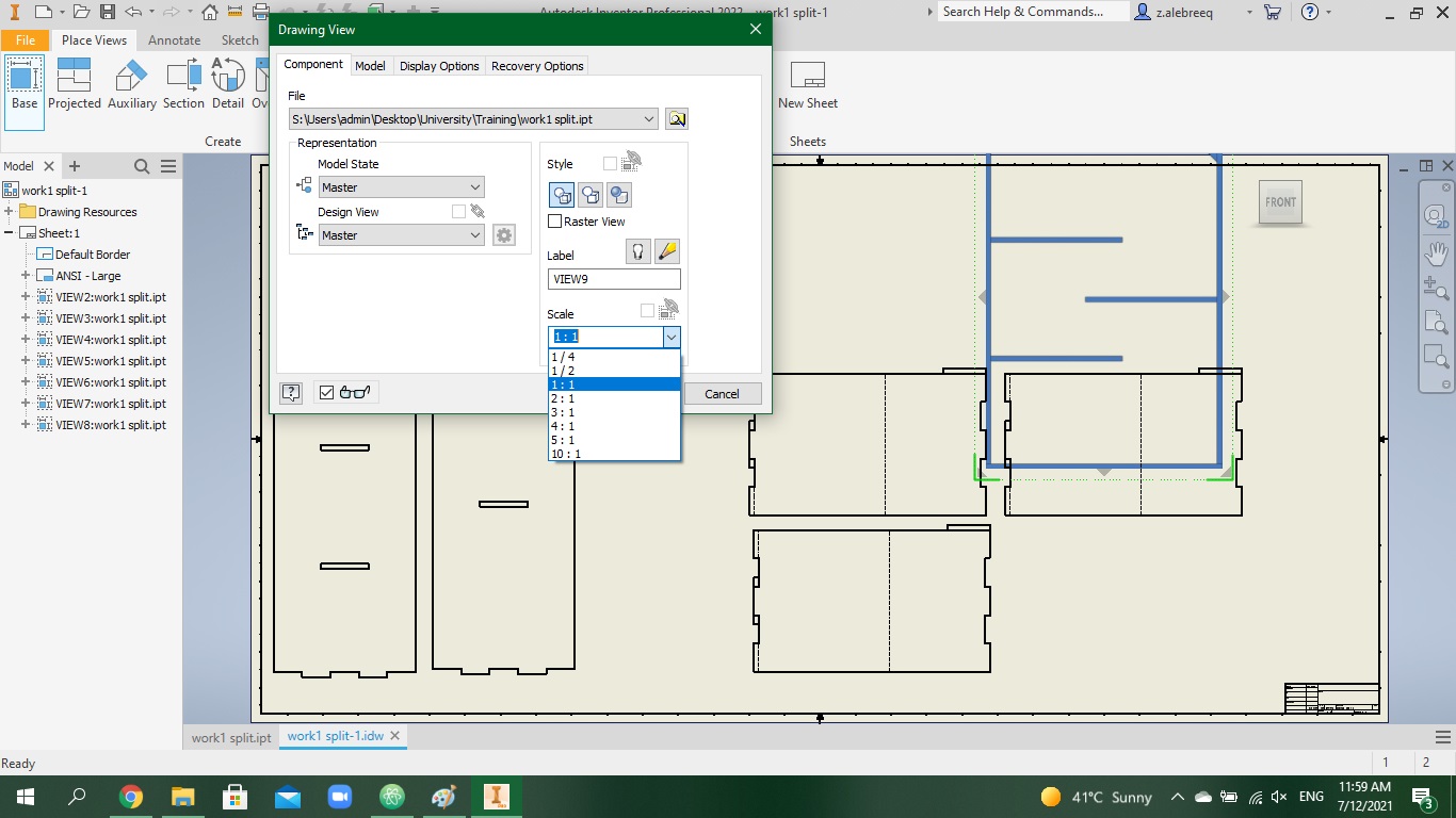
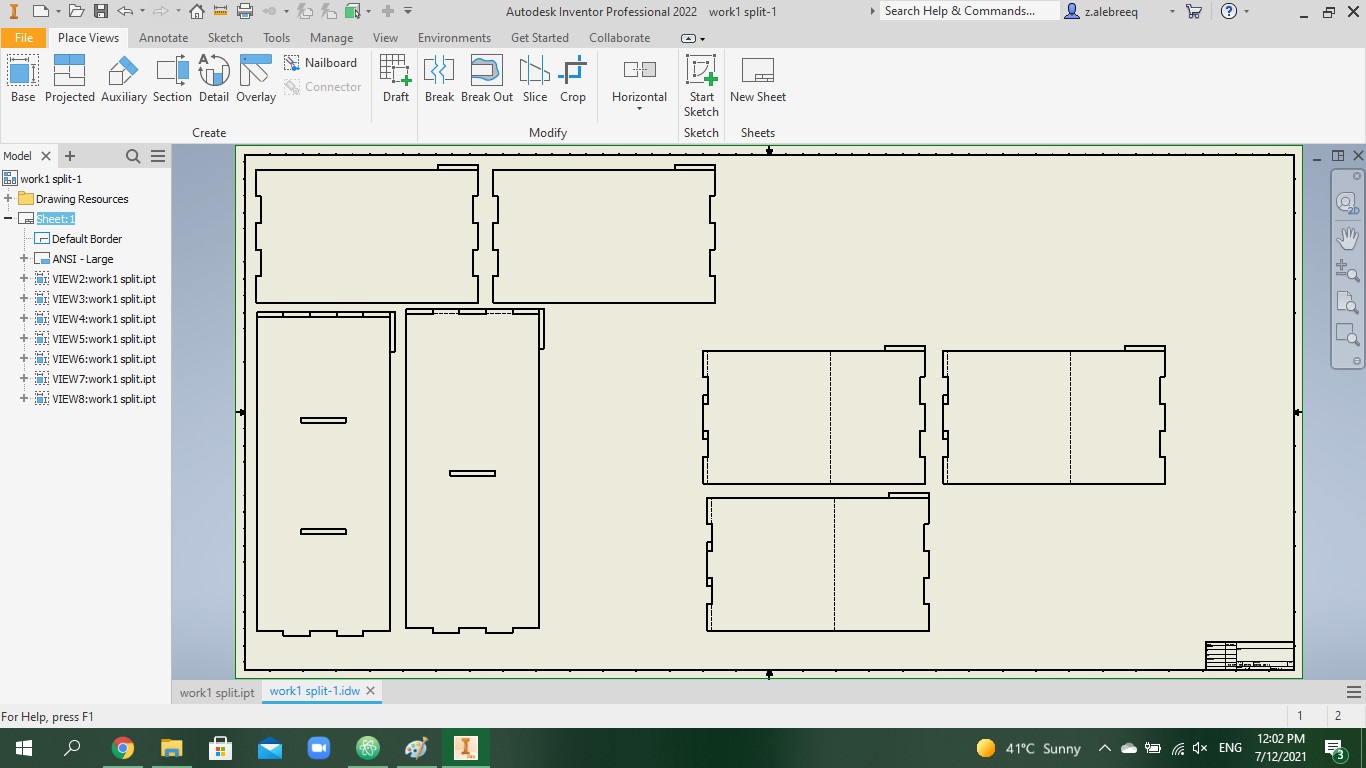
After that I changed the sheet dimensions to 1200x2400
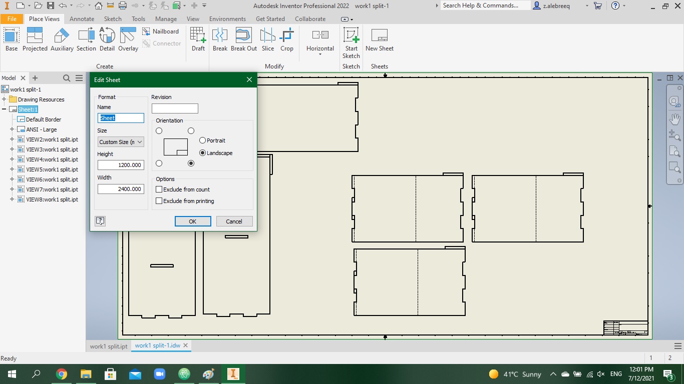
I hid all the solids by unticking the visibility of all the solids, except the one I want to make a 2D sketch of, I did this multiple times to add all the parts to the sheet.
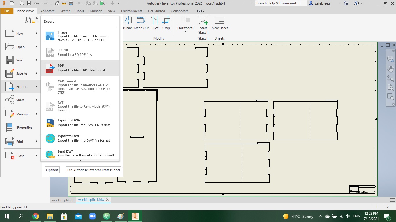
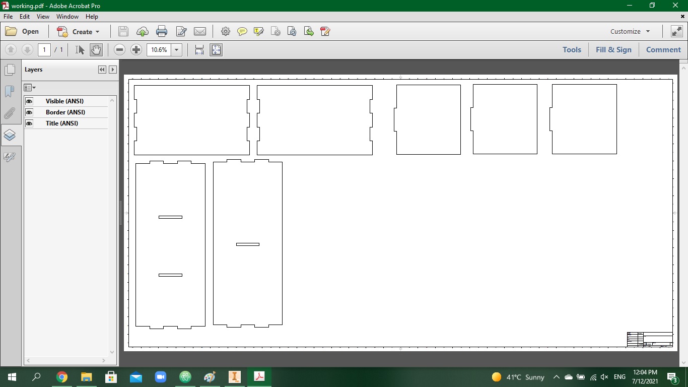
Then I exported the file to pdf format, which is a format that Vcarve can understand
When I was done with the design completely, we went to the cnc room, there was a laptop connected to the cnc machine containing Vcarve software
This is what Vcarve looks like when you open it
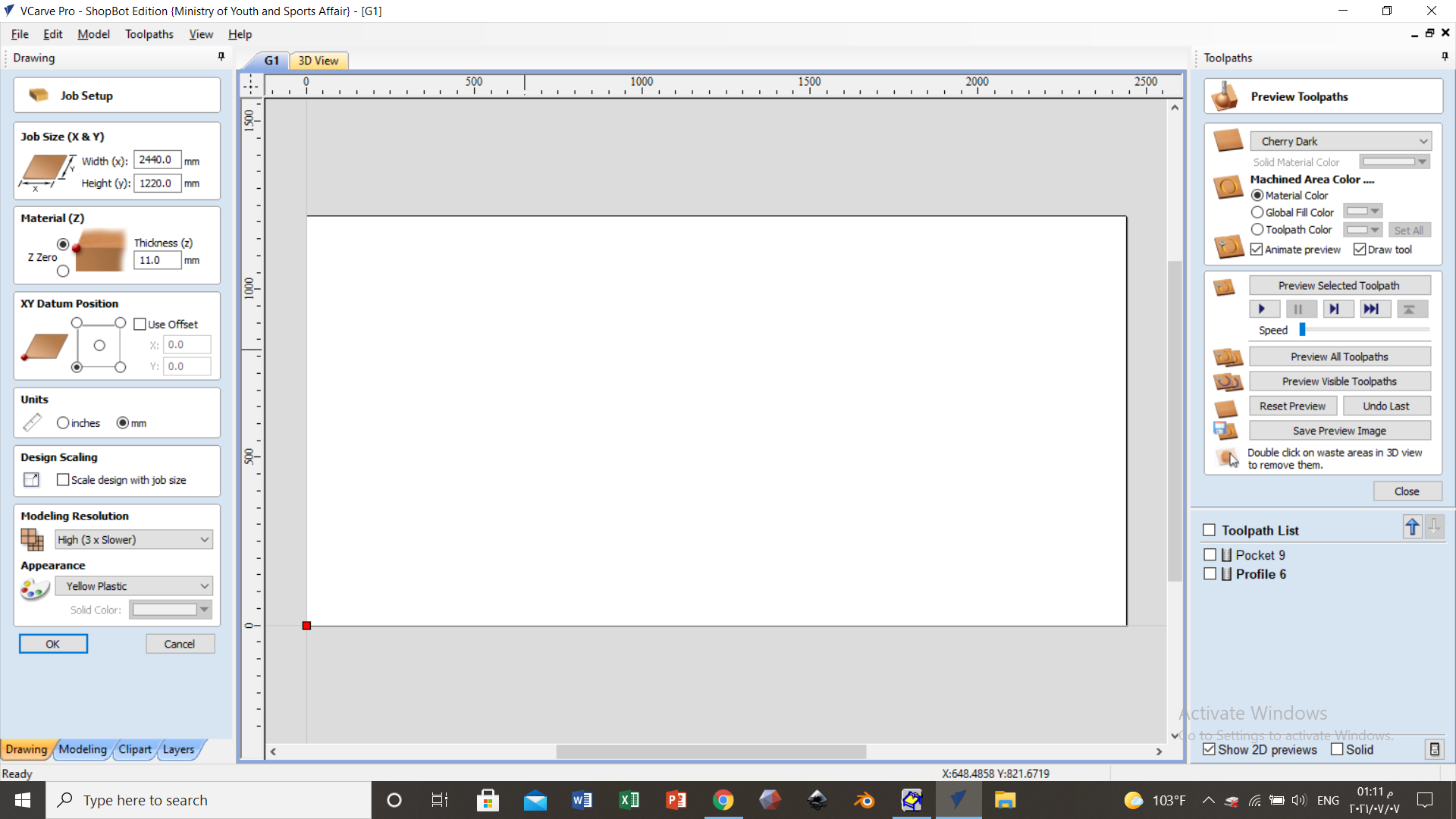
We imported the sheets and added all the parts that can fit from other people’s designs to minimize waste Below the wood sheet, there was another sheet because the setting of the drill bit, how low it gets inside when carving the material was above 11 mm which is the thickness of the sheet because we want to make sure the drill bit is getting all the way in, and the other sheet is to protect the machine setup from getting damaged

we did dogbone fillets for the inside edges, because the drill bit in the machine is too big it cannot cut the edges properly After that we executed the cutting, while the machine is working, you cannot do anything else on the laptop, the only thing you can do is wait for the cutting to be completed, or you can click on the red button connected to the laptop to abort the cutting process

After doing the cutting and manually removing each solid from the sheet, we had to scrape the tabs and file the boarders using a silicon carbide sheet and a scraping metal tool
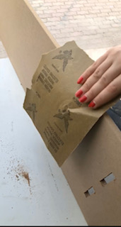
I assembled the parts
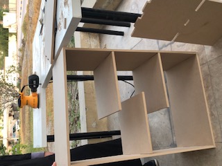
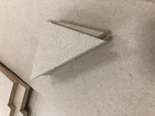
Even though I designed the tolerance for all the joints to be the same dimension, the top and bottom shelf did not fit properly, the joints were a bit wide, the whole assembly was not stable for that reason One of my supervisors, Abdulla, who witnessed my struggle while assembling, recommended that I make 4 support triangles to put in all the corners I did it on inventor
This is what the triangles looked like after cutting
Another thing I wanna mention is that PPE must be worn inside the cnc room, we cannot wear wide flowy clothes and go near the machine because our clothes could get stuck inside it, we were given safety goggles to wear inside the room.
More details are provided in the group assignment linked below
Dog bone fillets
Regular fillets are used to reduce the sharpness of corners. The corners can be modified with either a chamfer or curve.
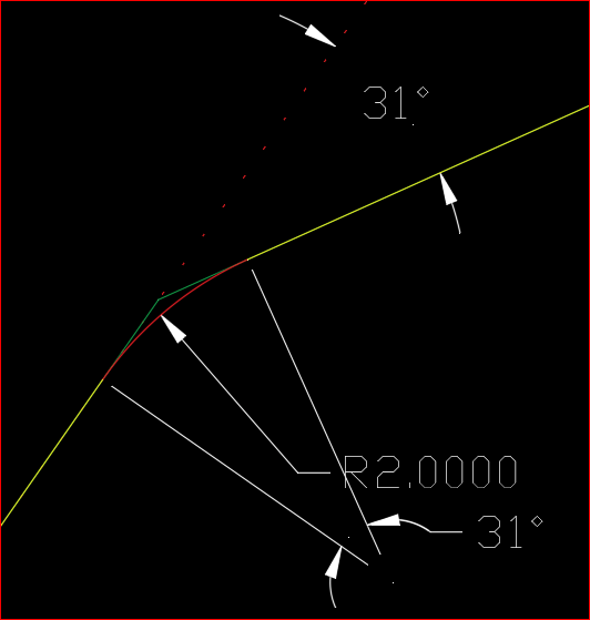
A regular fillet creates an arc that is always inside to the edges.
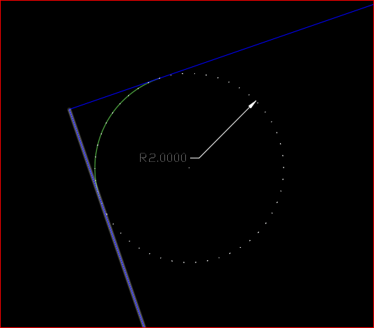
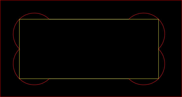
In the process of CNC milling, there are cases where an outward curve may be required. The inner corners can never be sharper than the diameter of the cutting tool. This is because the router bits are round. It is not possible to get orthogonal corners at perfect right angles when cutting out the sheet materials, therefore these corners will be rounded inwards, using dog bone fillets. The dog bone fillet is different from a regular fillet, because it creates a circular arc that is outside of the edges. The point of intersection for both edges is actually the mid-point of the arc.
If dog bone fillets are created at each corner of a rectangular block, it looks like an actual dog bone.