8. Molding and casting
The task for this week was to do molding and casting.
The first step was to design a 3D object of the dimensions 80 x 40 x 10 mm.
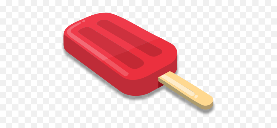
I decided to make a popsicle, on Fusion360
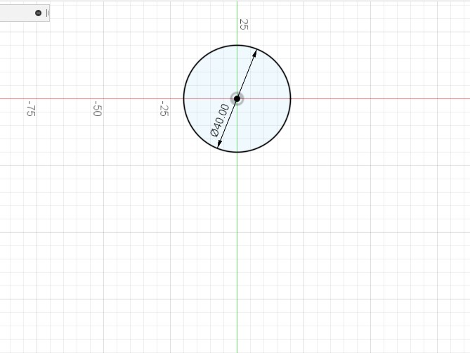
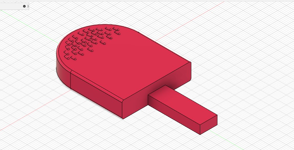
First I drew a circle with a 40 mm diameter
Then I drew a rectangle where the top side is at the center of the circle and within the circle’s circumference
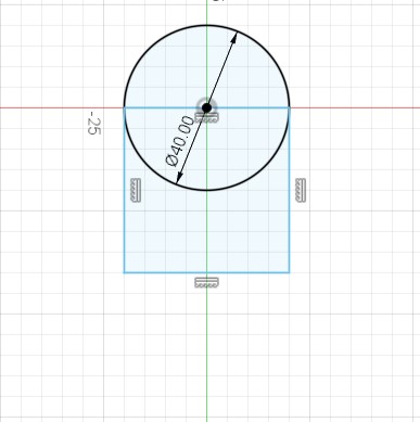
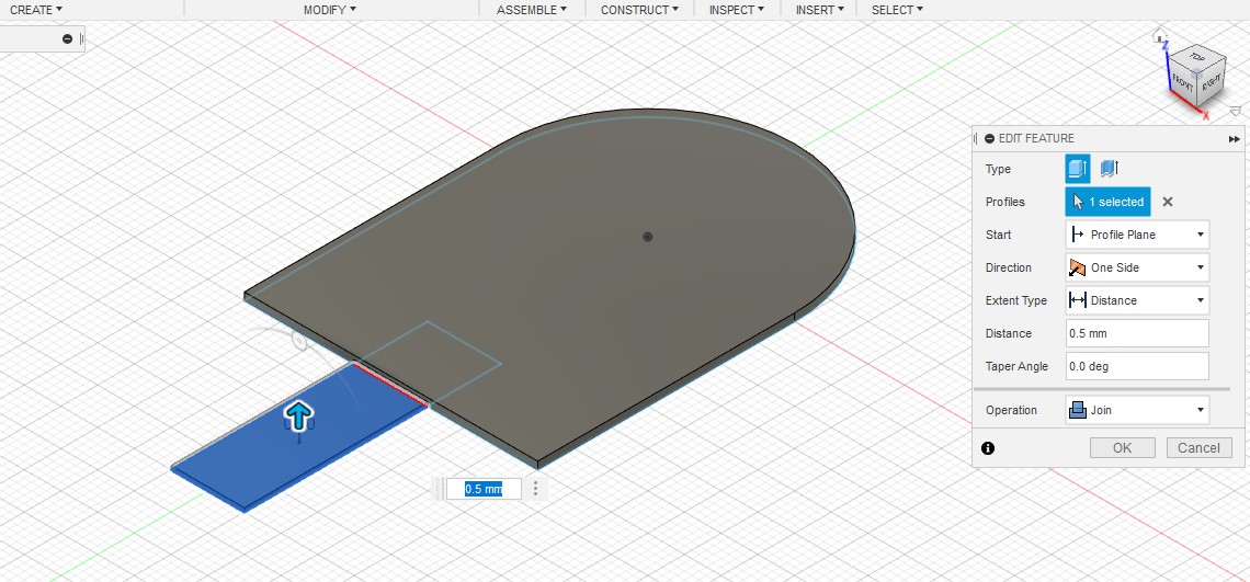
The third step was to draw another rectangle that will be the stick of the popsicle

I made the length of the circle and both rectangles combined to be 80 mm
Then, I made an extrusion of 1 mm for the surface of the ice cream part in the popsicle, this was a mistake, it should be 10 mm, I edited it later on
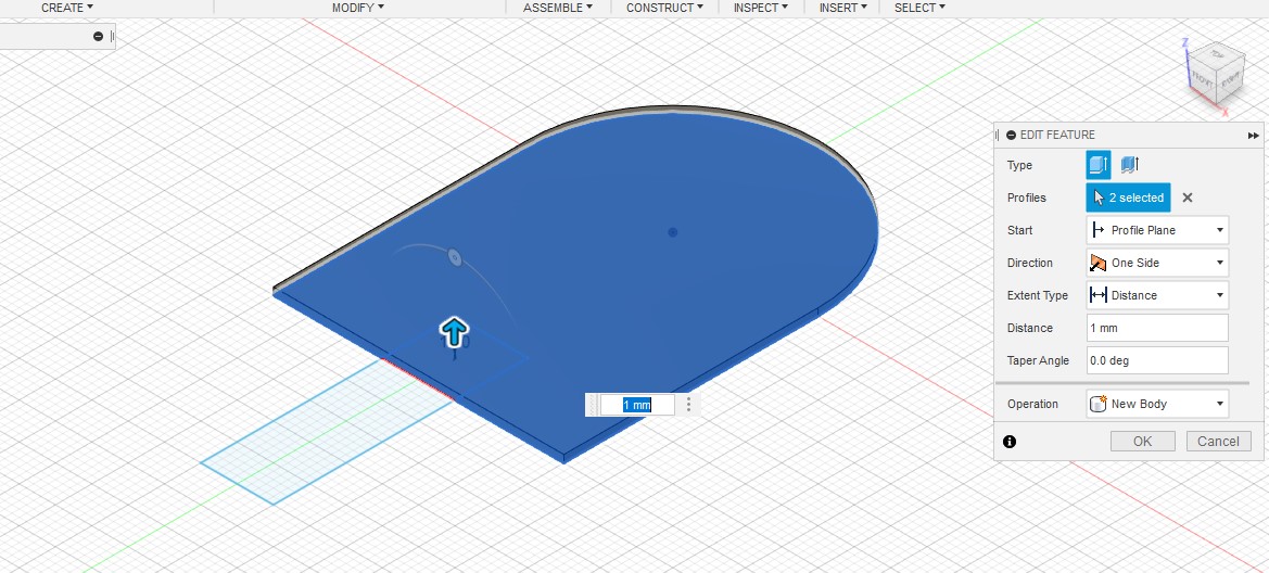
However, for the stick I extruded it to 0.5 mm only. As illustrated in the clipart below, the stick is attached to the center of the ice cream, there is a space above and below the stick, but the milling machine would not be able to cut it if there was an empty space in the bottom. The bottom part has to be completely flat. Therefore, I made the stick extrusion start at the same point as the ice cream, but end beneath it.
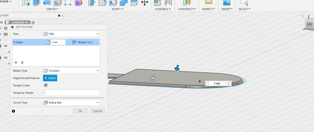
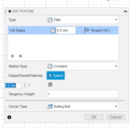
Following that, I made a fillet for the top extrusion, to make the corners round and smooth rather than sharp. The drill bit in the milling machine is round, it cannot cut sharp edges perfectly, so it is better to make the design curvy, and to make it look more realistic as well.
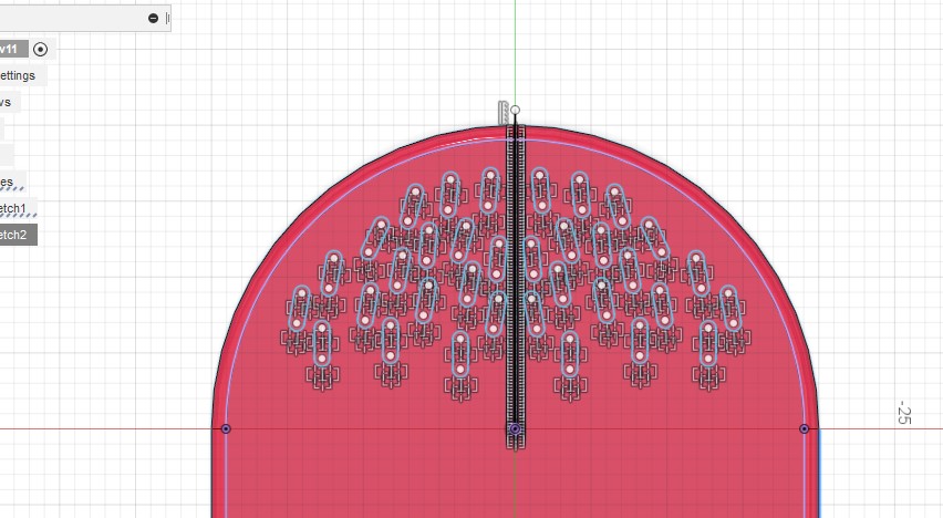
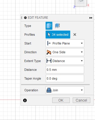
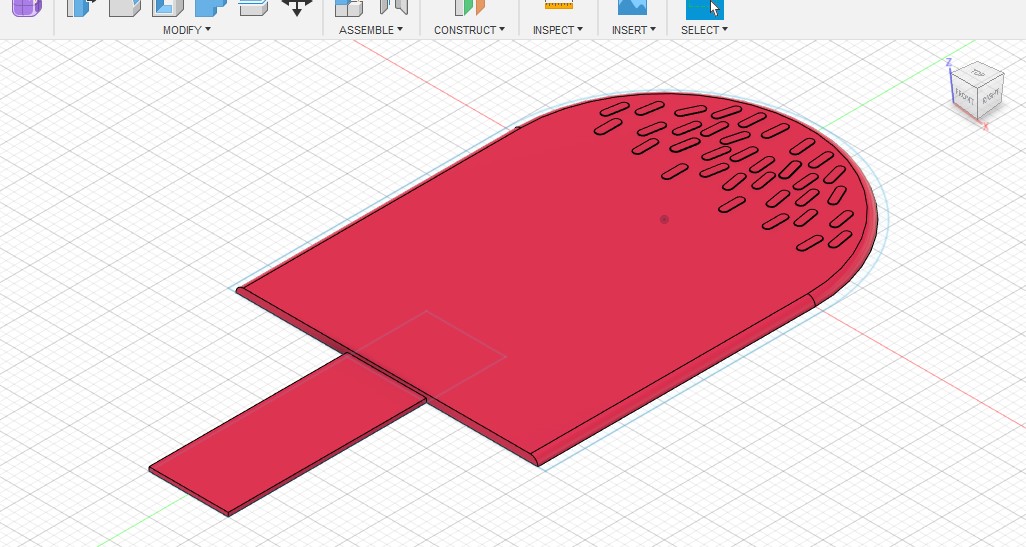
This is what it looked after the extrusions and fillet, I added sprinkles as well by drawing “slots” and extruding them and making fillets.
This is what it looked after the extrusions and fillets.
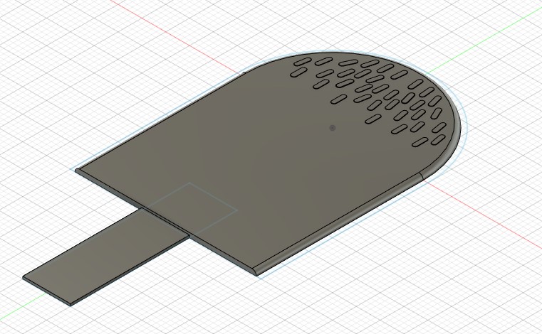
I changed the color of the object to pink
In the next step, I made it more proportional, by decreasing the length of the top rectangle, so there would be enough space to hold the stick
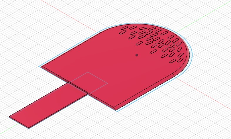
Finally, I realized the depth is wrong, it should be 10 mm, so I fixed it by simply clicking on edit feature and changing the extrusion dimension. This is the final design:
I exported the file to STL, which is the format that the program connected to the milling machine can understand.
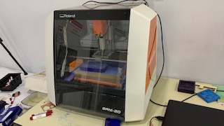
This is a picture of the milling machine, it is called Roland SRM-20, and it is connected to a program called SRP player which was designed exclusively for the machine.
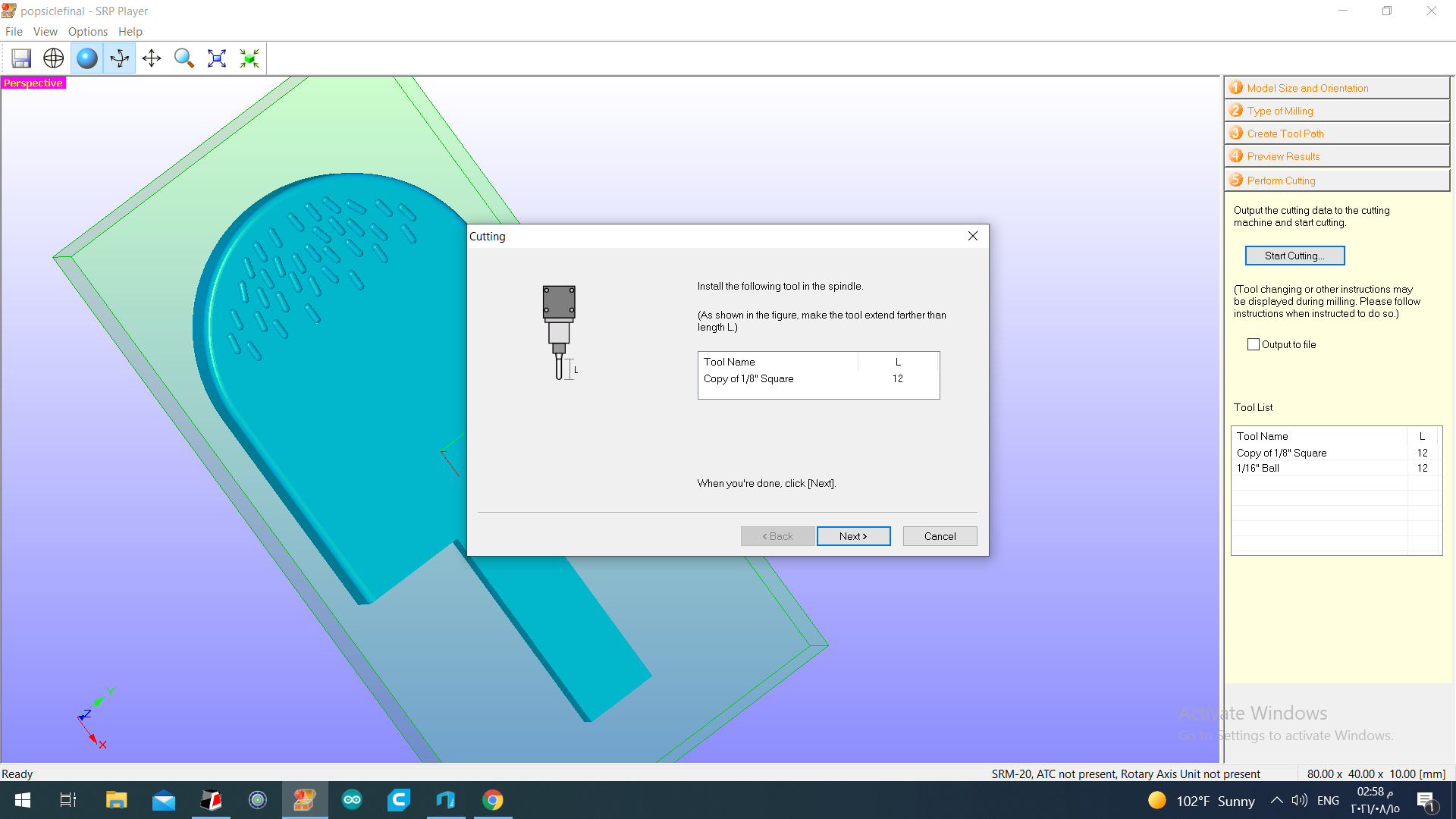
After I opened the program, I opened my STL file, first thing I did was click on Options>View Tools, I made sure the drill bits I wanted to use are already identified, which were 1/8 in. and 1/16 in.
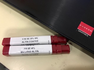
The large bit (1/8 in.) will be used in the roughing process, to make the big cuts. Whereas the small bit (1/16 in.) will be used to make the small details that require more precision such as the sprinkles.
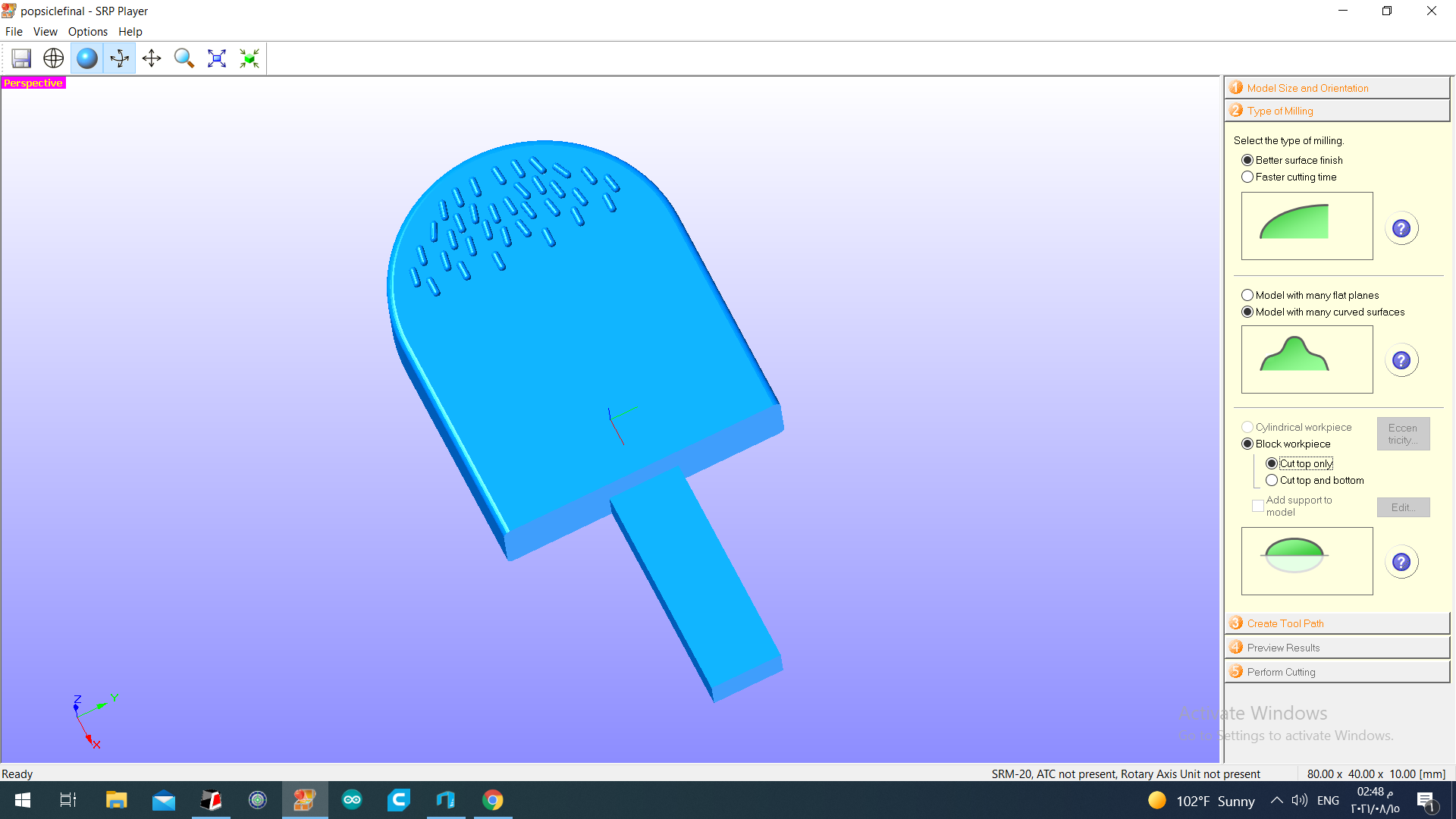
This is what the program looked like upon opening, the first step was to enter the model size and orientation, which was 80x40x10 mm.
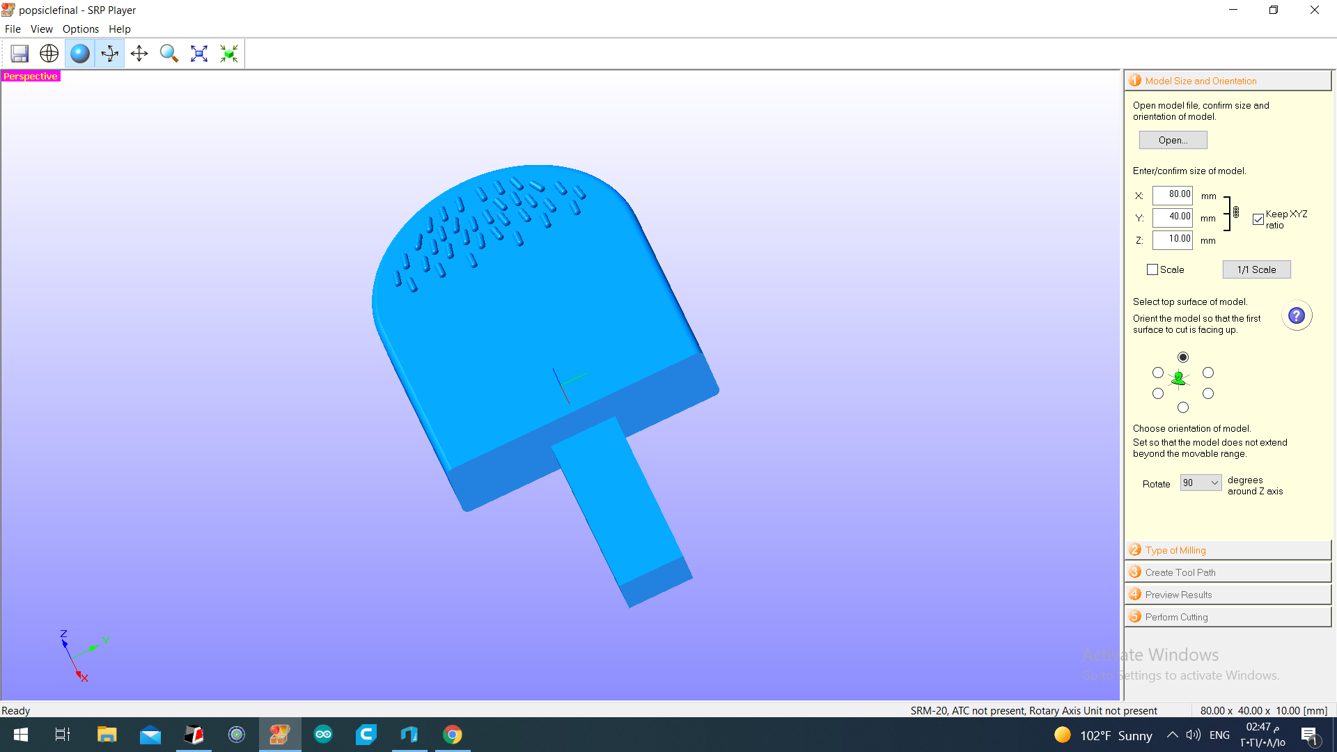
The second step was to select the type of milling. I was looking for decent surface finishing, so I selected better surface finishing. My design contained curves at the top, so I chose model with many curved surfaces. I wanted to cut the top part of the workpiece only, I did not want to cut it all the way down.
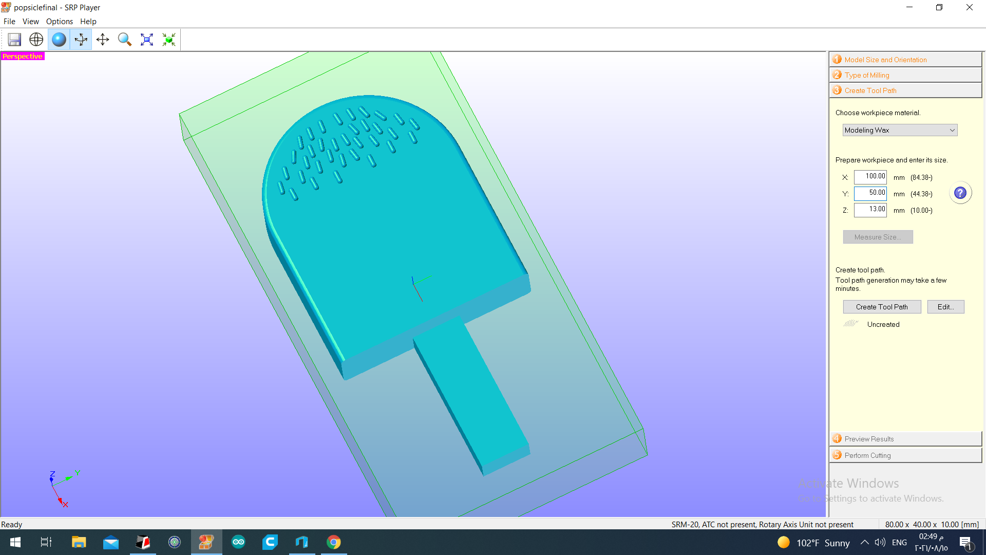
The third step was to enter the dimensions of the workpiece. The workpiece was a block of machinable wax, we indicated the center point of the piece with a pencil, we will put the drill bit exactly on the center of the workpiece later on. I measured the dimensions of the block, it was 100x50x13 mm.
Then I clicked on “edit”
I clicked on roughing>ball, I changed the drill bit size to 1/8 in.
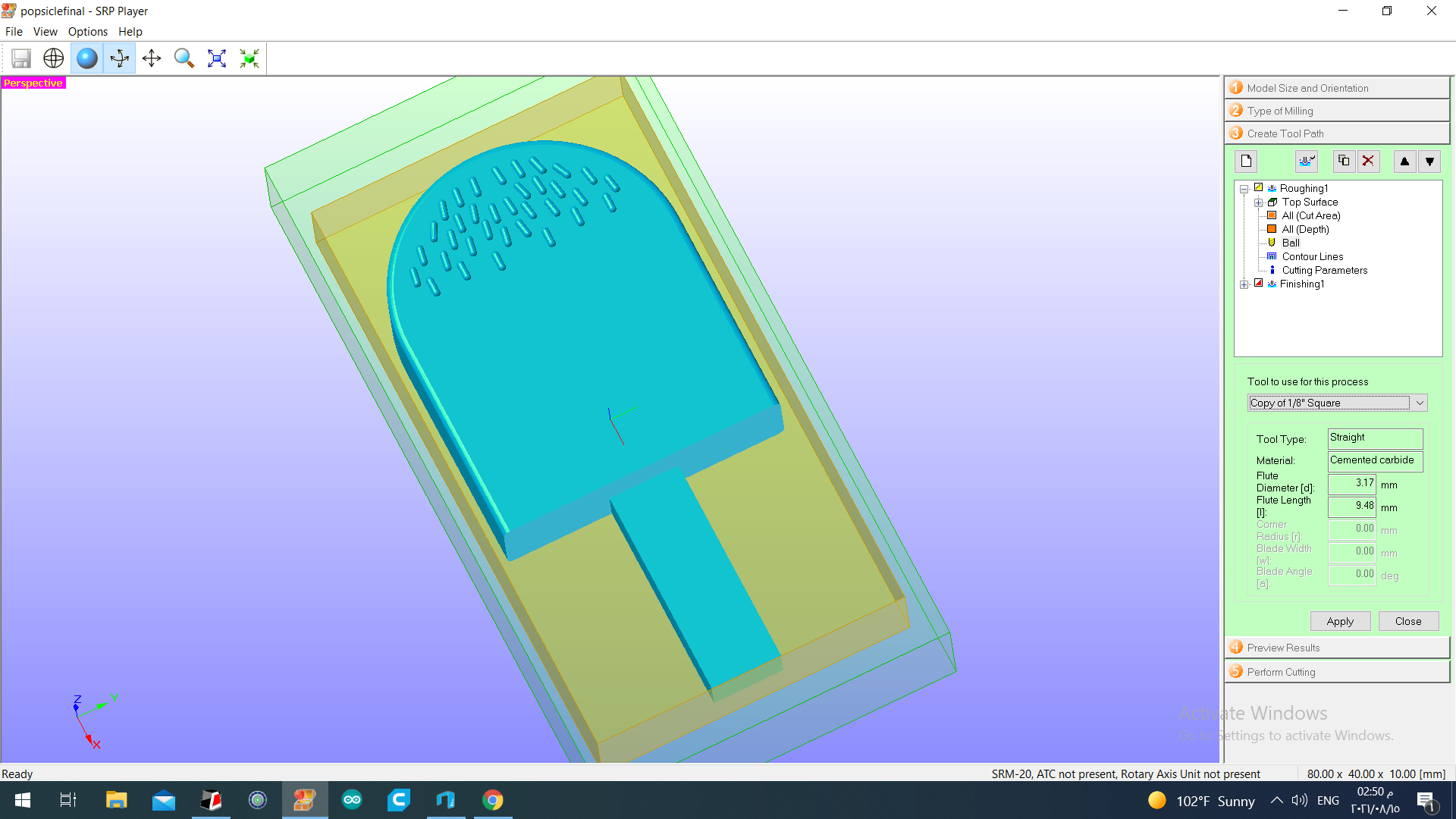
I clicked on finishing>ball, I changed the drill bit size to 1/16 in.
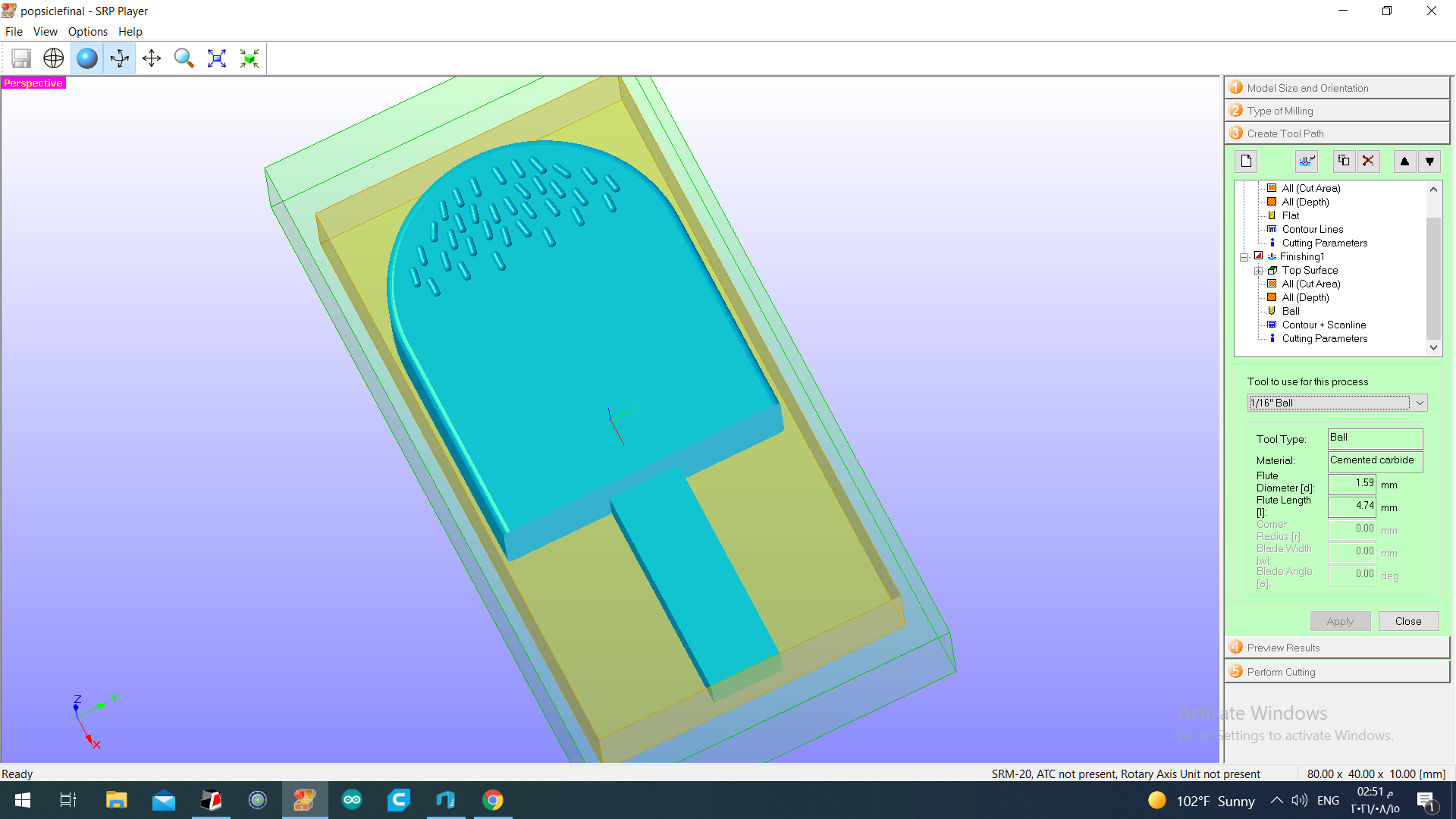
After that, I clicked on create tool path and proceeded to the next step.
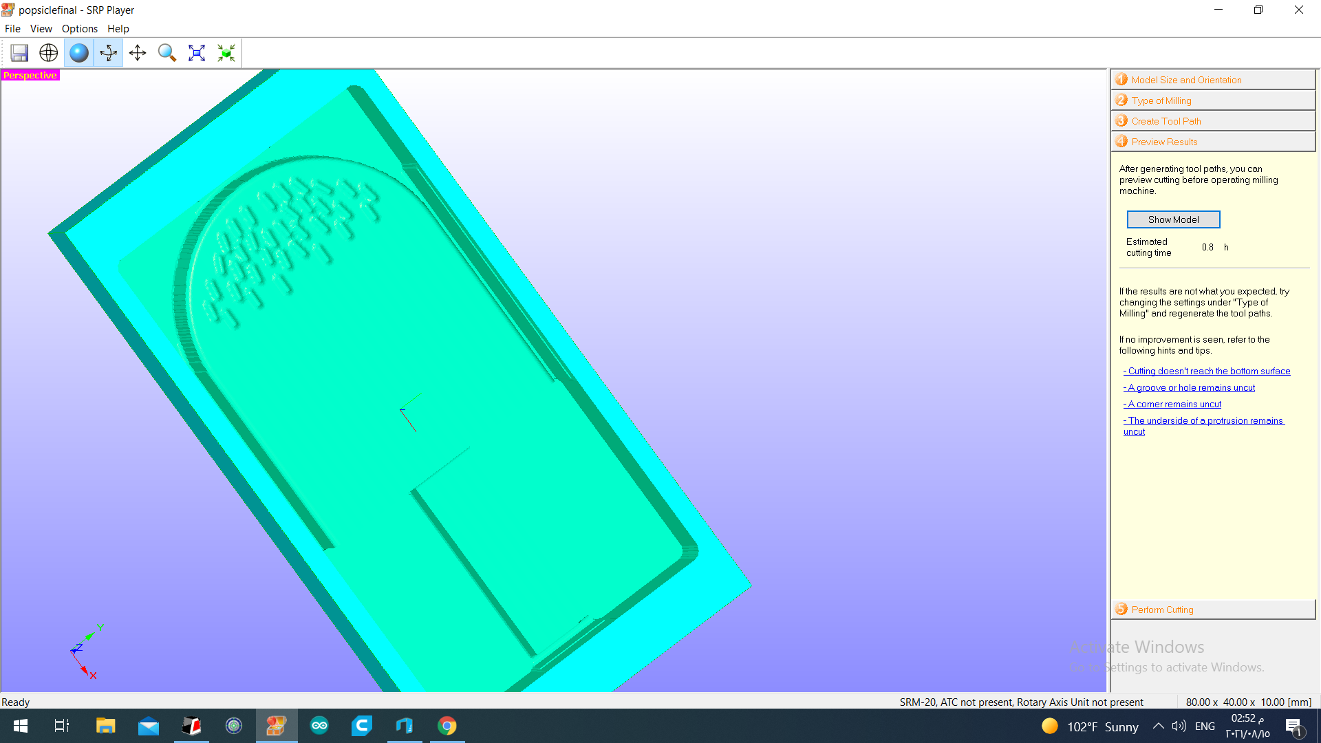
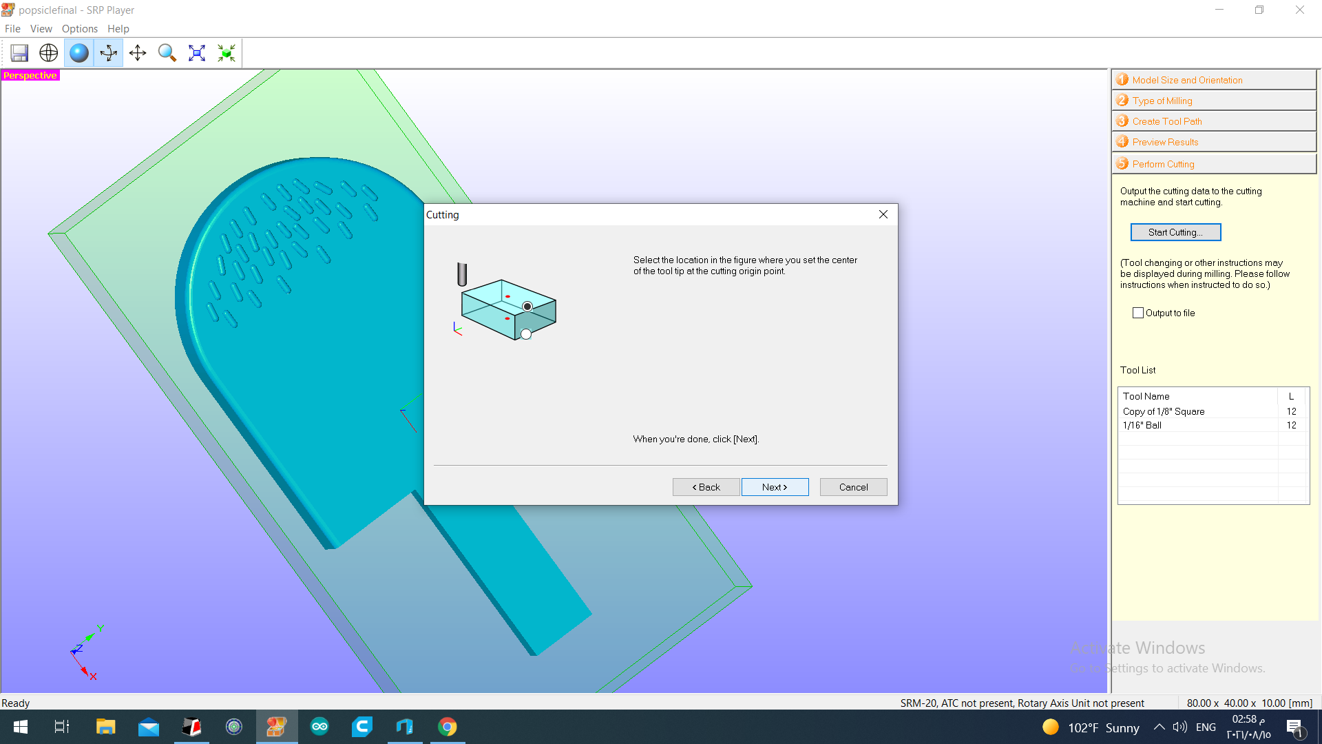
The fourth step is to preview results.
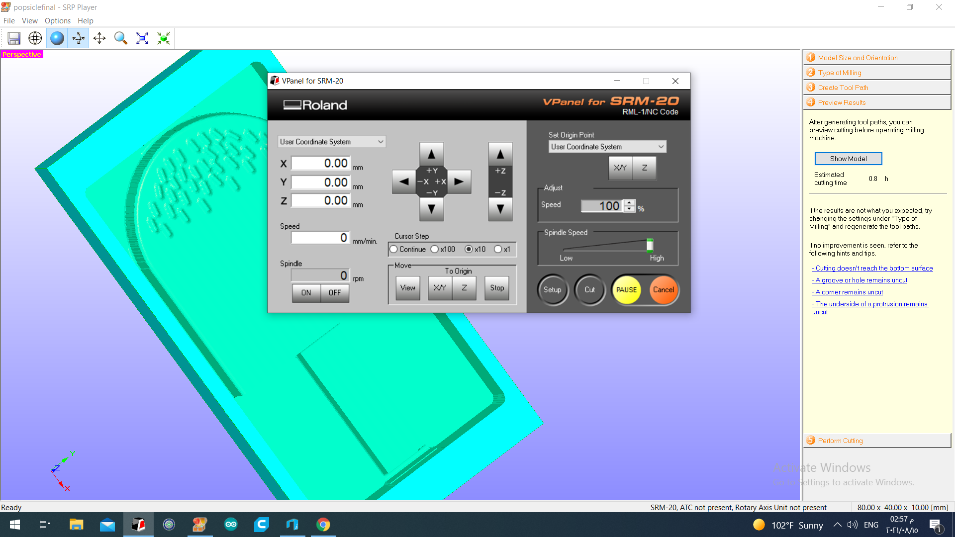
Prior to that, I adjusted the position of the drill bit, using VPanel. I adjusted the x and y and made sure the drill bit is at the center point of the workpiece. When doing this, it is okay to move the drill bit around at high speed. However, when adjusting the z position, I moved it at x10 speed to avoid collision of the bit and the block. I lowered the drill bit in the z direction as low as possible, then I unlocked the drill bit and lowered it a bit more manually in a way that it touches the surface of the block, I checked that there is no space between them by trying to fit a piece of paper in between, it did not pass in between. After setting the xy and z position, I set the origin point by clicking on XY and Z on the right side.
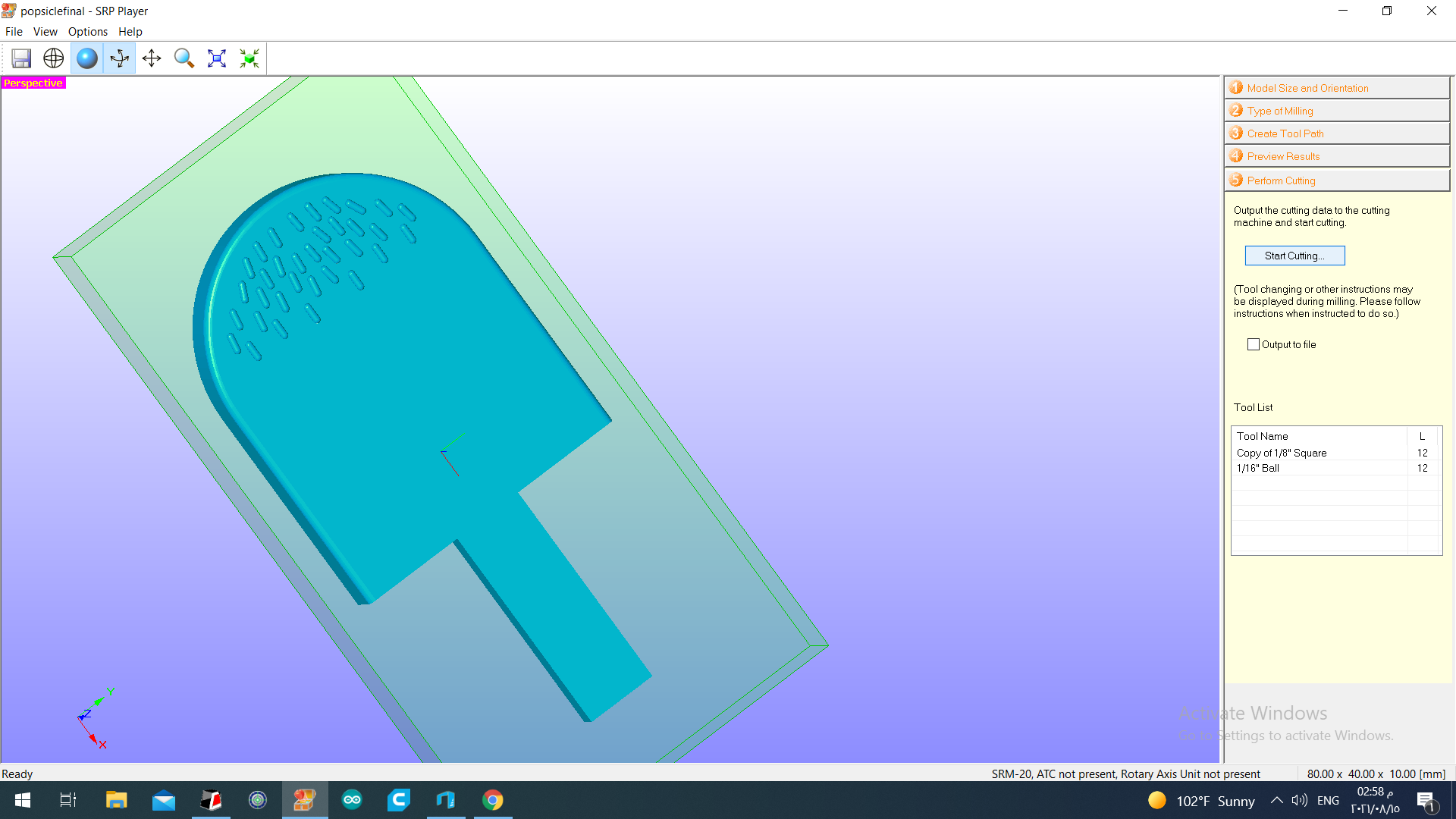
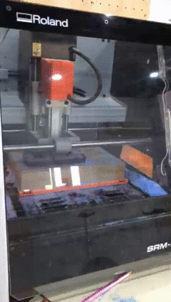
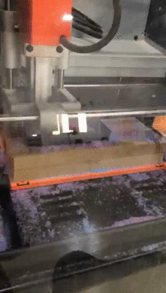
The fifth and final step is to perform cutting, I clicked on start cutting.


This gif illustrates the beginning of the roughing process.
After the roughing was complete,
I changed the drill bit, I put the 1/16 in. bit and continued the process.
The following gif shows the beginning of the finishing process.
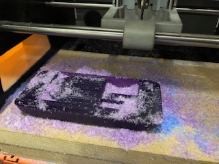
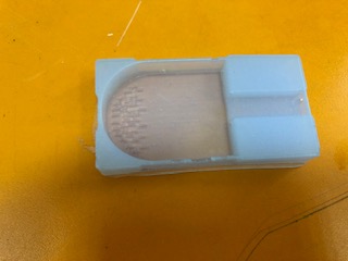
This is after the finishing was complete.
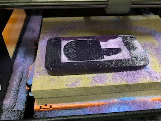
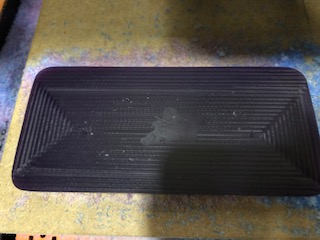
This is after I removed most of the wax shavings off the workpiece.
The next step is pouring silicone into the milled piece. I used a 2 part silicone system, it consists of two viscous fluids that must be mixed together within 15 minutes, one part is a rubber base and the other is a curing agent. Once mixed together, it solidifies. I mixed equal parts by weight of each fluid, it must be mixed at low speed to avoid bubbles.
After that, I poured the mixture slowly into the workpiece, and tapped it a bit to release the bubbles. This is the result, you can see that some bubbles are present, I guess I poured it quickly.
I let it sit for approximately 17 hours to solidify.
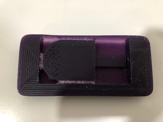
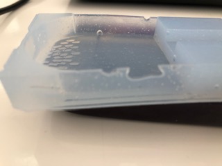
It solidified nicely. Then I gently removed it from the workpiece.
I think the silicone did not reach to the bottom and sides of the piece, that explains the dents in the silicone. As well as the bubbles, they burst and left empty spots.
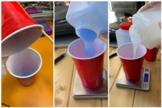
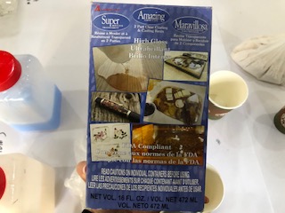
Next, I filled the silicone mold with epoxy resin. I used this product.
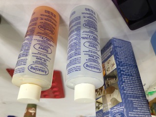
I mixed equal parts by volume of each fluid, and mixed them thoroughly to form a homogeneous mixture.
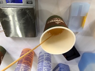
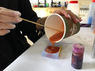
I added small amounts of red dye and glitter to the mixture.
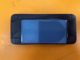
Then I poured the mixture into the silicone mold.
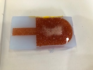
According to the instructions of the epoxy resin box, the mixture must be kept within the mold to dry for a minimum of 48 hours.
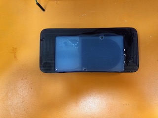
I left it to dry for 5 days, this is the result:
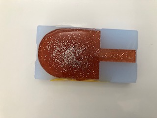
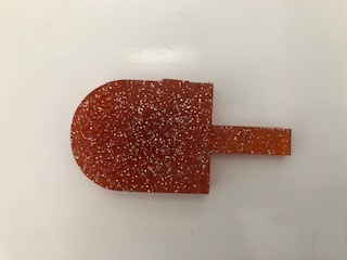
You can see in the picture below that there are some holes in the cast.
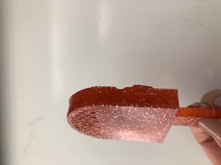
I believe the holes are because of the dents in the silicone mold and the air trapped within the epoxy mixture.

Safety of materials
I used three materials, wax, silicone, and epoxy resin. The safety data sheets for the materials are provided and discussed in the group assignment linked below.