7. Input/Output devices
Joystick Sensor
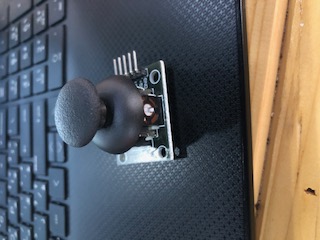
The joystick sensor is an input device that is commonly used on video games consoles, or other types of controllers that involve a joystick, such as trucks, wheelchairs, surveillance cameras, and many more. Joysticks are potentiometers, they return analog values.
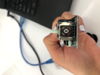
The joystick is covered with a plastic cap that you move around when using it. This cap covers the pins, the push button and the sensors.
The joystick has a removable plastic cap where you rest your finger when in use. When removing this cap you have a better view of the pins, the push button and sensors.
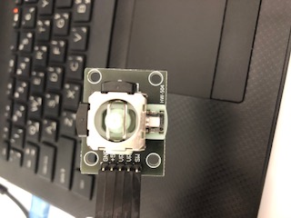
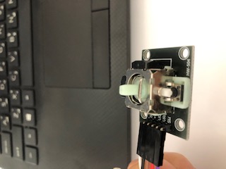
The two black covers on the side is the sensor housing.
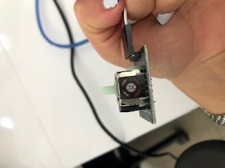
The sensor on the left side is the y-axis sensor, it is for up and down movement, when we move the stick up or down, the plastic cap hits the side sensor and it detects the up and down movement.
The sensor on the top side is the x-axis sensor, it is for left and right movement, when we move the stick left or right, the plastic cap hits the top sensor and it detects the left and right movement.
In addition to the y-axis and x-axis sensors that send an analog read, the joystick has a push button or a switch, when the joystick is pushed down, the switch is pushed down sending a digital signal.
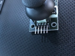
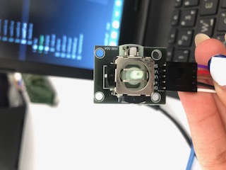
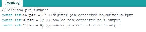
There are five pins on the joystick, namely, GND (ground) which is the negative power supply pin of the joystick, +5V (5 Volts) which is the positive power supply pin, VRx (x-axis) which is connected to the analog side of the Arduino, VRy (y-axis), SW (Switch) which is connected to the push button and it outputs a digital signal.
I connected the female side of the jumper cables to the sensor pins.
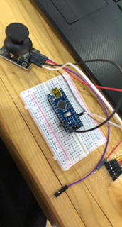
After that, I attached the Arduino Nano on the bread board, where every hole corresponds to the pin parallel to it. I connected the male side of the jumper cables to the bread board.
Sensor to Arduino Nano GND to GND +5V to 5V VRx to A0 (analog pin) VRy to A1 (analog pin) SW to D2 (digital pin)
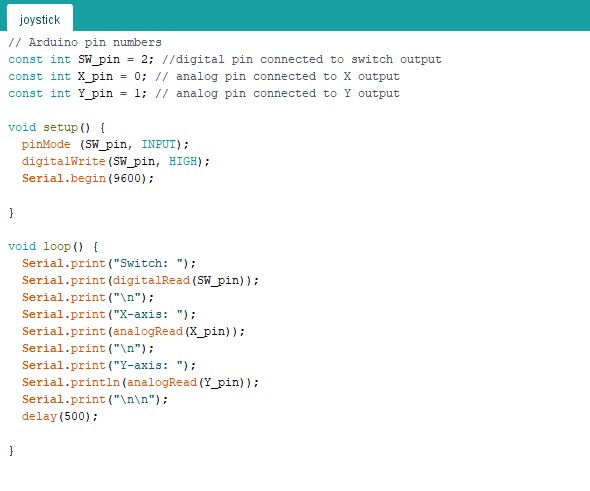
Then, I connected the Arduino Nano to the computer, and wrote the program
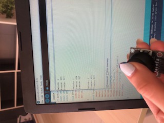
After clicking on upload, I clicked the on the serial monitor

This tab opened
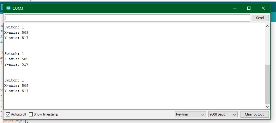
It reports the x-axis and y-axis position of the joystick, the positions shown in the above picture are the origin.
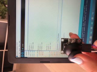
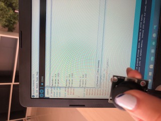
The x and y values change when moving the joystick around, as illustrated below

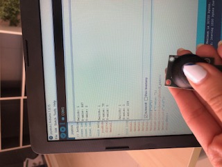
By switching the analog pins in the code for the x-axis and y-axis, we can make the sensor on the left detects the x-axis movement, and the sensor at the top detects the y-axis movement.
Flame sensor
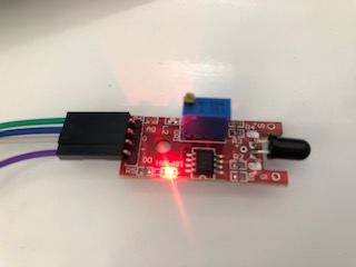
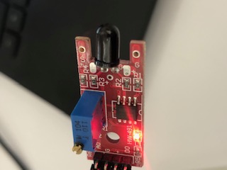
The flame sensor detects the infrared light emitted by fire. It is commonly used in fire detection systems. It provides both digital and analog output with sensitivity adjustment.
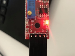
This module consists of an infra-red receiver LED, a dual differential comparator, a trimmer potentiometer, six resistors and two indicator LEDs.
There are four pins, A0 (analog output, connects to analog input on the breadboard), G (ground), ‘+’ (voltage common controller, 3.3 - 5V), D0 (digital output, connects to digital input on the breadboard).
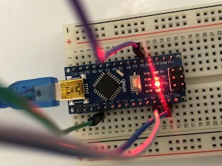
The same procedure of connecting the jumper cables to the joystick sensor is repeated for this sensor.
Sensor to Arduino Nano A0 to A0 G to GND ‘+’ to 5V D0 to D2

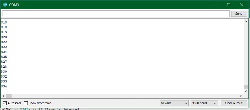
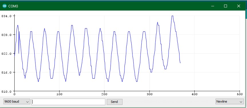
The values decrease when the flame gets closer to the sensor and increases when the flame moves away from the sensor.
Servo motors
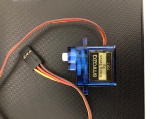

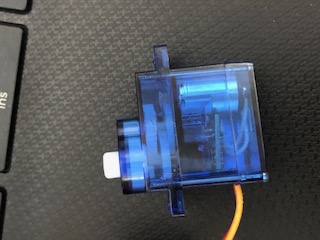
Servo motors produce high power output. They have integrated gears and a shaft that the position of can be controlled. They can move to a position accurately, and can rotate up to 180 degree. They are used in embedded electronic applications.
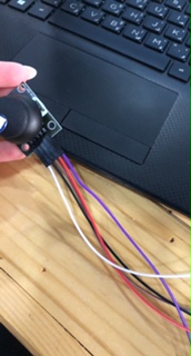
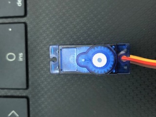
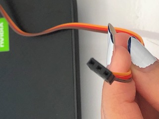
As depicted in the pictures above, there are three wires in the servo, power (red), ground (brown), and signal (orange).
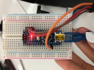
The wires are then connected to the Arduino Nano, on the bread board.
Servo to Arduino Nano Power to 5V Ground to ground (GND) Signal to digital (D9)
After connecting the wires, I ran the following code on Arduino
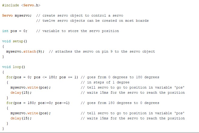
This is the result after running the code, the plastic blades rotated
Buzzer
Buzzers are used for making beeps, alarms and tones. They can be found in alarm devices, computers, timers and confirmation of user input such as a mouse click or keystroke. Buzzers are light weight, simple construction, and low cost.
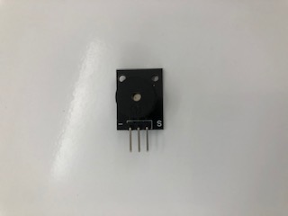
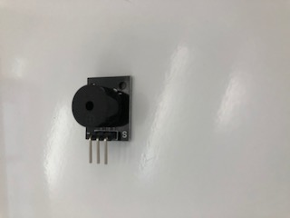
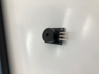
The buzzer shown above is called pin out buzzer. There are three pins, signal (denoted by S), input (in the middle), and ground (denoted by -).
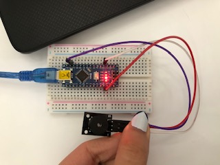
I connected the female side of the jumper cables to the pins and then to the Arduino nano that is attached to the bread board.
Buzzer to Arduino Nano S to D11 Input to 5V GND to GND
There are two types of buzzers, passive and active. An active buzzer generates the sound itself. While for the passive buzzer, you will have to send the sound signal to control the sound.
Active buzzer
The active buzzer generates sound when it is electrified, at only one frequency.
“The specifications of the active buzzer are as follows: Voltage range: of 3.3 – 5V Frequency: 2 KHz Size: 3.3 x 1.3 x 1.2 cm”
This the code for the active buzzer
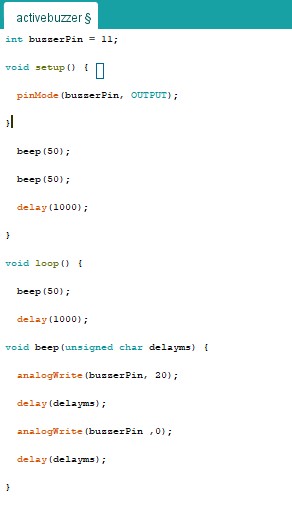
Changing the number within the beep() changes the sound of the buzz.
This is the link is to the clip of the result.
Passive buzzer
The passive buzzers need a sound signal to generate a tone.
“The specifications of the passive buzzer are as follows. Voltage range: 1.5 – 15V DC Tone generating range: 1.5 – 2.5 KHz Size: 18.5mm X 15mm [0.728in X 0.591in]”
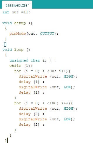
This the code for the passive buzzer
This is the link to the clip of the result.
Joystick with buzzer
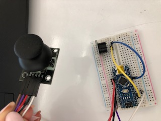
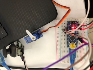
I connected the joystick (input) with the buzzer (output) on the breadboad, in the following setup:
Joystick to Arduino Nano GND to GND +5V to 5V VRx to A0 VRy to A1 SW to D2
Buzzer to Arduino Nano (I fixed the buzzer to the bread board) (-) to GND S to D8
Then, I entered this code on Arduino and clicked on upload
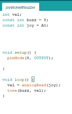
Below is the link for the result of this setup Joystick with buzzer clip
As the joystick is moved up and down (on the x-axis), the buzzer produces a sound, this setup only works for the x-axis.
Joystick with servo motor
I connected the joystick to the servo motor, in the following setup:
Joystick to Arduino Nano GND to A3 +5V to A2 VRx to A0 VRy to A1 SW to D2
Servo to Arduino Nano GND to GND (+) to 5V y-axis to D3
Then I ran the following code on Arduino
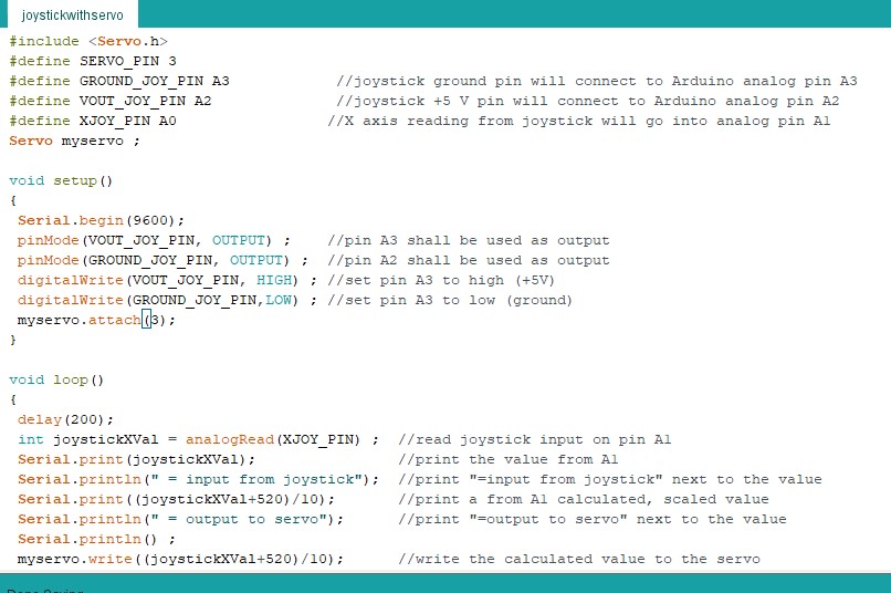
The fan blades of the servo motor rotate as the joystick is moved around. The result is shown in the link below