Designing a microreactor
3duf
The website used to create the microreactor is 3duf.org
I watched this short introduction first
Then I watched this tutorial to be familiarized with the website and its functions
After that, I saw some designs that were replicated from literature, to get a rough idea about the types of designs made and for what purpose
My instructor, Dr Salman, sent me this
The primitive table (scroll down to view it) is very useful, it gives a real representation of how each tool looks like when milled
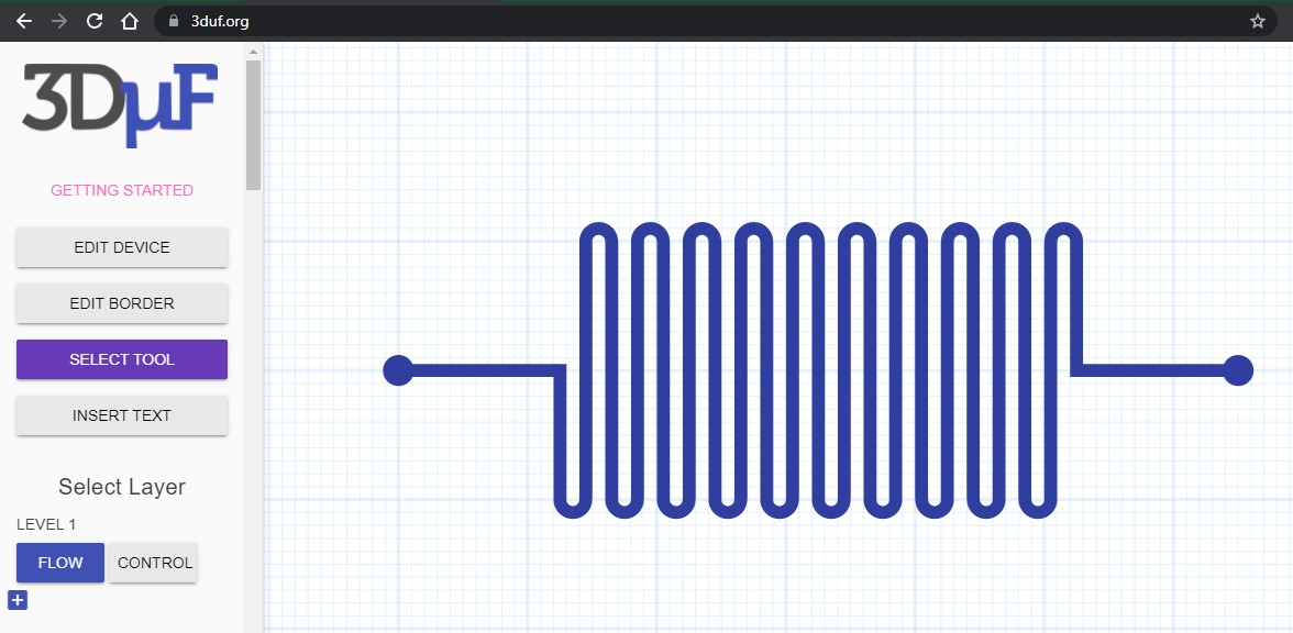
This is what 3duf.org looks like upon opening
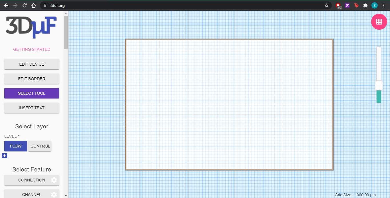
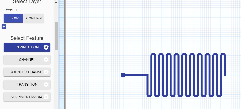
I worked on the flow layer mainly. I used three tools:
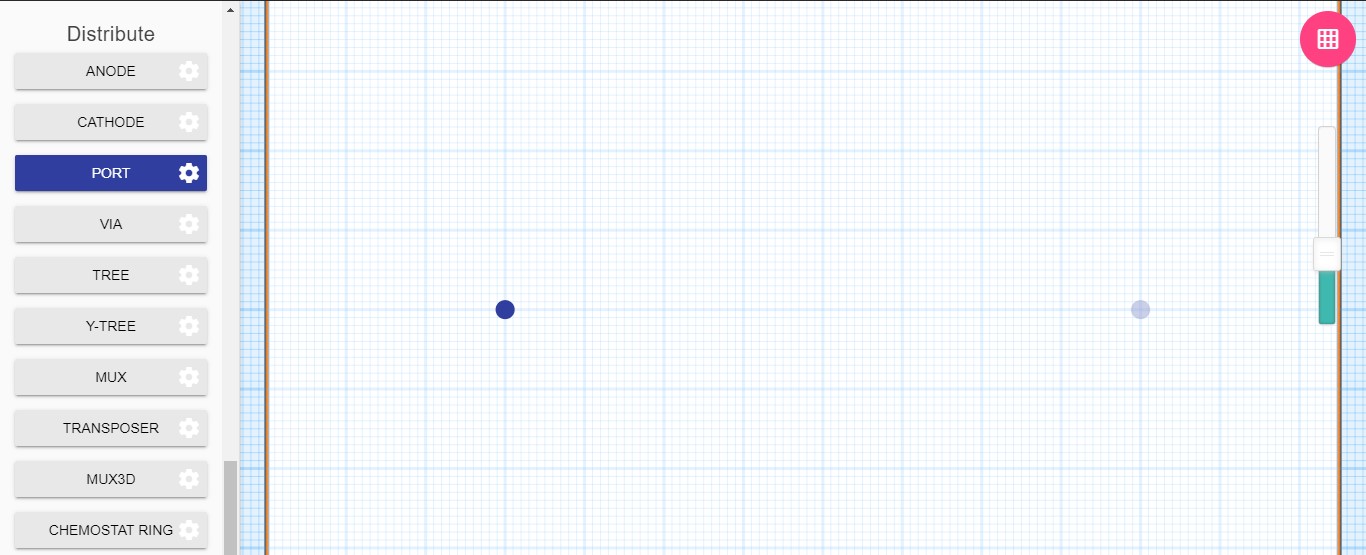
1- Port: to create the inlet and outlet of the reactor
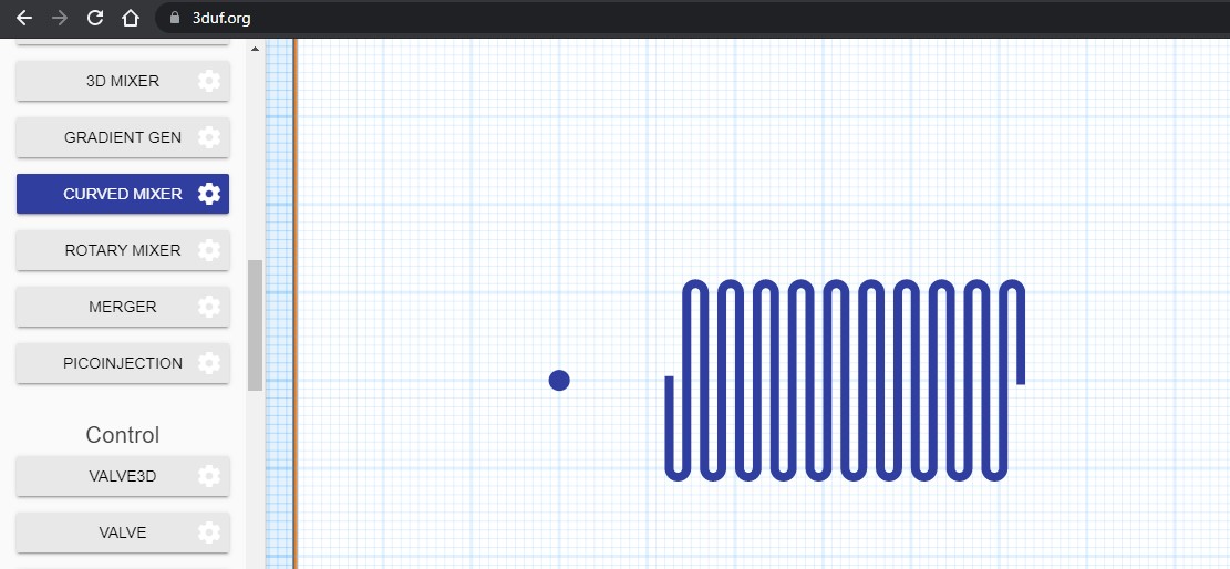
2- Curved mixer: to create the curved microchannel (rather than the mixer tool which generates a rectangular cross section)
3- Connection: to connect the inlet and outlet to the microchannel
Now, I will discuss the parameters I use when making the designs
Port
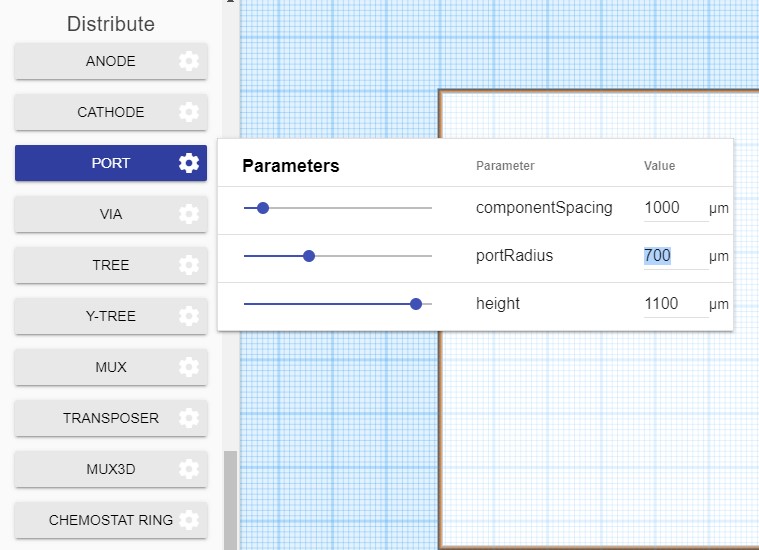
I only adjust the radius. I usually make it 0.2 mm bigger than the desired width of the microchannel. To further clarify, if I am planning to make the width of the microchannel to be 1 mm, I make the port radius 1.2 mm.
Curved mixer
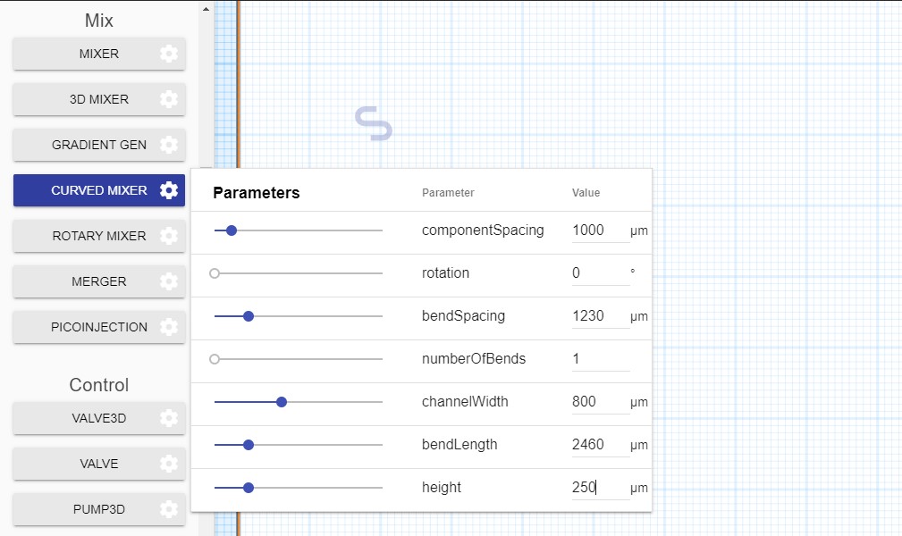
I change the rotation to 270 degrees, to make it horizontal. I change the channel width to my desired width. Consequently, I make the bend spacing equal to the width of the desired microchannel (channelWidth). I make the number of bends 10. And I make the bend length 20000, to make each bend long.
Connection
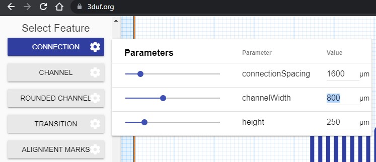
I make the connection width equal to the width of the microchannel.
Simple design
Using the parameters described above, I simple draw the ports and microchannel, align them, then connect them.
After completing the design, it can be exported in two formats only, JSON or SVG.
Personal review
3duf is simple and easy to use. However, you need to bare in mind that you cannot import and edit a design that you previously made. Once you close the window, that is it, you cannot edit more. In addition, sometimes the website gets stuck when you constantly modify the design. Also, it can only be exported in two formats, both are not compatible with CO2 laser machine and fine milling machine, so another program must be used to change the format of the file.
Design files
You can find some design files of different channel width in the link below.
Inkscape
Inkscape is a 2D design program. It is used after exporting the design file from 3duf, to transform the format to one that is compatible with the desired fabrication machine. In this step, all the layers are added, and the dimensions are checked. My colleague Mahmood is responsible for this part, more details can be found on his webpage.
Fusion360
Fusion360 is a 3D program. It is used after exporting the file from inkscape in dxf format, to transform it into an STL file. We do this step when we want to fabricate using the fine milling machine, because the program connected to it only accepts STL format. In this step, we can manipulate the depth of the microchannel, which is something we cannot do in 3duf. More details can be found on Mahmood’s page as well.
ImageJ
ImageJ is used to measure the depth of the microchannel after the fabrication process is complete. The depth of the microchannel cannot be manipulated on 3duf or inkscape, it is a function of the fabrication technique. Therefore, after each milling or cutting process, we measure the depth to check if it meets the design specifications. An in depth explanation can be found here.