4. Computer controlled cutting (CO2 laser + Vinyl cutter)
Hello everyone, this week we had to work with two machines, namely CO2 laser and vinyl cutter.
CO2 laser
The machine cuts and engraves various types of materials by shooting laser beams into the material at a specified speed and power percentage. The speed and power for cutting and engraving are dependent on the material properties and they can be adjusted prior to the cutting process using a computer program.
“In a Co2 laser cutter, light is produced when electricity runs through a gas-filled tube with mirrors at both ends. One mirror is fully reflective while the other one lets some light come through. These mirrors guide the laser beam into the material that is to be cut. The gas is typically a mixture of carbon dioxide, nitrogen, hydrogen, and helium.”[1]
Our task was to make a press fit design, meaning duplicated pieces that can be fit together. We were given several material sheets, I worked with cardboard of 1.15 mm thickness.
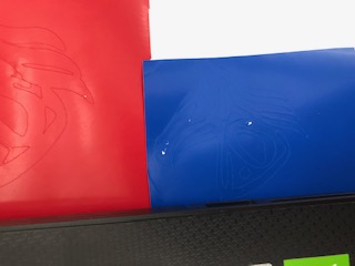
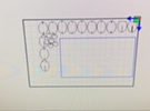
I looked for designs online, I wanted to make something similar to this
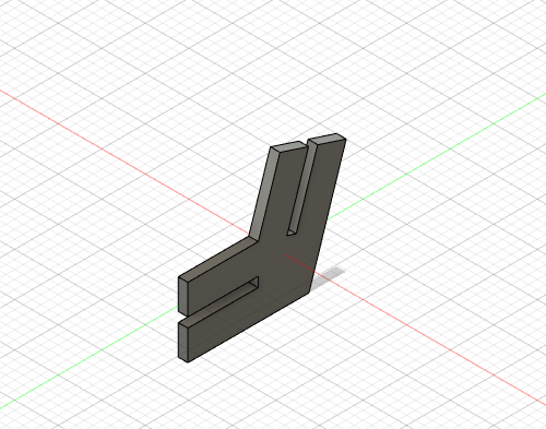
I made my design on Fusion 360, I started off by drawing an ellipse then rectangular carvings
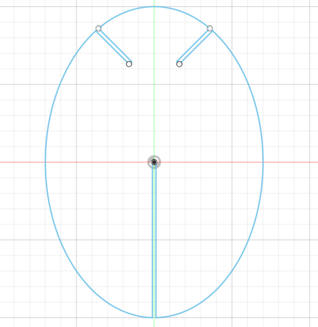
The thickness of the rectangles is 1.15mm, which is the thickness of the cardboard sheet. I made the thickness parametric, so that I can easily change all the thickness values after I perform the fitting test and find the best fitting.
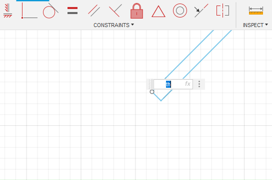
I went to modify>change parameters
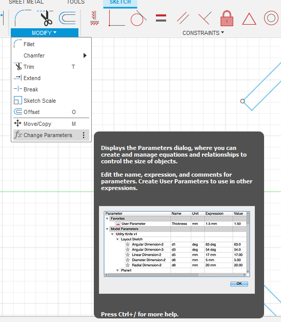
I clicked on add user parameter, I added the name and expression value which denotes the 1.15 mm thickness
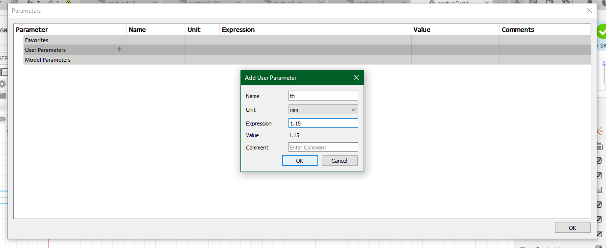
After that, I changed the dimensions of each thickness on the sketch to “th” instead of the numerical value, this way when I change the value of the thickness of the parameters table, all the values will change consequently, rather than just manually adjusting each value
I did this parameters table in every sketch I made for the reason stated above
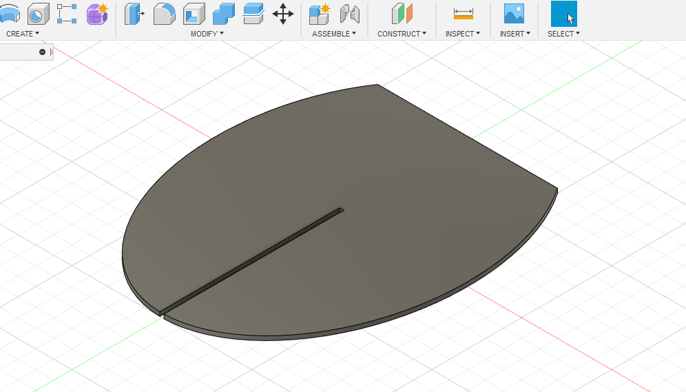
Then I extruded the sketch to 1.15 mm just to further illustrate how the part will look upon cutting
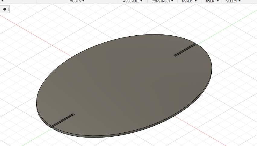
The first sketch had 3 connection spots, the long split will be attached to a base piece, which is the next sketch I made, whereas the two splits at the top are to attach other pieces to them and make it look like a cactus with many branches
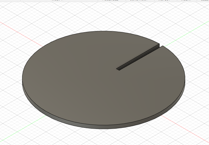
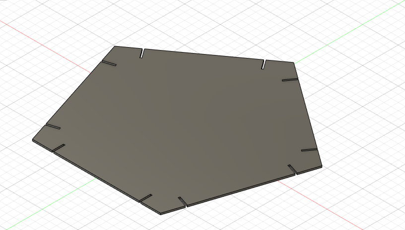
This is the design of the second piece I made which is the base piece, I did the same exact procedure as described previously but I made a horizontal line on one side of the ellipse and trimmed the part of the ellipse that lies outside of the drawn line, this way I will have a straight line on one side and the piece can act as the base of the cactus
After that I made a piece that will be cut multiple times
The last piece is circular instead of elliptical, it wil be at the end of each branch
I exported each sketch to dxf files which is the format that the computer program connected to the laser machine can understand
Next step after completing my design is adjusting the machine settings
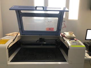
This is what the laser cutting machine looks like
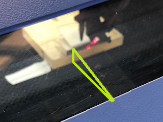
We learned how to measure the focal length with the aid of Pythagorean theorem
We let the laser machine run at low power so that it would not cut out the material used when measuring the focal length which was PMMA
I did not take a clear picture unfortunately, but we made a setup, the thickness of the boards stacked on the left are known and we measure the distance between the boards and the edge of the PMMA piece with a ruler so the unknown would be the hypotenuse which is the focal length of the laser beams
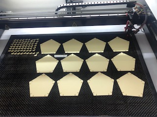
After that we adjusted the origin, then we did a test to find the optimum speed and power percentage for the machine to do the cutting neatly and precisely, below is the result of the test
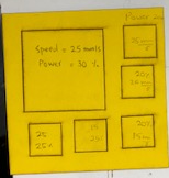
According to the results obtained, the optimum speed is 15 mm/s at a power of 25%
I imported my files on the program in the computer and organized them
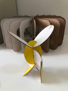
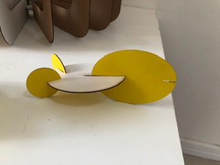
I cut the pieces and assembled them
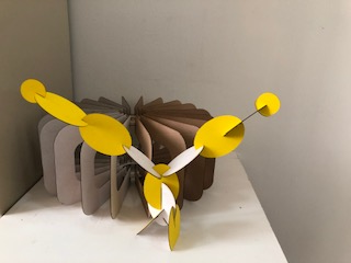
I did not like it, it was not very stable, but the pieces I made are versatile there are different ways to be assembled
So I decided to make another design, I attempted to recreate this
https://www.pinterest.com/pin/6685099437064986/
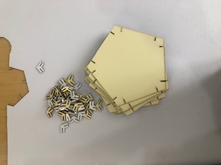
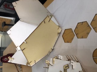
I made a sketch of a 5 sided polygon, I made splits all around with the aid of the mirror tool and I made the design parametric
The following pictures show the pieces after the cutting and during the assembly
More details are provided in the group assignment
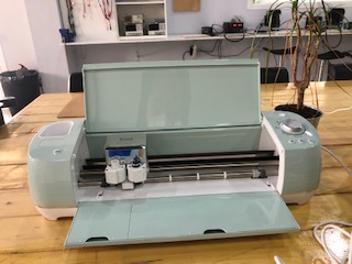
Vinyl cutter
Vinyl cutter is a machine that cuts vinyl material. It is connected to a computer containing a program called “Cricut design space”. This is what the vinyl cutter looks like
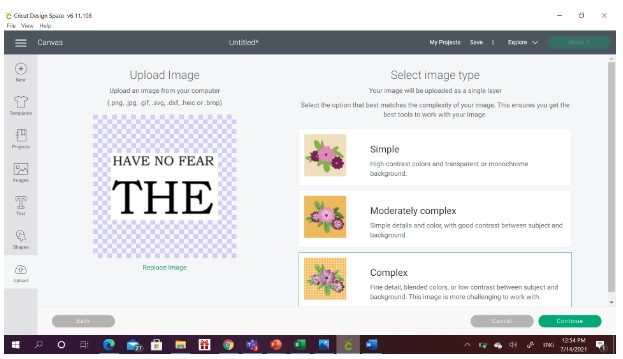
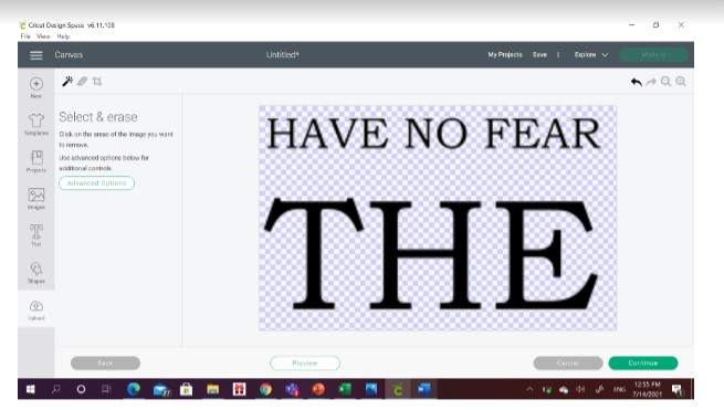
First, you have to choose or design an image with a clear background and edit the dimensions of the image. This is the image I chose to print and make stickers of

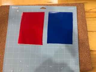
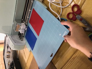
After that, I prepared the sticky board that goes inside the machine, I chose the vinyl colors I wanted to cut on and cut the sheet in the dimensions I wanted, then I stuck them on the sticky board
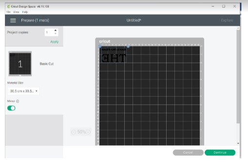
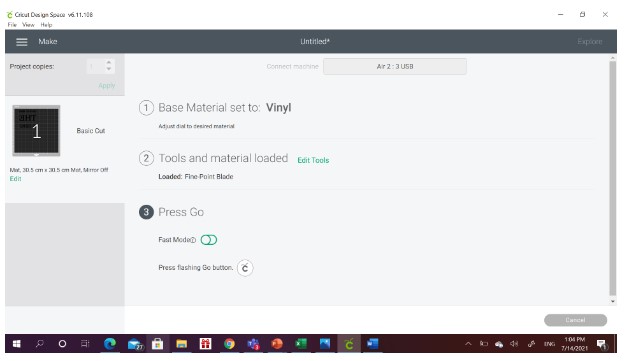
Then, I launched the program on the computer, I will show the steps my colleague Batool did, unfortunately I do not have screenshot of my own steps
This is what it looks like after cutting