Fabrication of a microreactor
Several fabrication techniques for PMMA (polymethyl methacrylate) were examined in literature, namely, computer numerical control (CNC) machining, CO2 laser technique, photolithography, etching, and inject molding. Only two of those techniques are available in Fab Lab, CNC machining (fine milling), and CO2 laser.
CO2 laser
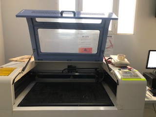
The machine cuts and engraves various types of materials by shooting laser beams into the material at a specified speed and power percentage. The speed and power for cutting and engraving are dependent on the material properties and they can be adjusted prior to the cutting process using a computer program connected to the machine. The program connected to the CO2 laser machine (RDWorks) only accepts dxf files.
The first step prior to the fabrication is testing the different settings for the laser machine. Several parameters can be manipulated, such as power (%) and speed (mm/s).
We tested two functions in the CO2 laser machine, cut and scan.
Cut
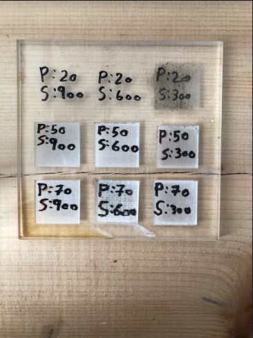
To test the effect of one variable, we have to maintain the other variable constant. So, once we kept the power percentage constant, and varied the speed. Then, we did the opposite, we kept the speed constant, and varied the power percentage. This process is illustrated below.
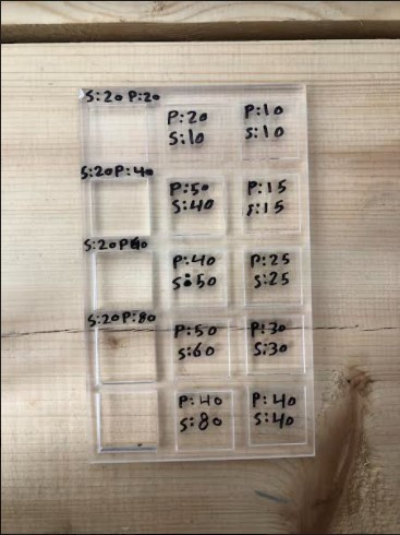
We found that a power of 80% with a speed of 20 mm/s achieves the best cut, when repeated 3 times.
We use this cut function to cut the boarders of the microchip.
Scan
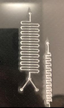
The scan mode is basically engraving. We use it to engrave the microchannel on the previously cut piece.
We tested the speed and power in the same manner described above for the cut.
Different setting result in different depths of the microchannel. We constantly check different values to achieve the depth we want.
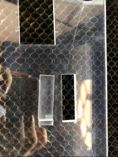
These are some samples we made.
Modifying the microreactor
Sealing
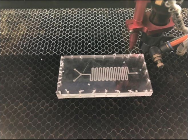
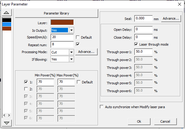
After numerous successes in fabricating the microchips with the CO2 laser, we performed laser welding. The concept of laser welding is to stack two pieces on top of each other and join them by the heat of the laser. We cut a piece of PMMA in the same size of a previously fabricated microchip, then we lay the microchip on the bed of the laser machine, and we lay the piece that we cut on top of it. We adjust the focal length of the laser beam. Then, on the program connected to the laser machine, we draw circles where we want the laser beam to hit, the heat from the laser melts the PMMA and makes both pieces stick to each other. The circles that we draw have to be a bit far from the engraved microchannel, so that the heat of the laser does not distort the microchannel or melts it and seals it as well, which results in blocking the microchannel and no fluid would pass through it.
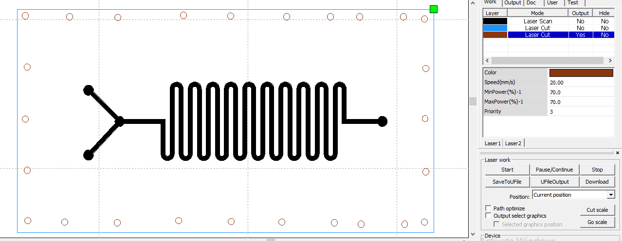
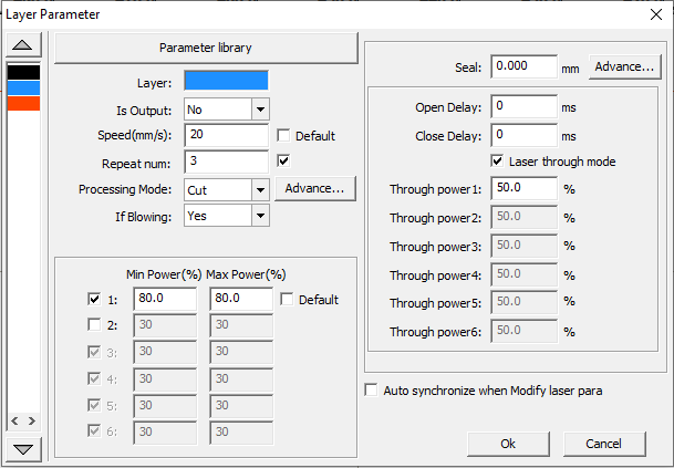
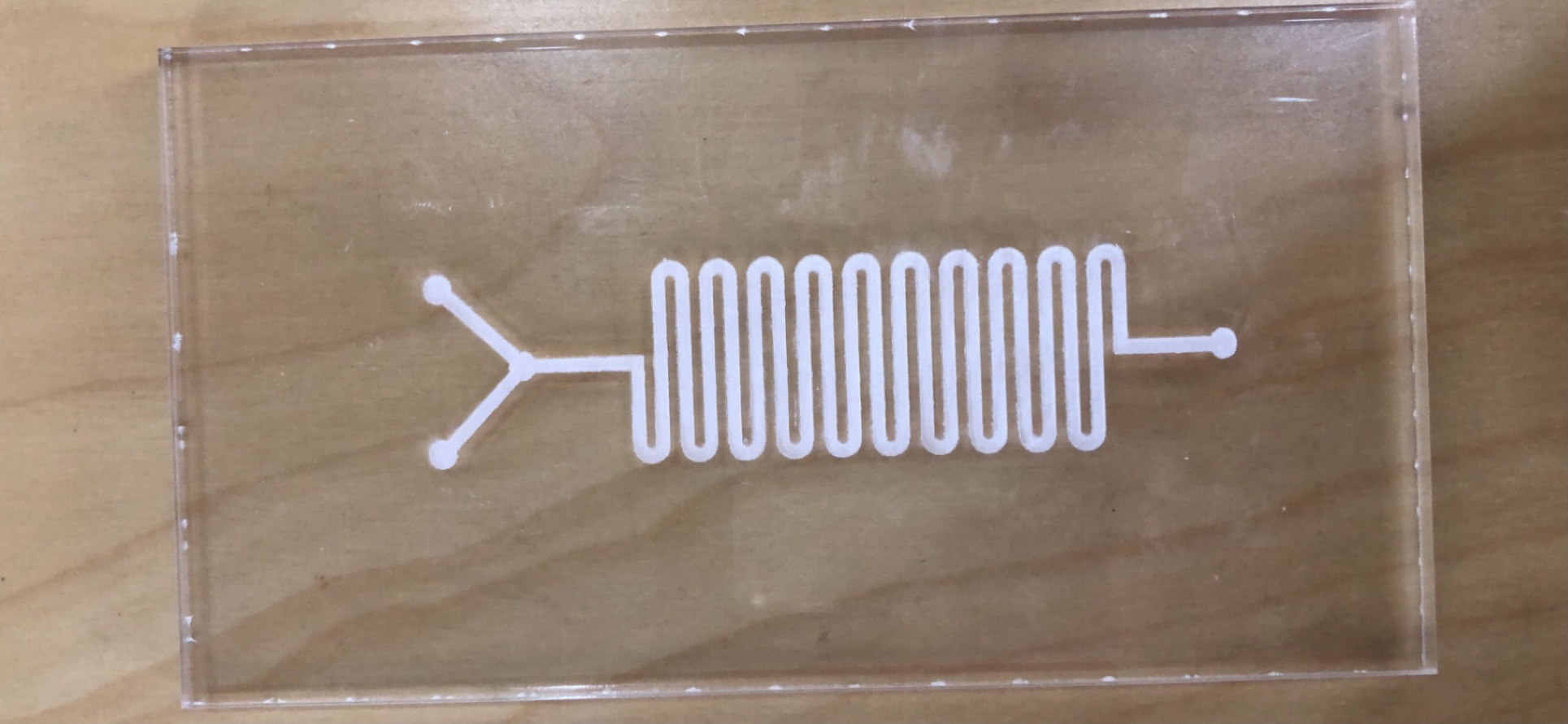
After experimenting, we found that a speed of 20 mm/s and 70% power, repeated 8 times, results in effective sealing.
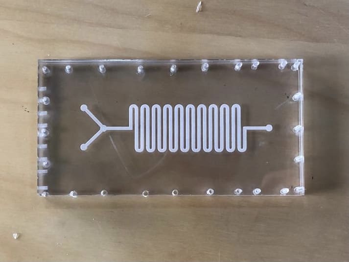
This is the result
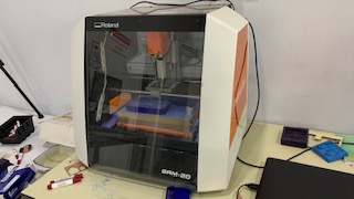
Fine milling machine
This is a picture of the milling machine, it is called Roland SRM-20, and it is connected to a program called SRP player which was designed exclusively for the machine. SRP player only accepts STL files, so the designs have to be converted to STL to be able to perform this fabrication method.
The use of different sized drill bits result in different quality and cleanliness of the microchannel engraving. We tested one drill bit, 1.35 mm, and our aim was to test out smaller ones, to achieve higher precision.
More details about the machine and how to adjust the drill bit can be found in my documentation for Fab Academy.
I will show a step by step on how to adjust the parameters of SRP player to achieve the desired result for microchannel engraving.
First, you need to have a workpiece. We cut the PMMA sheet with the CO2 laser rather than on the milling machine, to reduce the duration of the process. We cut it using the optimum parameters described above for CO2 laser machine. The dimensions (width, length, height) of the workpiece must be known, and the center of it must be indicated.
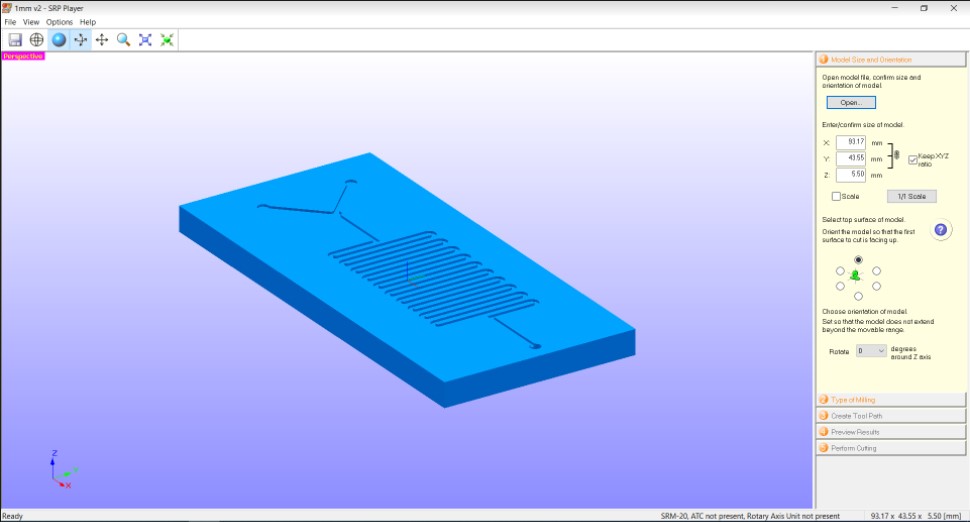
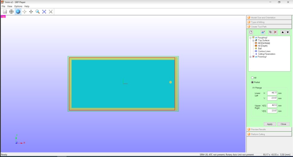
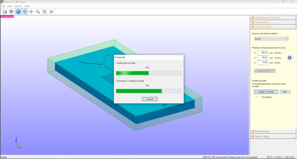
In the first step on the SRP player, you have to specify the dimensions of the model, meaning the dimensions of the microchip that you designed on 3duf and edited on Fusion360, you have to specify the length, width, and depth.
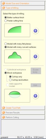
Second step is to select the type of milling, we wanted to achieve good quality so we clicked on better surface finish, the designs we made were all of round cross section, so we chose model with many curved surfaces, we only wanted to do engraving, so we selected cut top only.
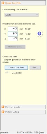
In the third step, the material of the workpiece must be specified, we worked on PMMA, so we chose acrylic, along with its dimensions (the dimensions of the piece of the PMMA sheet that we cut with the laser).
Then, within the third step, we click on edit, we change the cut area to partial, and we manually move the red lines and put them over the blue rectangle.
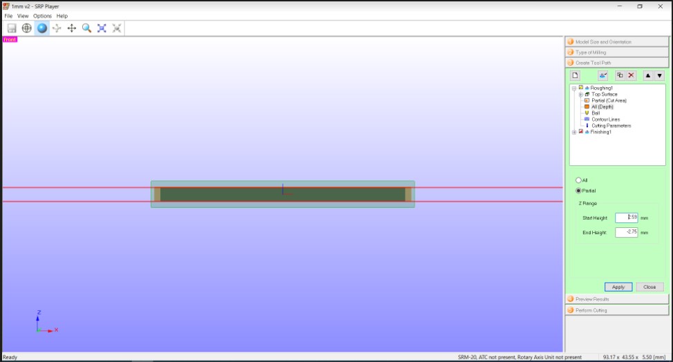
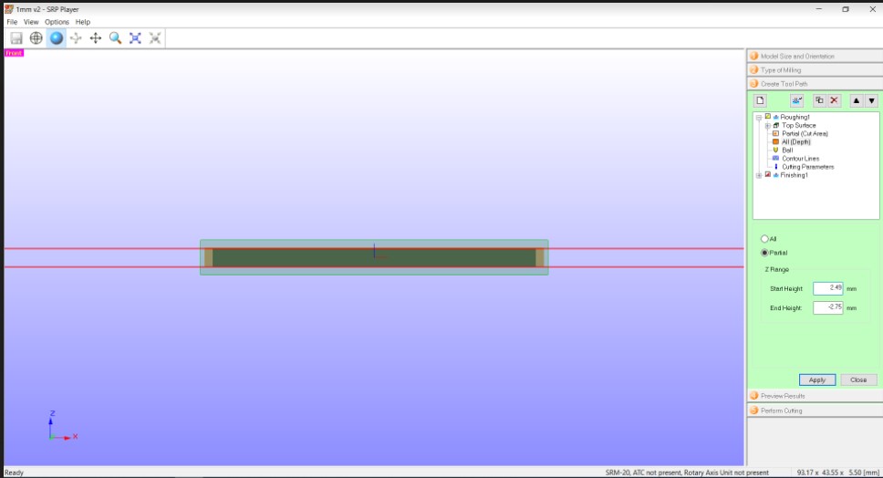
After that, we make the depth partial as well, and move the red lines to the boarders, then we reduce the start height by 0.1 mm
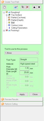
Next, we select the “ball” (drill bit) size
We repeat the same steps for the finishing process.
After that, we click on create tool path
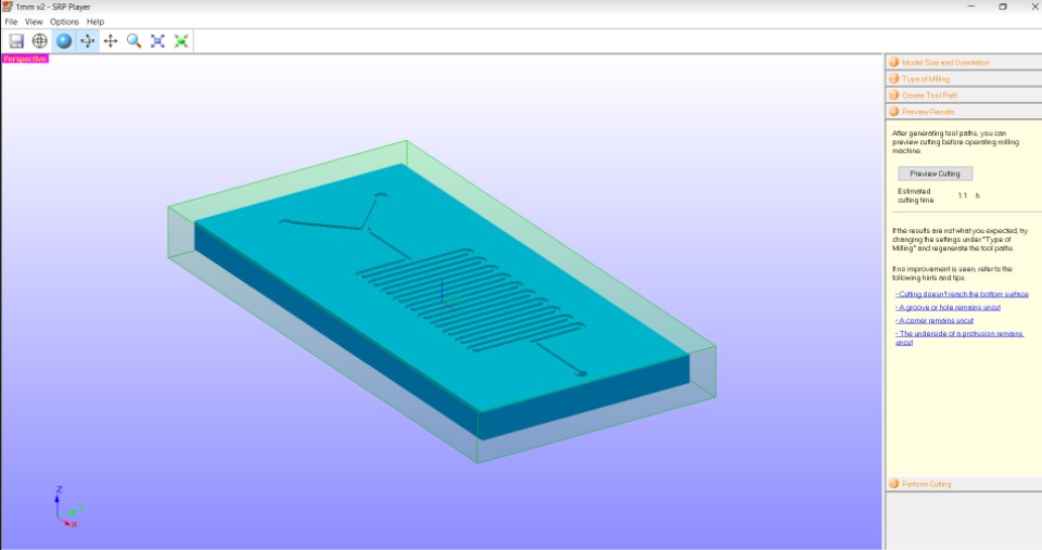
In step 4, we can see the estimated time for the whole process, and we can see a preview of the expected result.
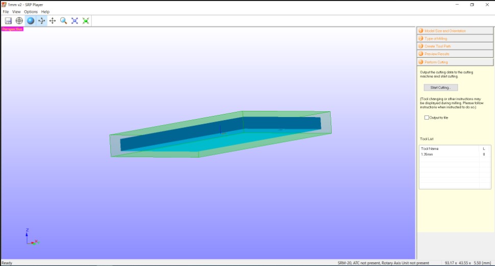
Lastly, in the fifth step we click on start cutting, to start the milling process.
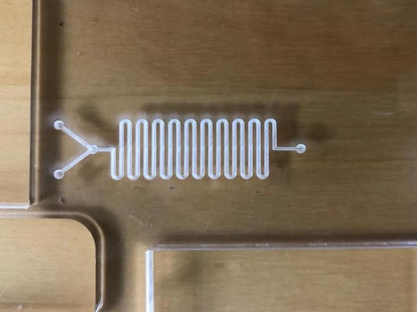
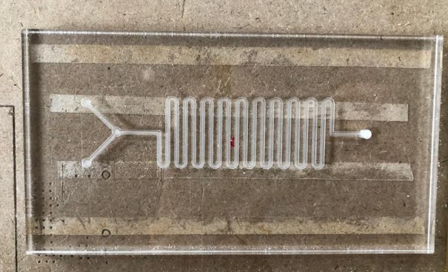
The following picture shows a microchip that was fabricated with the milling machine with a 1.35 mm drill bit, following the same steps described above.
Comparing results
The main advantage of CO2 laser over the fine milling machine is that it is fast, it does not take a long time to perform the engraving, the process duration is considerably less than the milling, it takes minutes to complete the fabrication, whereas the milling takes hours. RDWorks which is the program connected to the laser machine is easy to use, and not many steps are required to fabricate the microchip. You just have to adjust the focal point and origin in the machine, and select the speed and power and number of repeats in the program to perform the fabrication. On the other hand, there are many steps and adjustments that have to be made in order to do the milling. That is because SRP player was not designed to fabricate microchips, by default it performs molding and casting, we have to manipulate the program and machine to achieve our desired results. Although CO2 laser has some advantages, the milling achieves better results and higher precision. The microchannels engraved with the milling are clean. In addition, the depth of the microchannel is specified exactly and achieved when doing the milling, whereas in CO2 laser different powers and speeds result in different depths. Another disadvantage of the milling machine is that when working with microfluidics, small drill bits must be used, those small bits break easily, and have to be handled with more care. All in all, each technique has its pros and cons, the choice of technique depends on the desired results, if high precision is required and time is not an issue, fine milling is suitable, if precision is not important and you aim to just test sealing or incorporating a catalyst in the reactor, CO2 laser is the right option.