3. Large format CNC
This week was all about applying the skills we learned from 3d designs software to create a design that will be cut and assembled via a CNC machine.
Group Assignment
Designing a Foot Stand
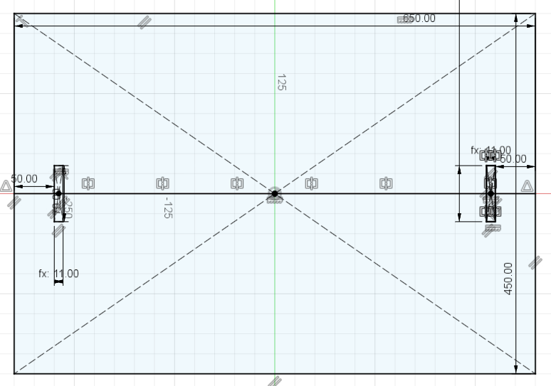
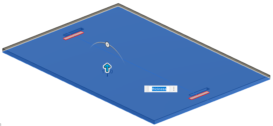
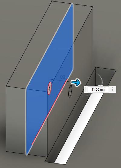
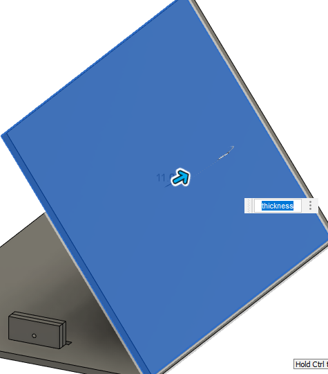
The first step is sketching the base of the design and extruding it. In this design the extruding thickness should be noted as 11mm since the MDF sheet provided thickness is 11mm too.
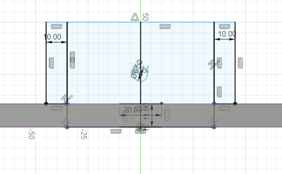
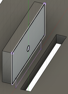
The next step is to sketch the what I will call the level controller and extruding it.
Since the level controller needs to be on both sides, we use mirror feature to do that.
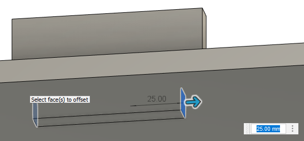
We use the offset tool then to fill the gaps.
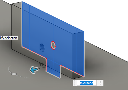
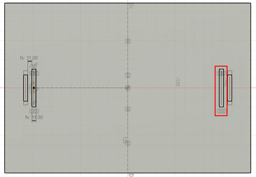
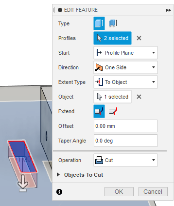
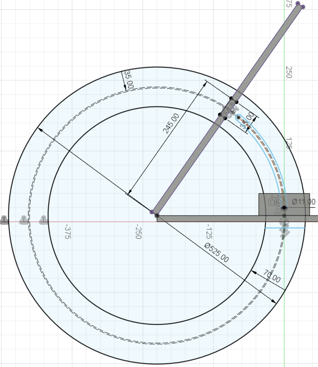
Then we edit the skitch to add a hole for the slider later on. Then applying the extrude to cut the hole.
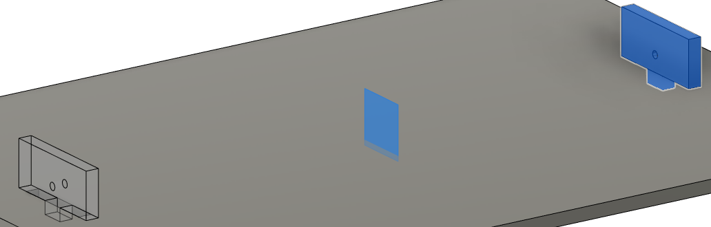
For the level controller we don’t want it to be close to the slider hole therefor we extrude another copy of it just to reference a gap size because otherwise if we left it close to the gap it might breaks in the future.
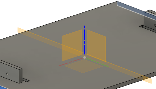
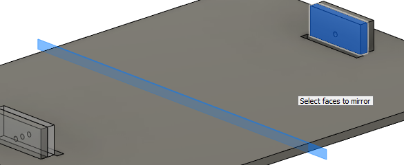
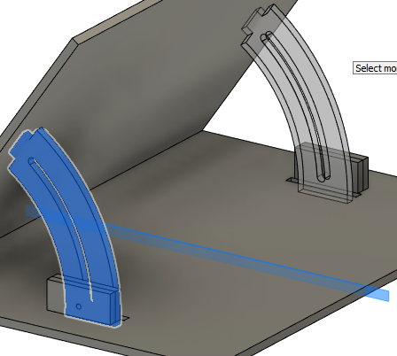
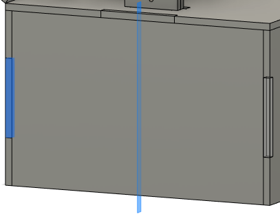
To mirror the level controller to the other side we add a middle plane and use the mirror tool to mirror it.
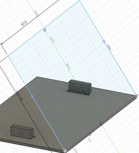
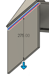
After that we start sketching the foldable part by creating an angle plane and sketching on it, then extruding the sketch.
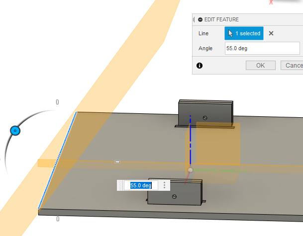
Then we start sketching the part that will be used to adjust the level of the foot stand and extrude it in both sides.
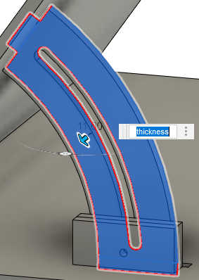
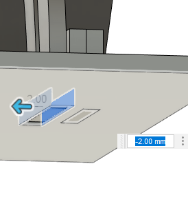
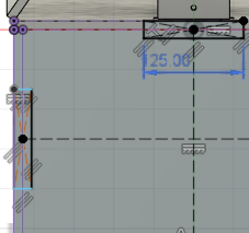
We add an offset to the gap where the level adjuster will enter so that we give it more free space.
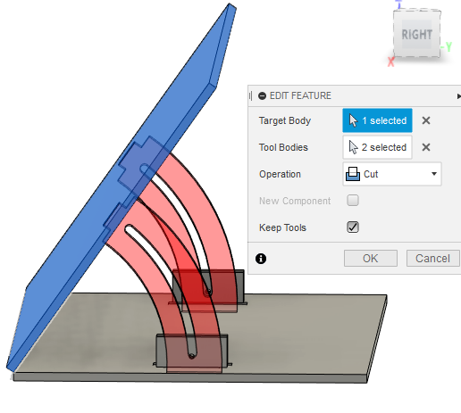
By using the combine tool we can separate parts form another bodies just like we did here.
Then we take the base sketch to create four sides to be the stand for the whole body.
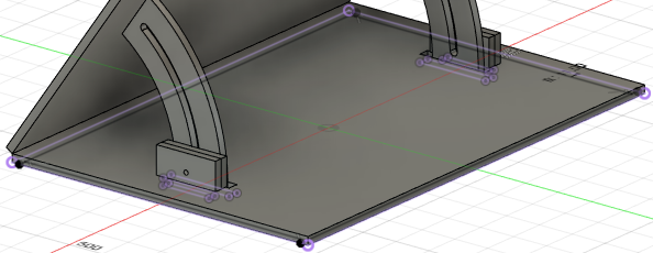
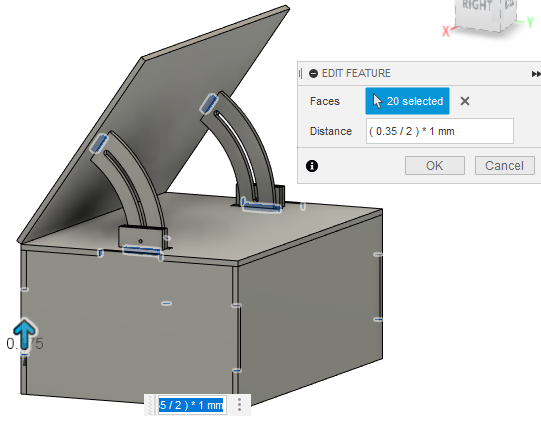
After completing the base design we start adding joints the first step is to sketch them, followed by extruding and mirroring on all sides.

In order for the joints to joint actually we need to offset the by few millimeters so that it stuck when we start the assembling part.
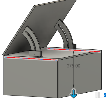
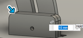
we add fillets at the sides.
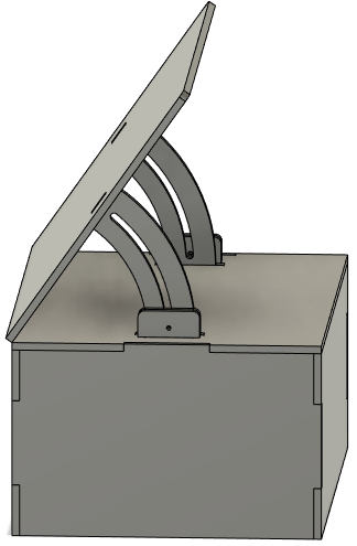
The final look of the design.
Finally, for the machine to be able to read it we need to save all the sketches in a dxf format files.

Downloadable files
CNC Machine Setup
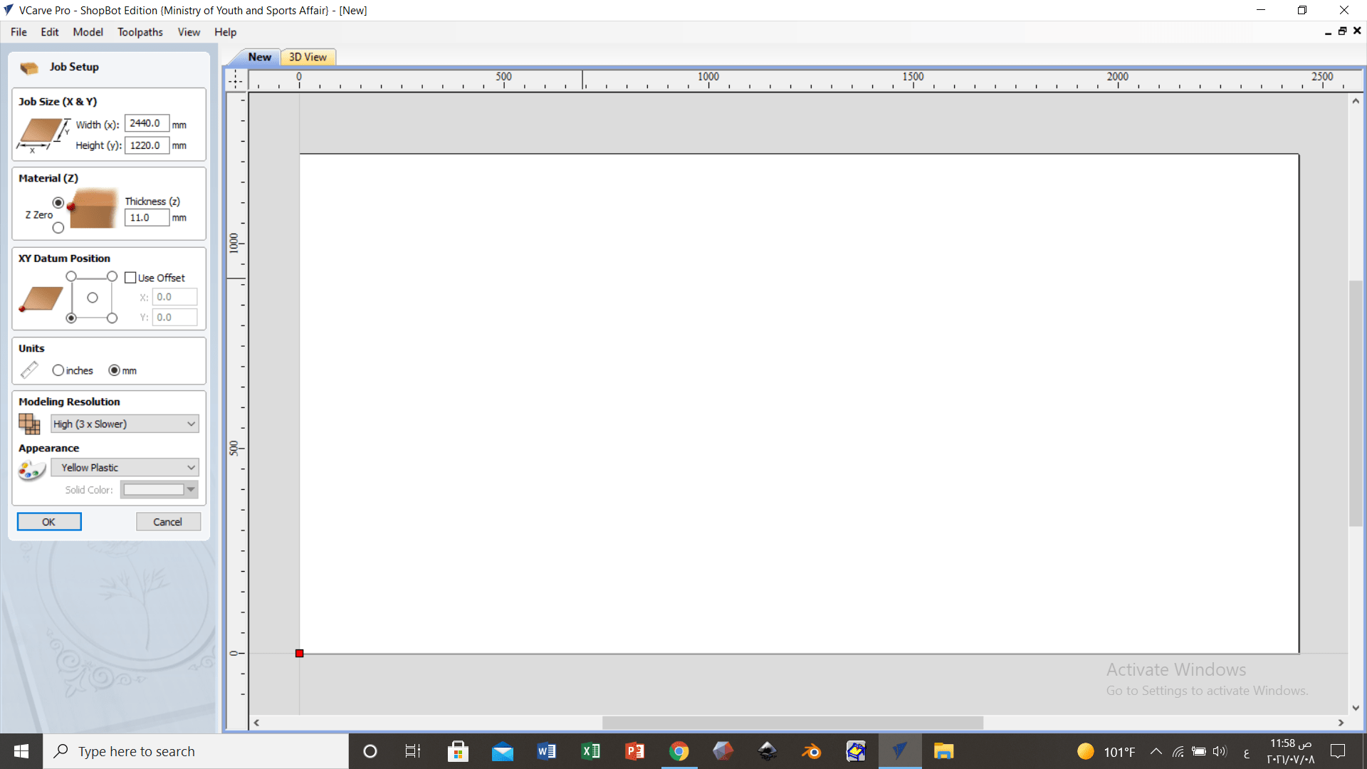
The machine found in the lab is connected to a software called VCarve, this software enables you to change the speed, feed, toolpath and even do 2D drawing. At first we need to specify the sheet width, height, and thickness.
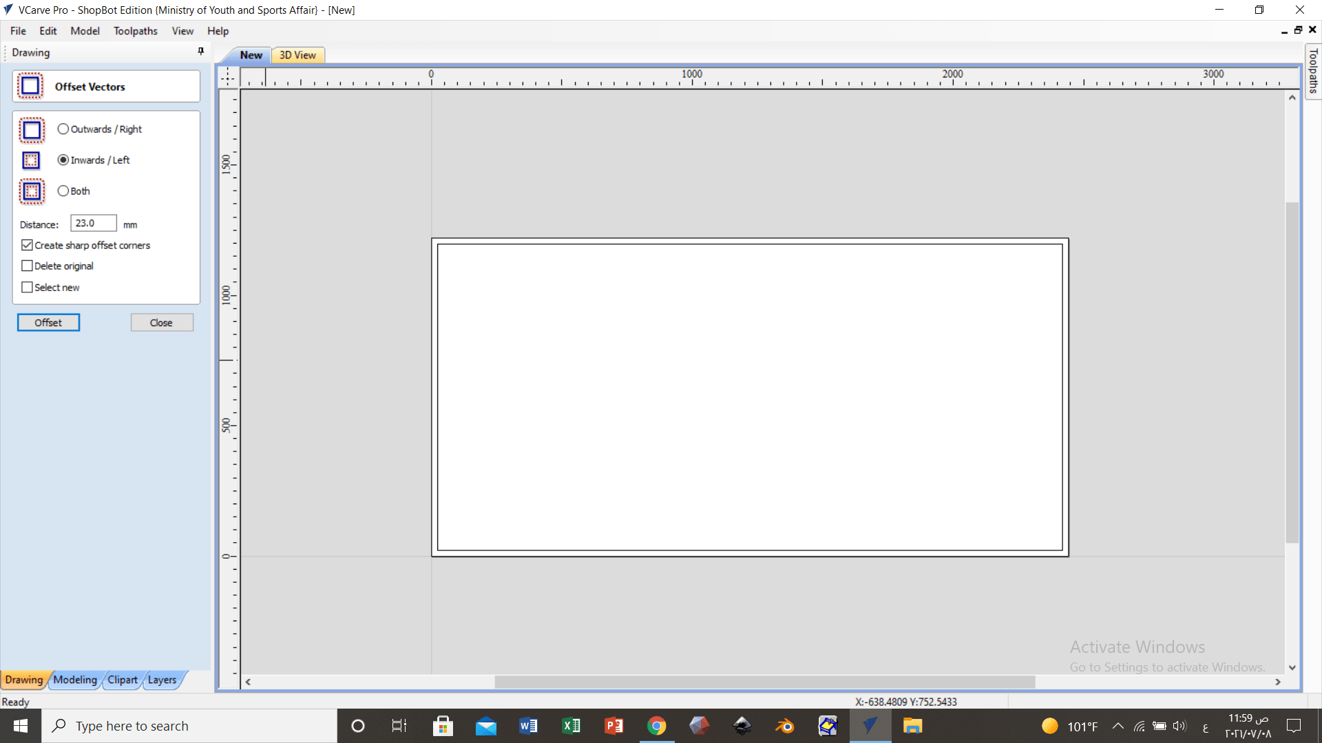
Creating Offset to act as a safe wall so that the drillpit always stays in the sheet.
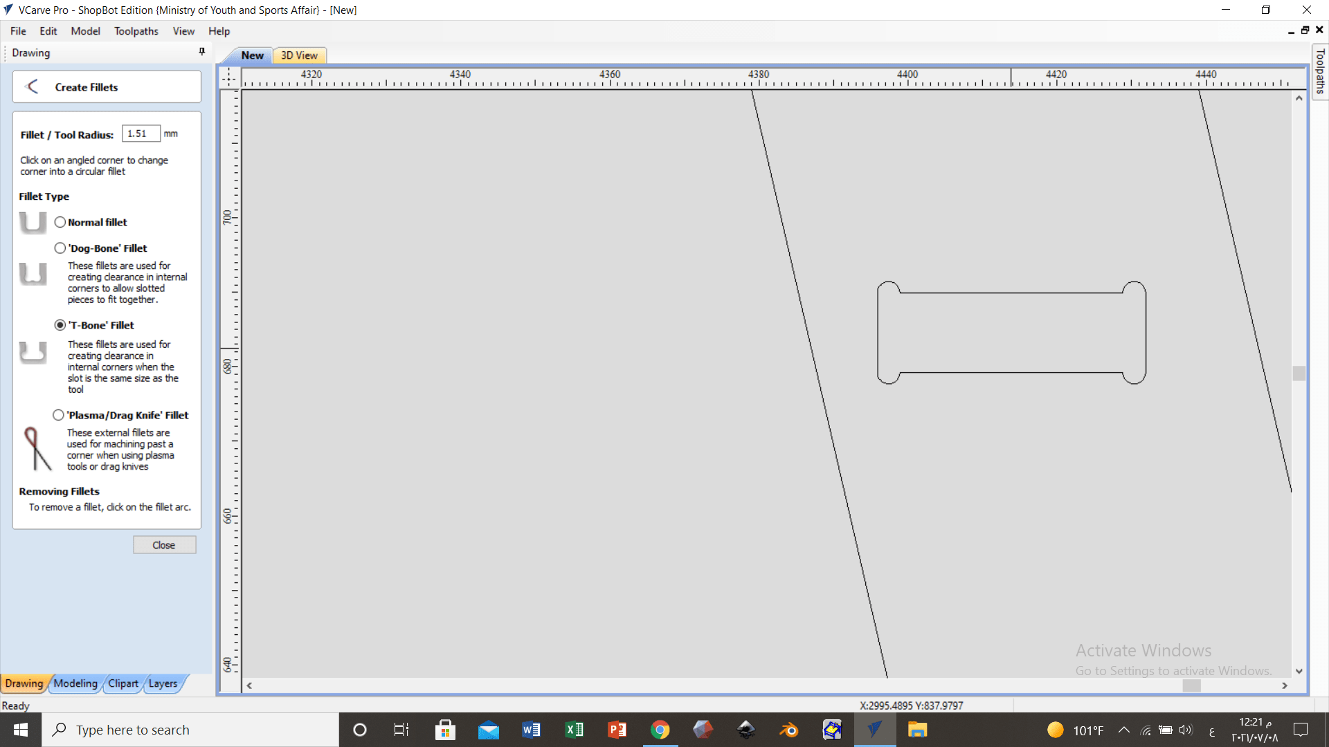
Adding Dog bone to the inside edges is necessary to ensure that the device will cut the corners perfectly.
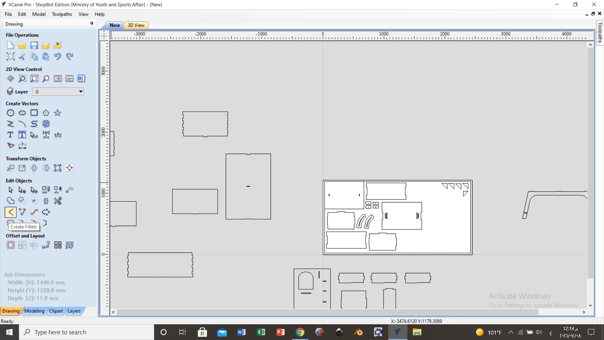
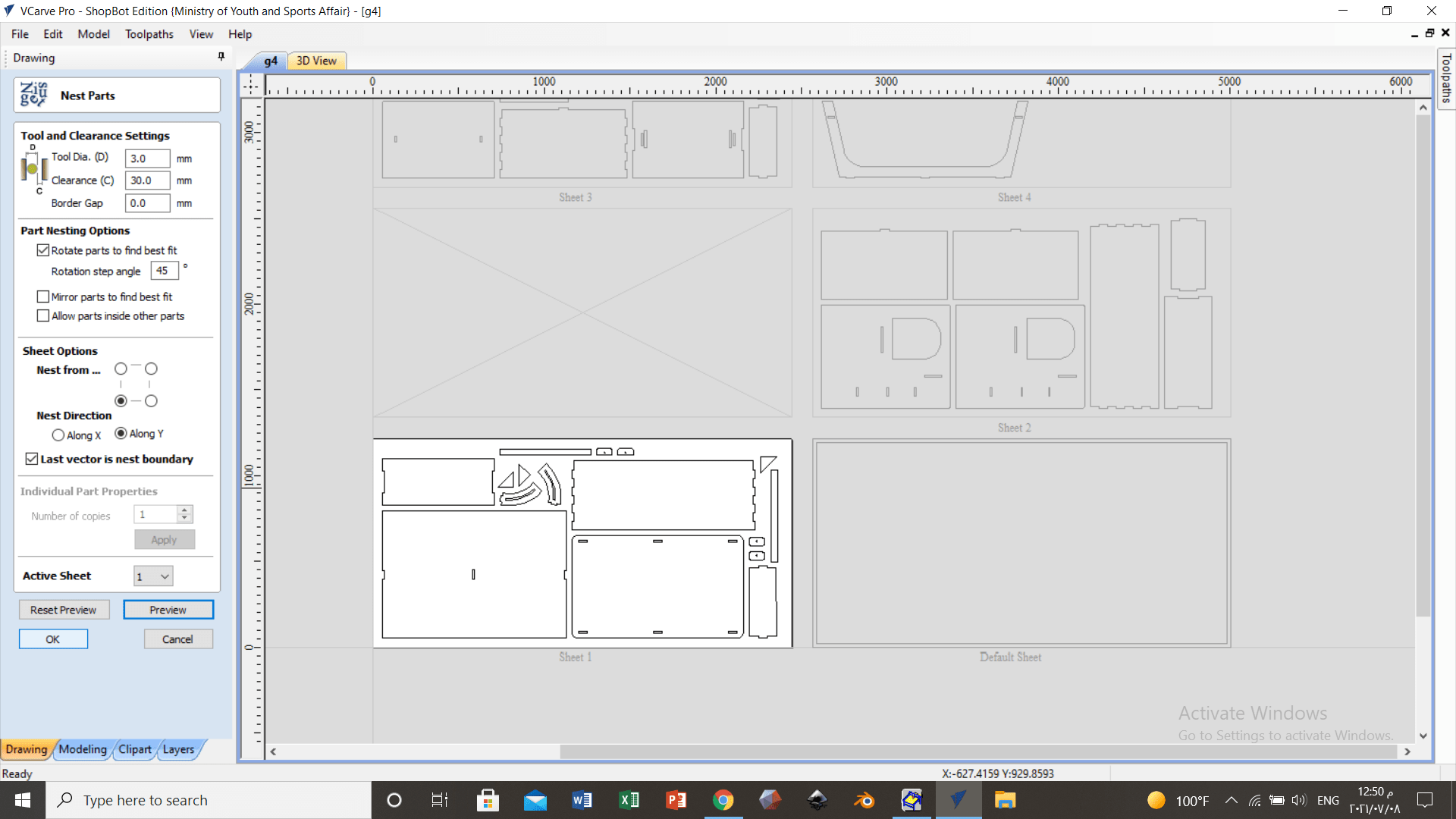
Rather then organizing every part manually there is a feature called nesting which does it automatically.
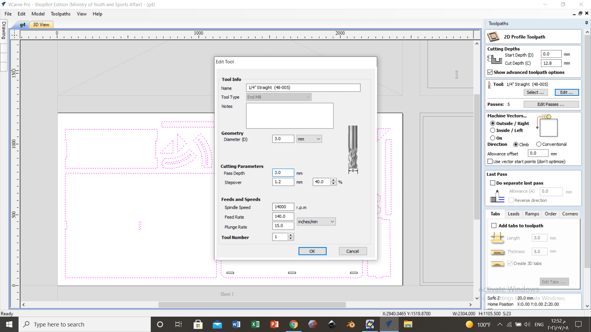
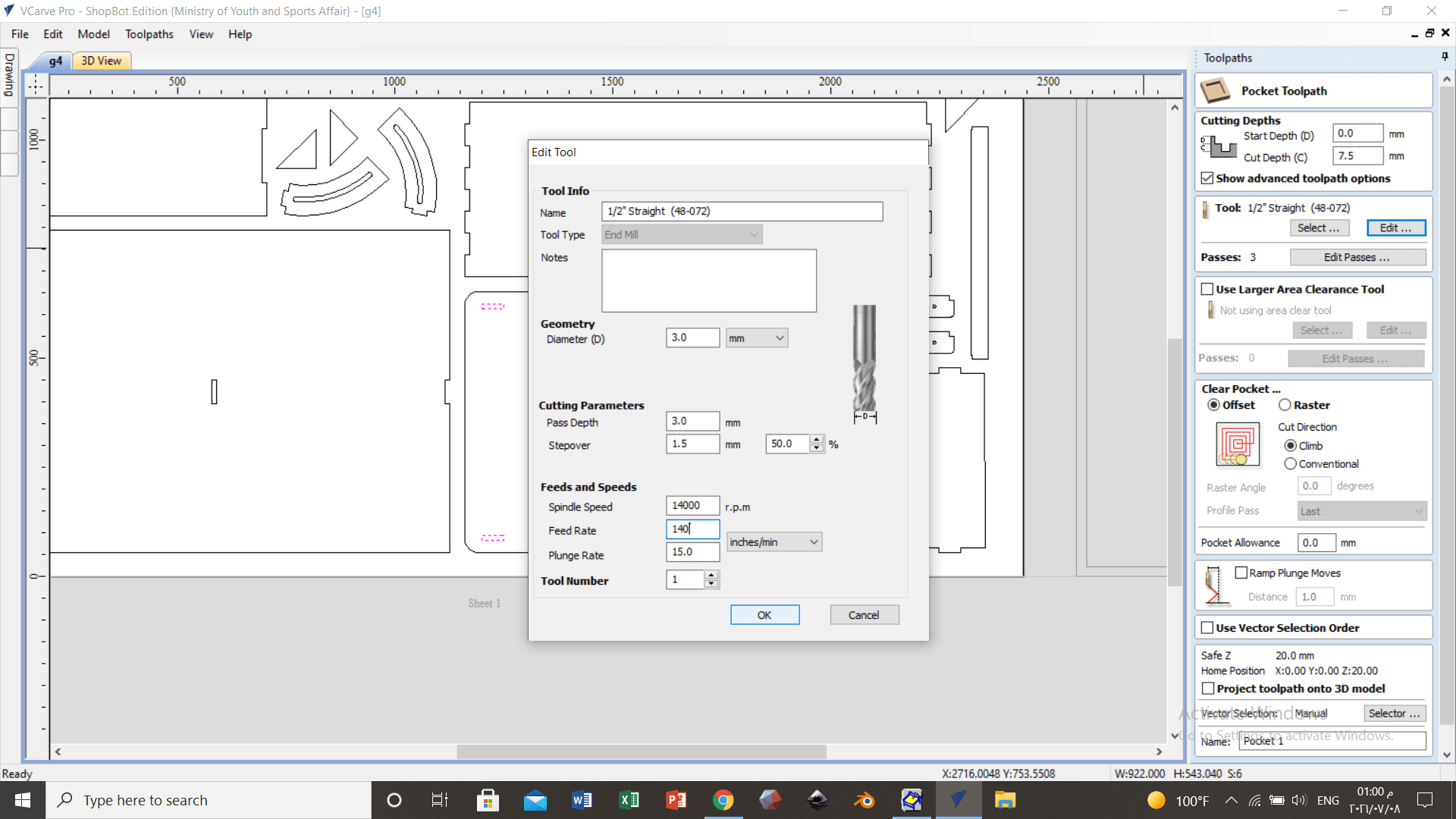
Using toolpath feature to edit the drillpit parameters.
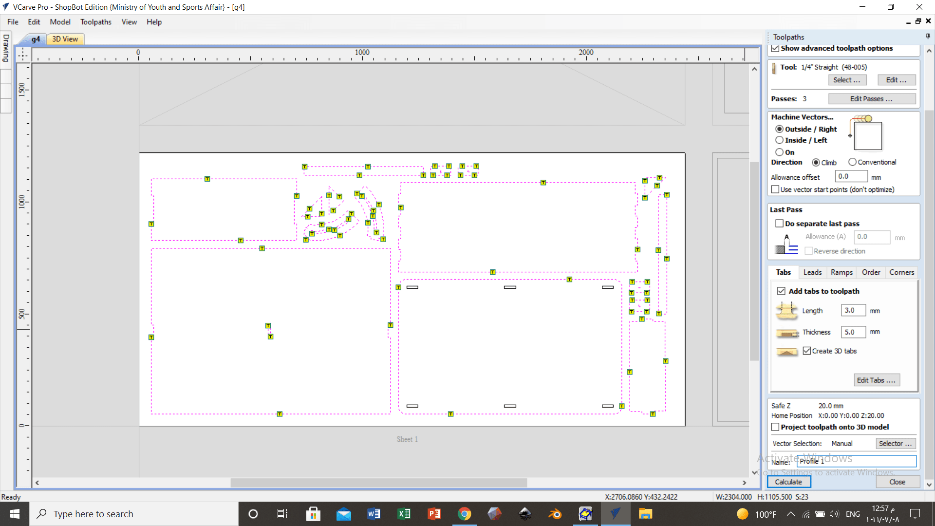
Adding taps is important to follow the machine path.
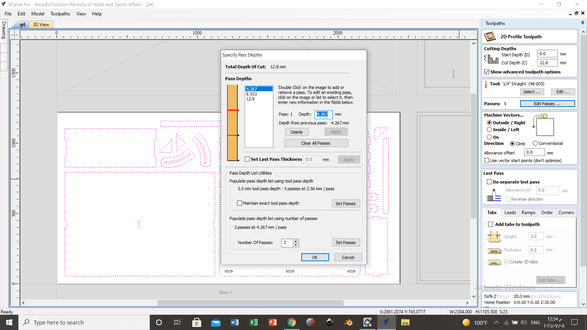
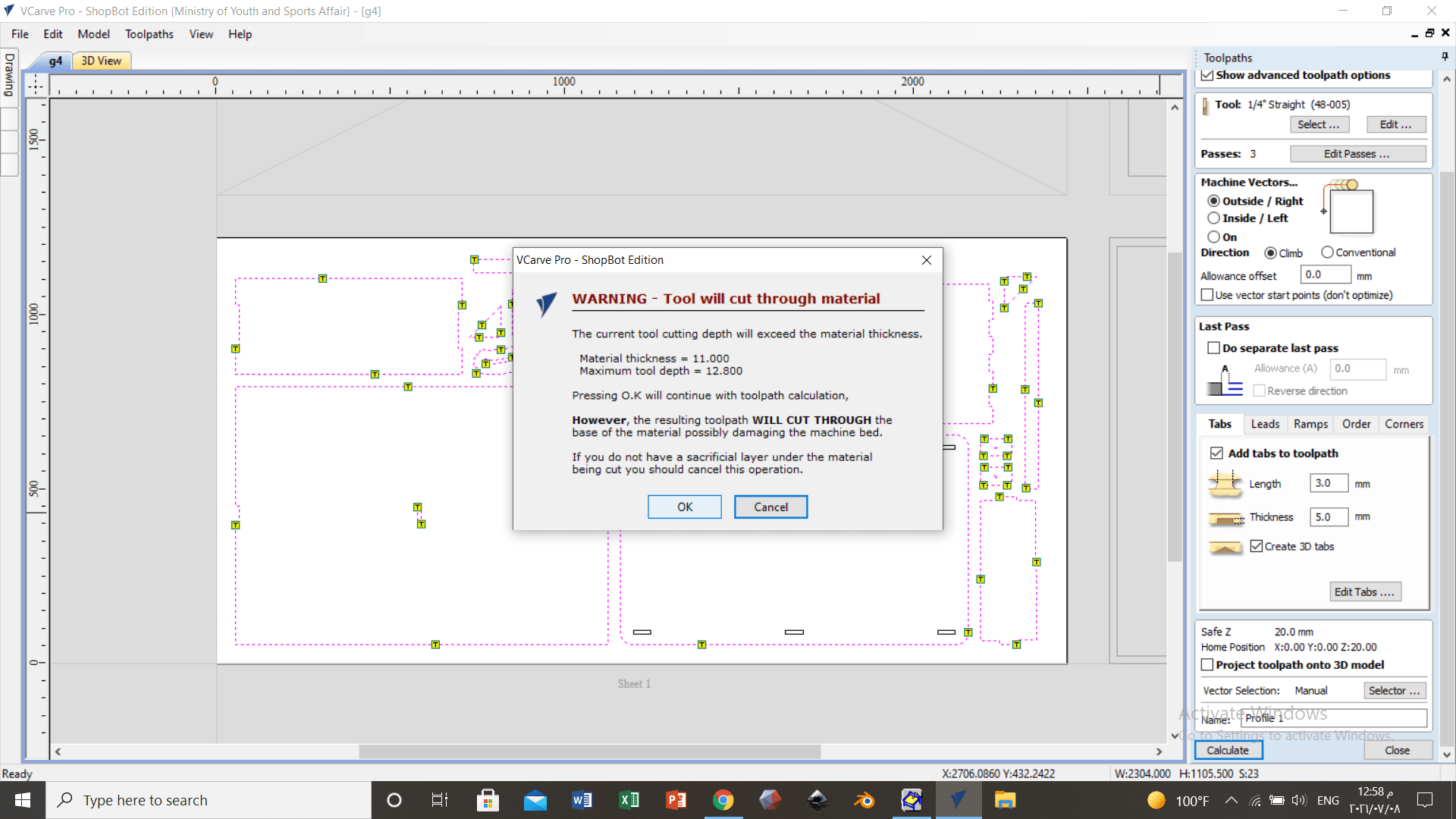
usually the depth specified always more them the thickness of the sheet to make sure it goes through the mainsheet the rest of the depth will go through the sacrifice sheet. This error just notify you about this.
Using toolpath feature to edit the drillpit parameters for the pockets.
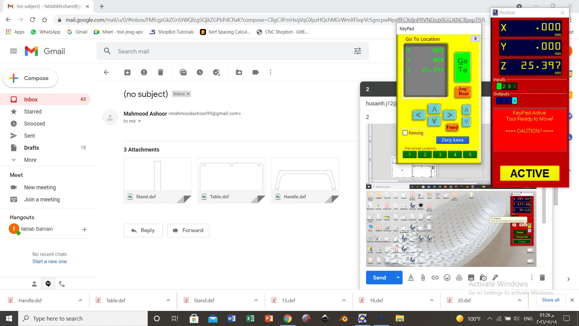
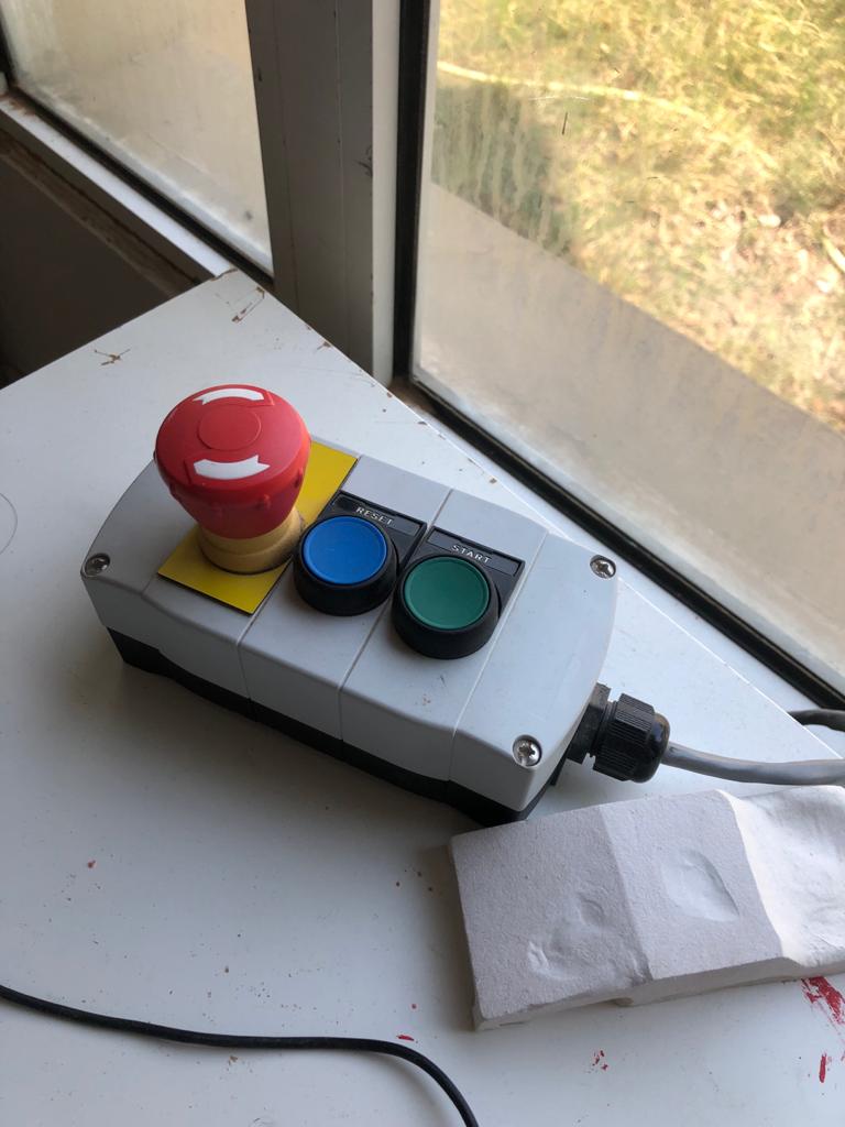
This is the control panel of the CNC machine.

Using a connected measuring tool so that the device can understand the heights.

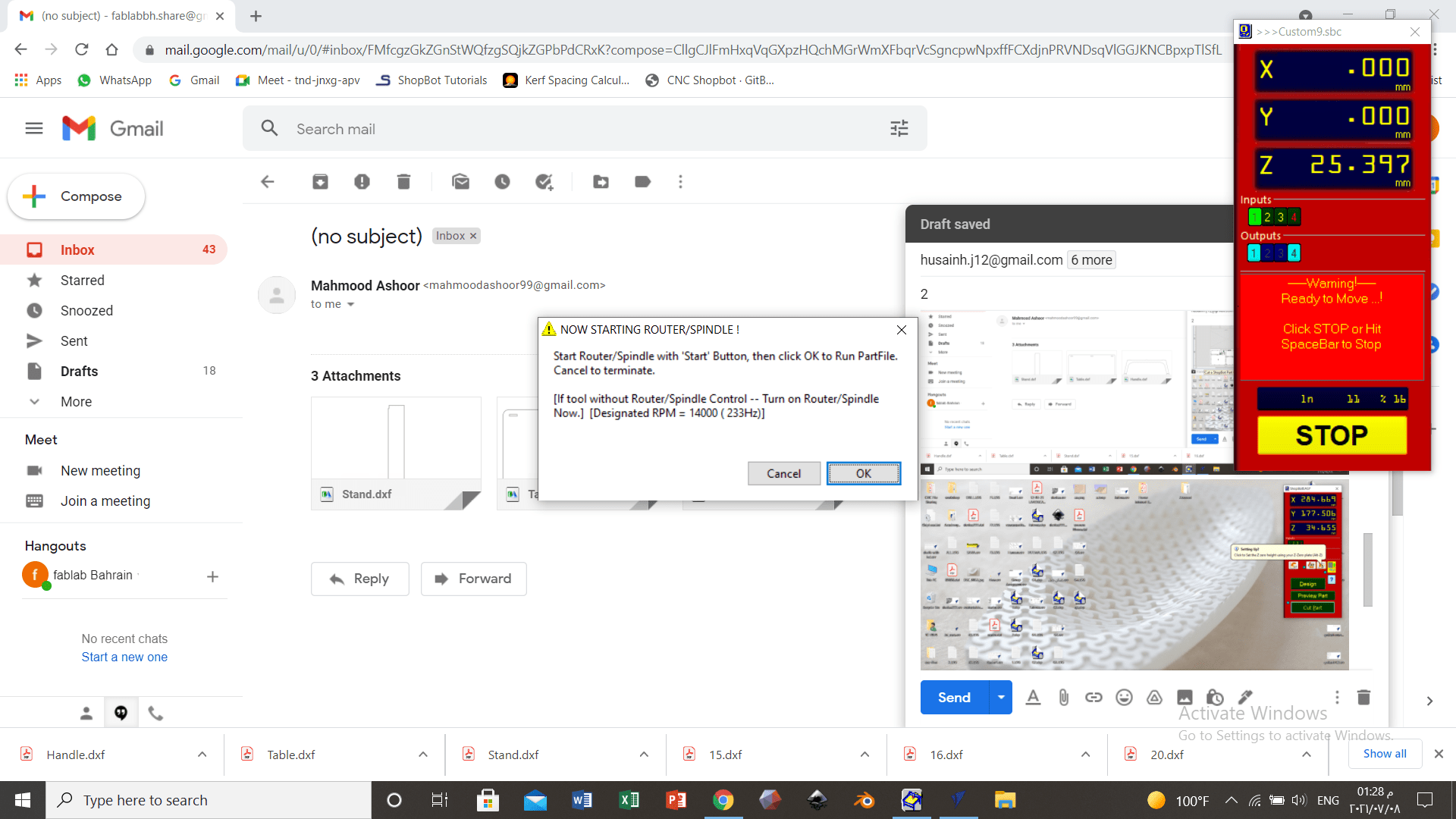
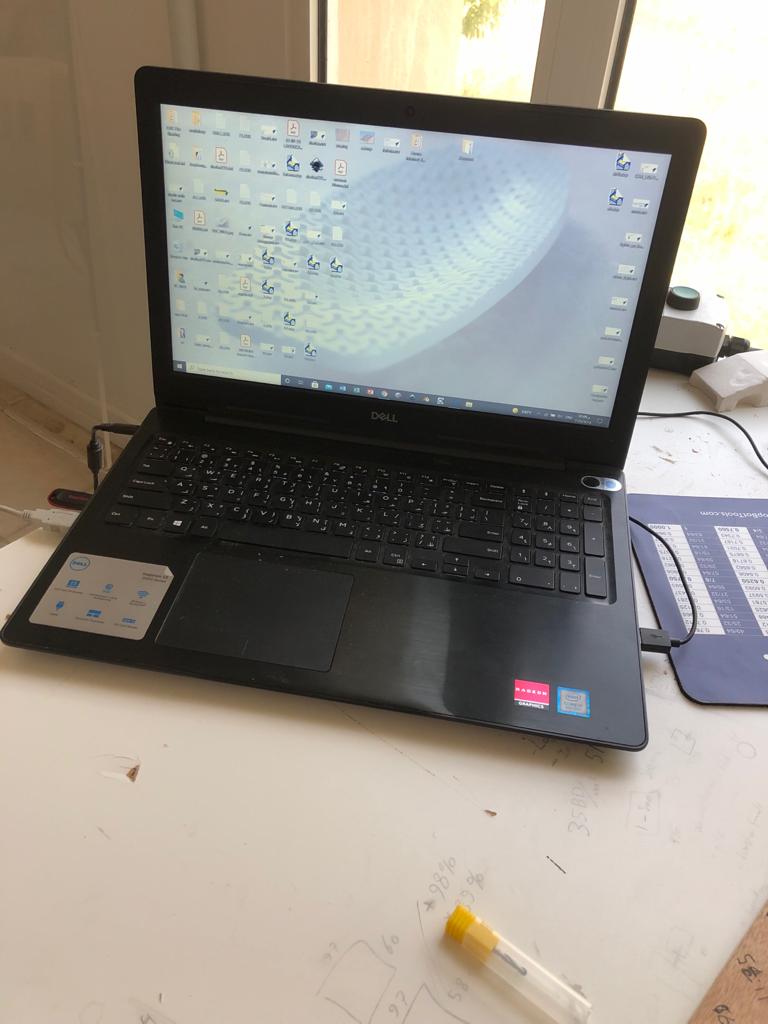
The last notification before the machine starts.
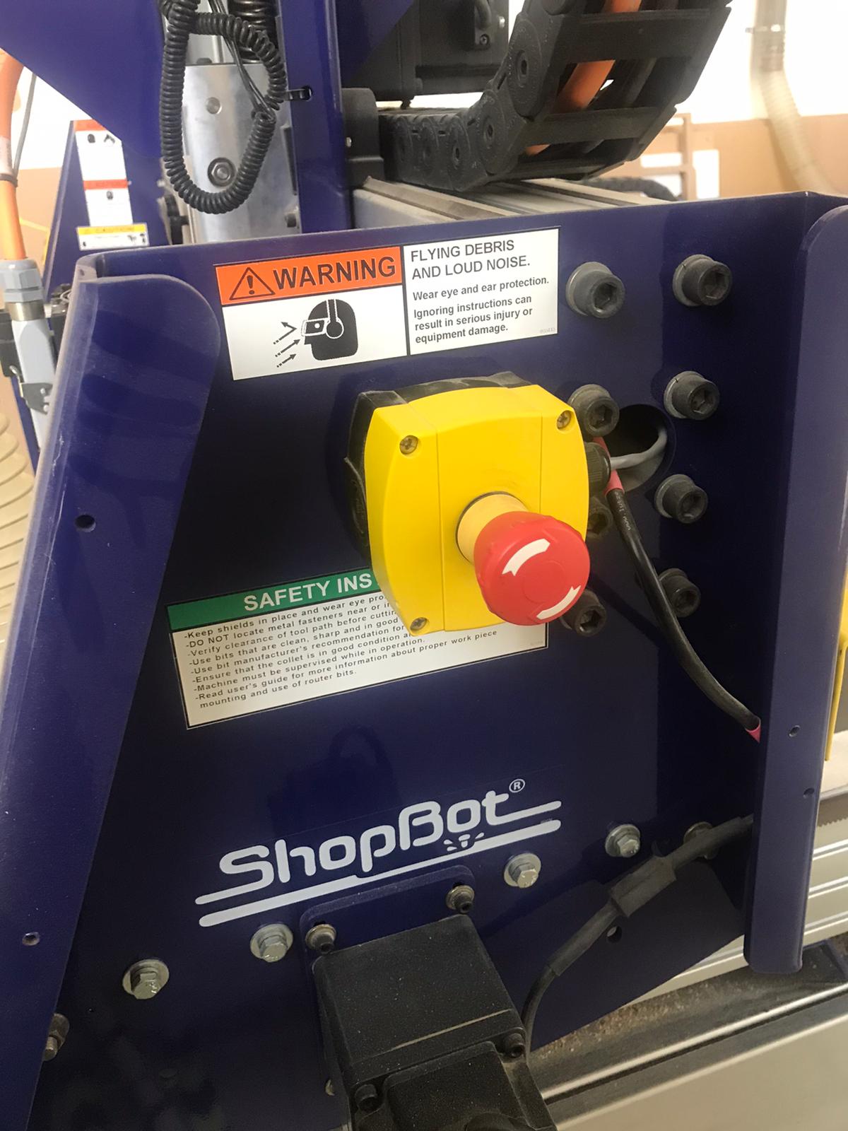
Emergency buttons are necessary to stop the machine if anything happened. Also pressing any button in the laptop will pause the progress of the machine.
The size of the sawdust can tell whether the machine performance + settings are perfect or not.
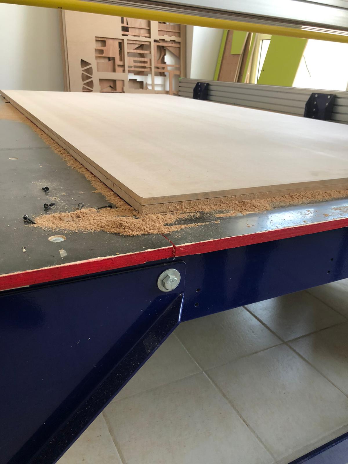
Vacuum machine is important to suck up the sawdust to keep the drillpit path clear.
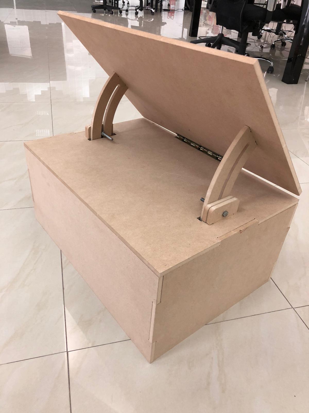
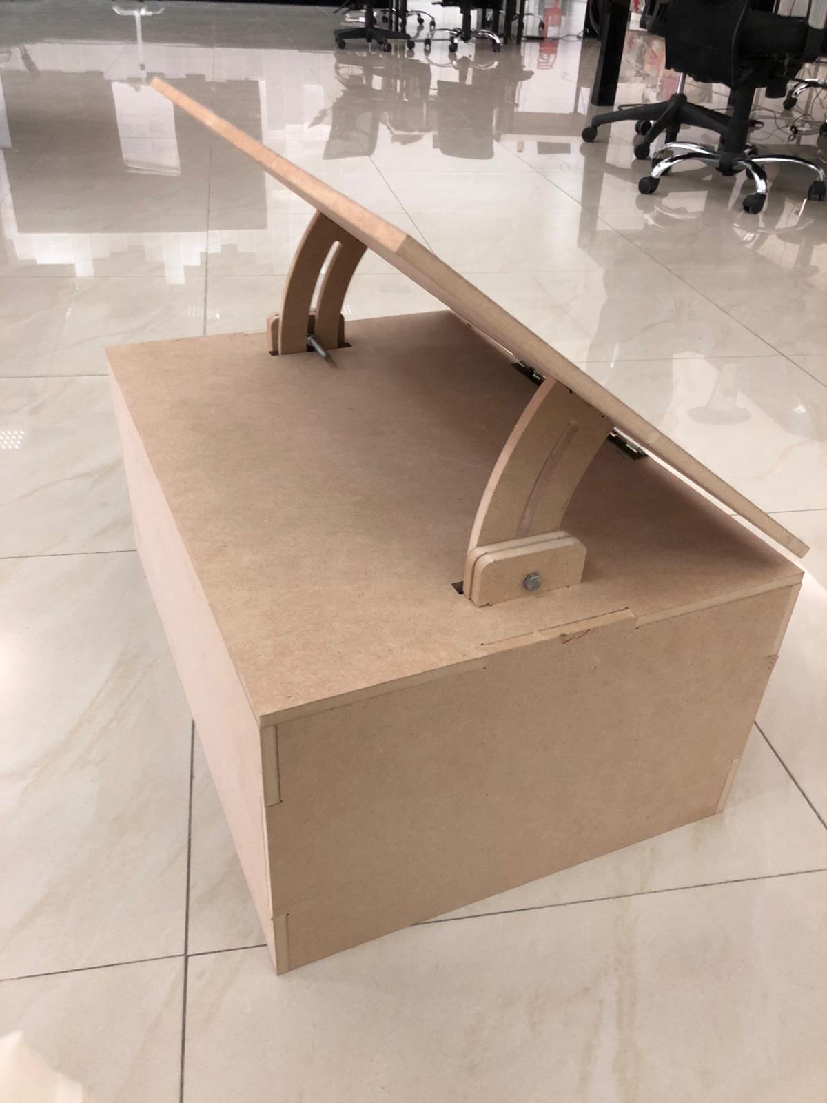
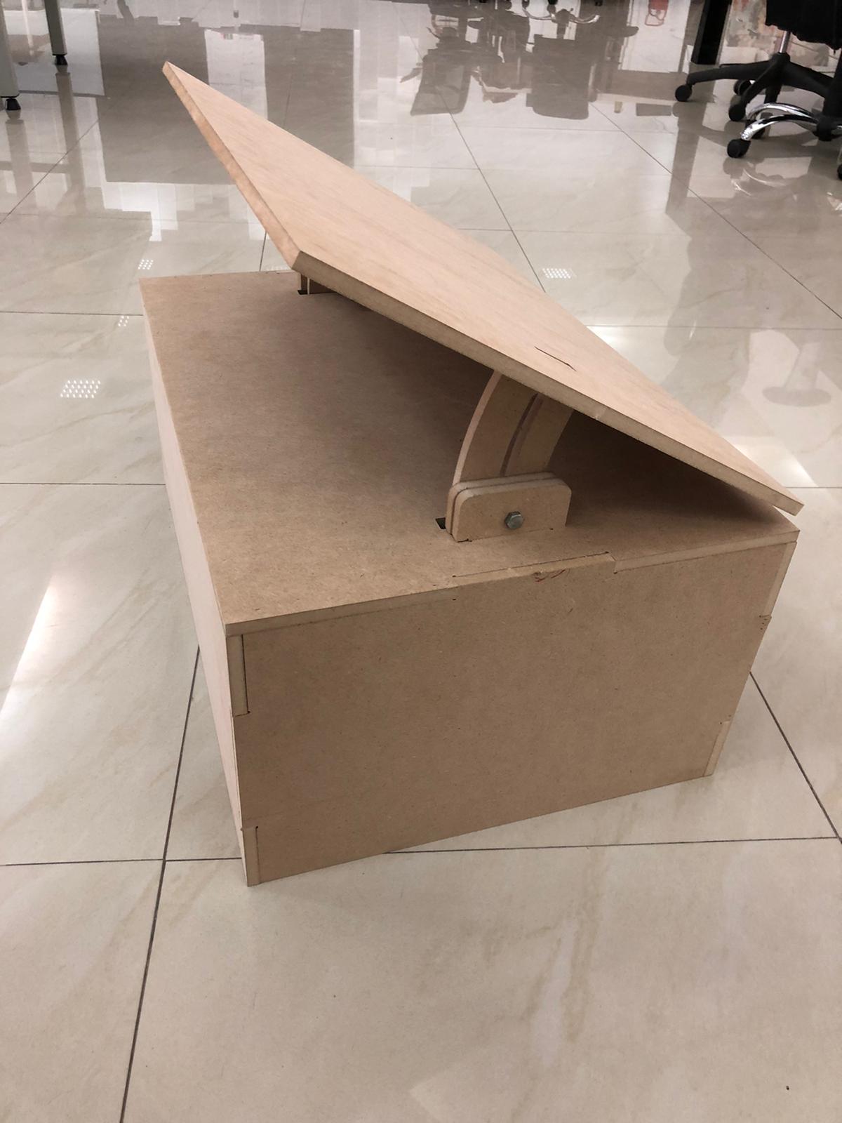
Assembling process
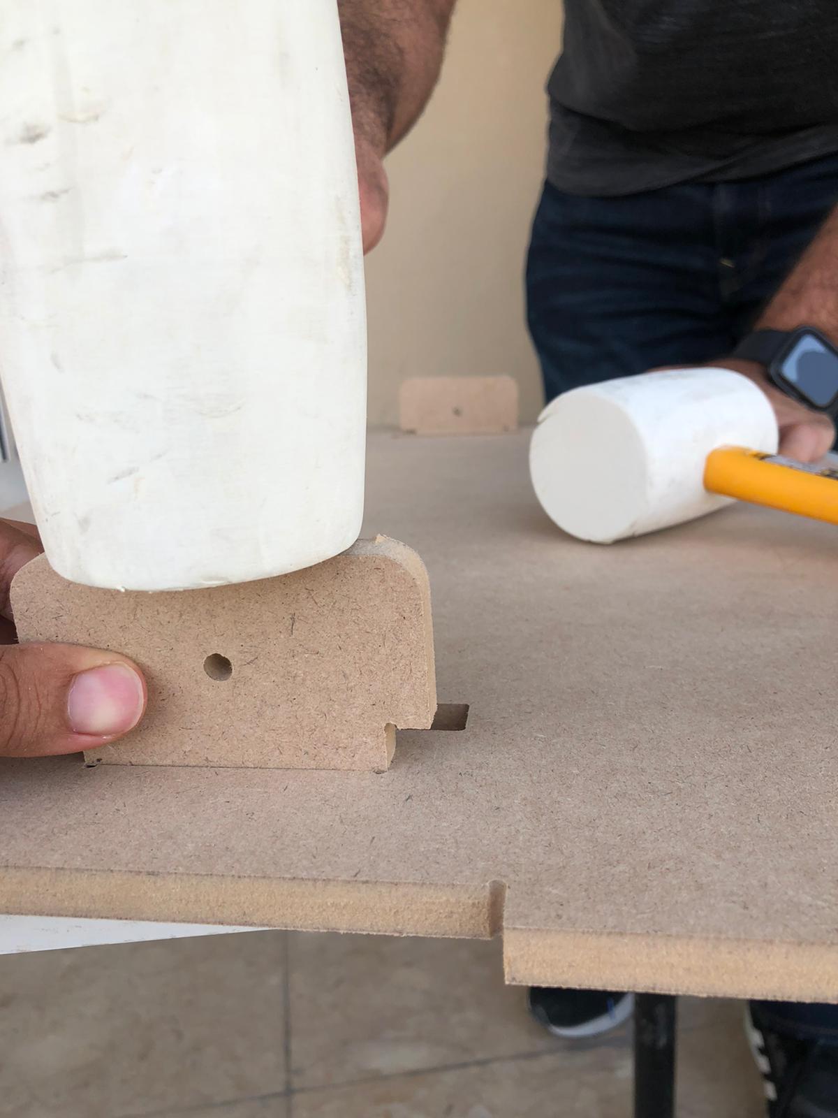
The assemble process with the help of my friend Abdulla
Assembling the level controller and adjuster.
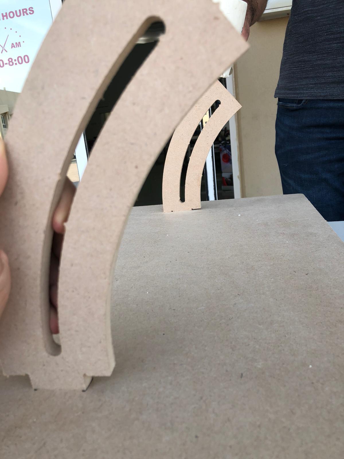
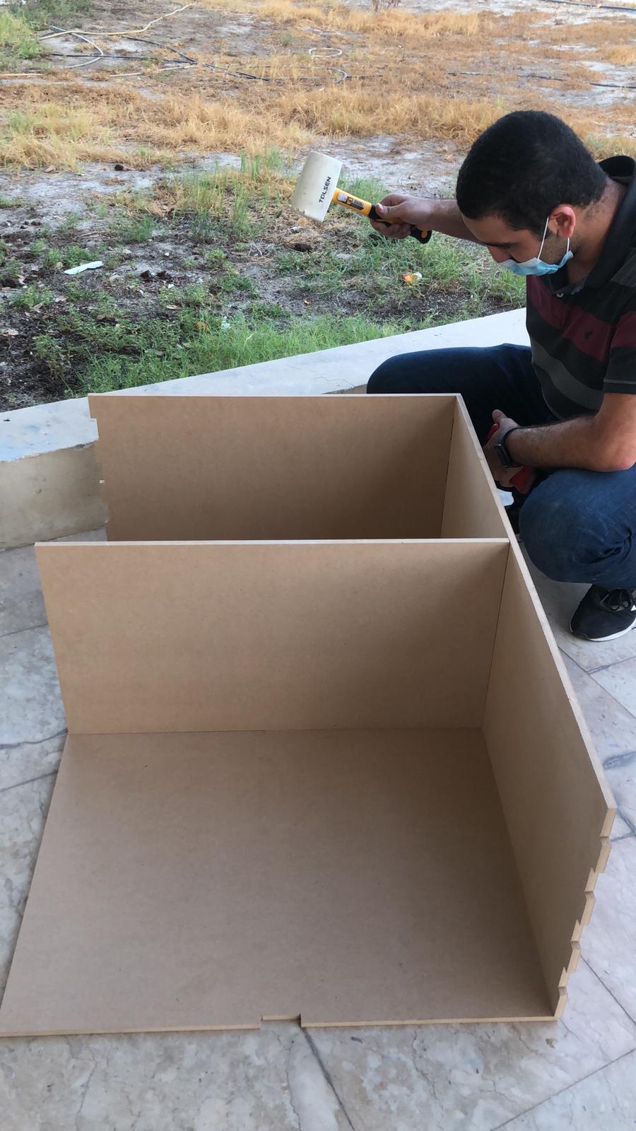
Assembling the base
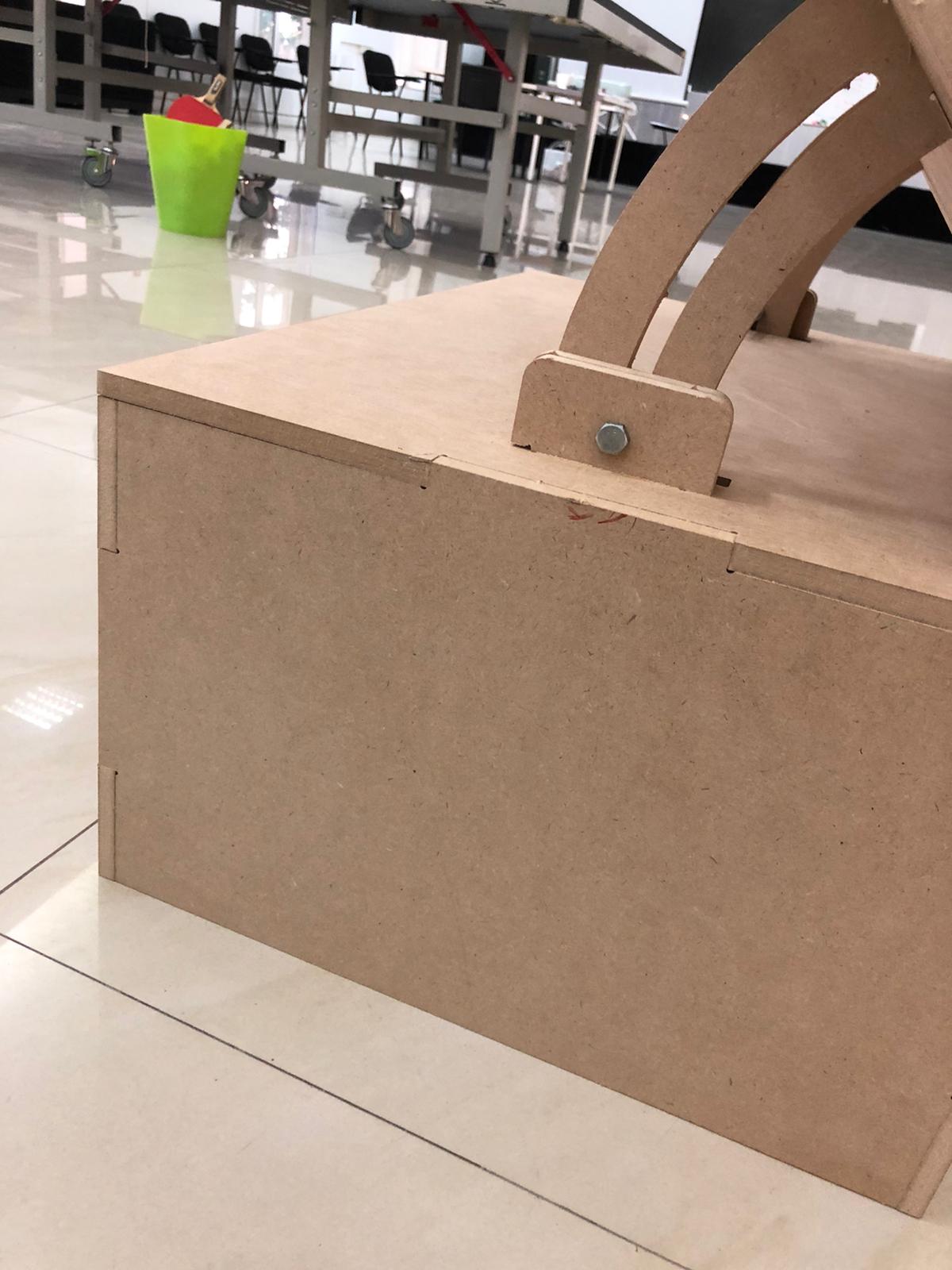
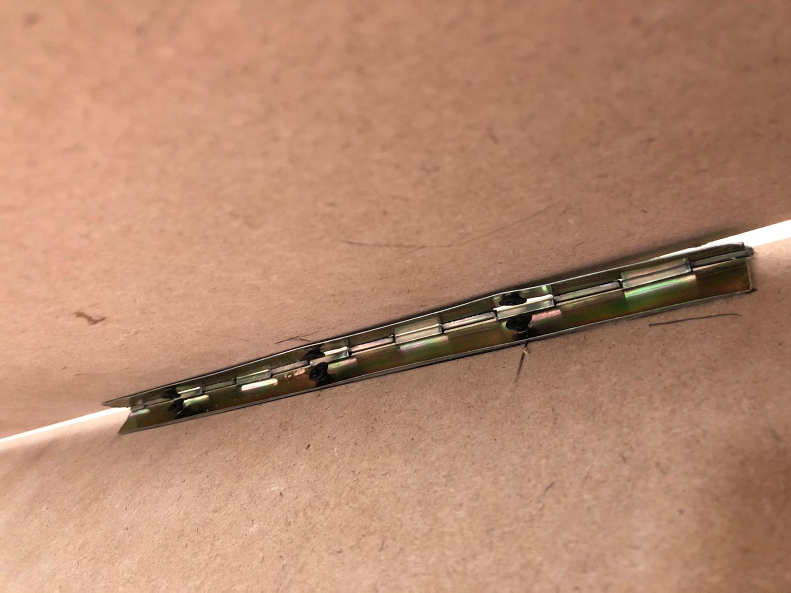
Adding the hench
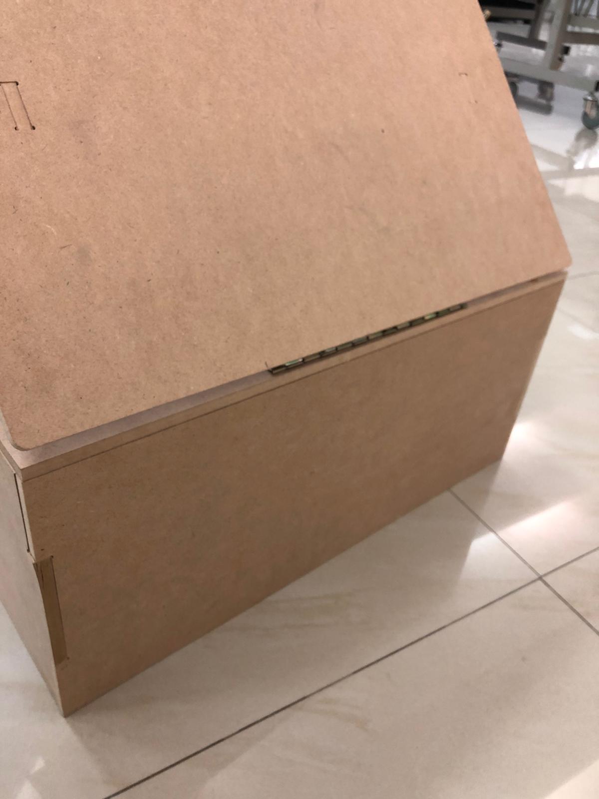
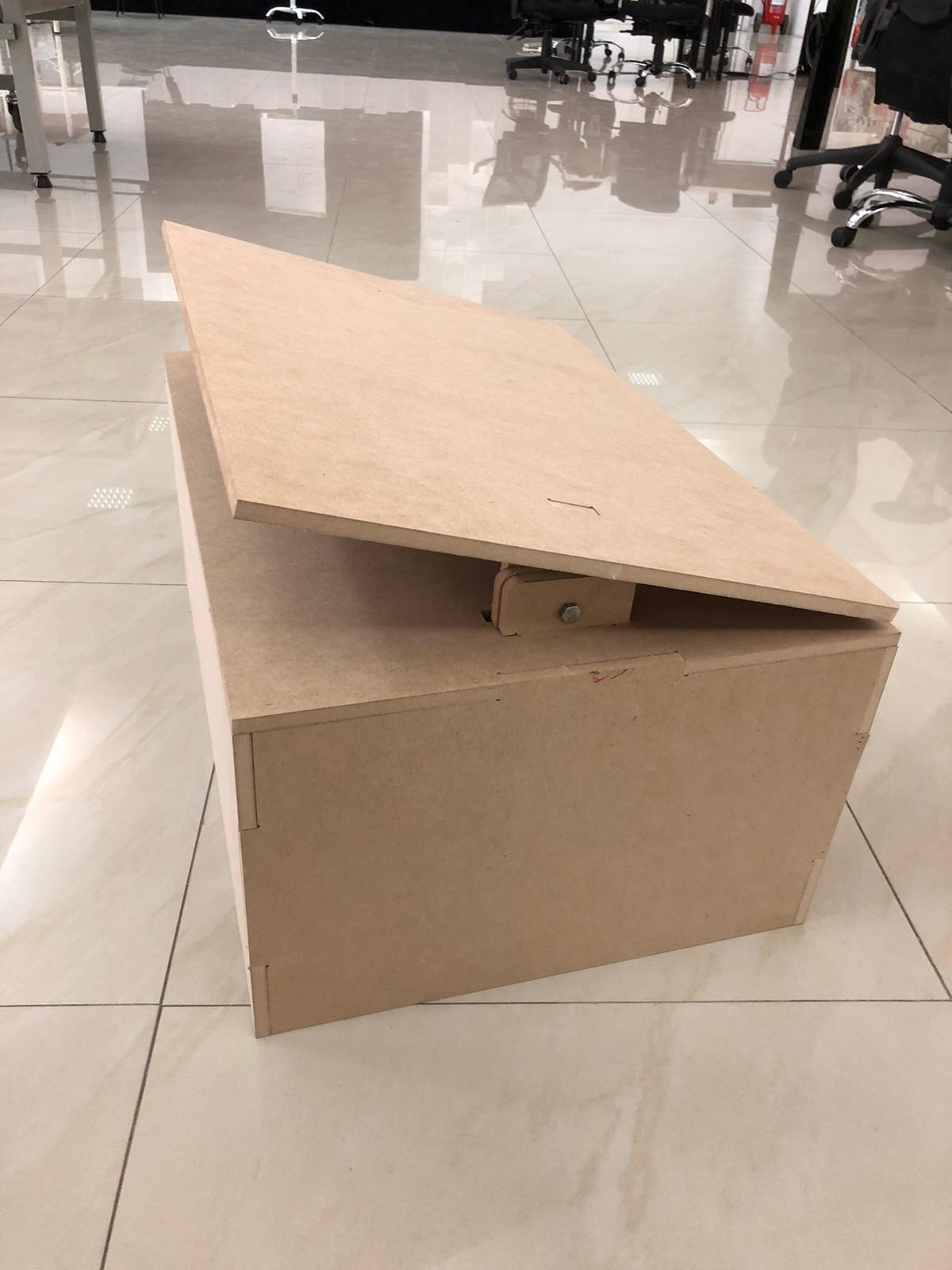
Final Result